
Electric King Condor Trainer
INTERESTED in electric-powered model flight? Before your electrified thoughts get short-circuited, read on. Offered here is perhaps the quickest, simplest, and least expensive way to investigate this intriguing and different method of RC flying.
Electric power has been available for model use for over 15 years, and it is now apparent that it offers some exclusive advantages. In the past, when considering this power source, most modelers compared it to glow engines, and then the advantages of electric flight quickly dimmed. It was tough to give up ample engine power for the restricted performance that electric motors initially offered.
If you've been paying attention, you may have noticed the giant strides that have been made in electric power systems in the last few years. It is now possible to electrically duplicate glow engine power up to about .40 cu. in. size, a range that is more than enough for good sport flying. Lots of modelers are finding enjoyable performance from the much smaller and less expensive .05 motors.
Along with the increase in electric motor power has come a significant reduction in system weight. While electric power may never match glow power on a weight basis, modelers are finding electric systems have more than enough power to make their planes fly — and fly well. The simple solution was to design the model structure to eliminate excess strength (and weight) where it wasn't needed.
To be attractive, a power source must also be affordable. Glow engines have been around long enough to offer us a pretty good power-to-dollar ratio — as yet unmatched by electrics. Paul MacCready has shown us some wonderful things that can be done with electric (even solar) power with heavy financial backing. Fortunately, we are now seeing electric systems for models which don't shock our pocketbooks while filling our needs.
In this line of thinking we have to forget about comparing various power sources and concentrate on our basic requirement for an average-sized model with enough performance for enjoyment. This accounts for the great popularity of the various .05-size electric systems. Their cost falls in the range of a good sport engine for similar-sized models, and .05 performance has proven to be quite satisfactory.
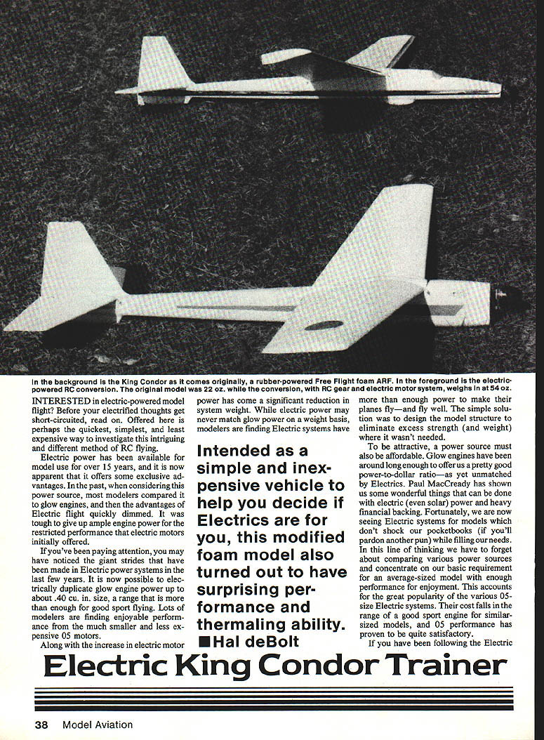
Intended as a simple and inexpensive vehicle to help you decide if electrics are for you, this modified foam model also turned out to have surprising performance and thermaling ability. — Hal deBolt
Overview
If you've asked yourself whether the average modeler can have successful and rewarding flights using accustomed building methods and materials, a stock electric motor power system, and standard RC gear, the answer is yes. This model is proof of that and proof, also, that it can be done without changing your lifestyle. However, you should realize that electric power is a major change from glow engines, and you will have some relearning to do.
It is wise to heed the advice of those who have paved the way for electric flight and use a "trainer"-type model to start with. After you've learned the principles of electric operation and flight, you can put in the bigger effort for your electric masterpiece. This particular electric trainer is not intended to teach the rank beginner how to fly. It is for the more experienced modeler to learn the basics of this new type of power. It fills the design requirements, is readily obtainable, inexpensive, and simple to put together. These things make the initial lessons about electric flying as painless as possible. As an added bonus, it provides some very delightful fun flying.
The electric gurus tell us that an electric trainer should be of the glider variety with enough wing area for a light loading and rather slow flight. This equates to about 600 sq. in. wing area for the .05 motors. With this consideration plus the concepts of minimum cost and time investment, our choices were narrowed to the Styrofoam ARF category of kit models. Without too much effort we came upon two molded foam offerings that filled the bill. Previous experience with both models indicated they offered excellent performance with aerodynamic qualities quite suitable for electric flight.
First of the two candidates was the Lazy Bird by Midwest Products, a two-meter sailplane. The other was the King Condor giant-sized rubber-powered model produced by the Goliath Whirlwind Aircraft Co. Both of these models could be converted easily to accommodate the battery cells and electric motor. We chose the King Condor.
We obtained the necessary electric items:
- Astro Flight #6505 flight system
- Astro Flight #4005 BC charger
- Astro Flight #4018 belt reduction unit
- Astro Flight #4032 microswitch
(similar items available from Leisure Electronics)
We assembled the model with Jet cyanoacrylate (CyA) and covered it with Goldberg's ColorTex.
Construction
A major consideration with the King Condor conversion is that the model was designed to fly very slowly at a weight of 22 oz. The conversion to electric more than doubled the weight (54 oz. for our model), and flying speeds were greatly increased over the original rubber-powered version. Happily, the needed strengthening can be accomplished easily, and it adds longevity to the basic foam structure.
Wing
We began by epoxy-gluing the two-part wing together at the center and then fiberglassing the joint in the normal manner. To add strength to the plain foam wing, we used the "stressed skin" method by covering it with ColorTex. This material has greater tensile strength than the plastic iron-on films, and it is more compatible with foam since low heat is used. For anyone who believes even more strength is desired, a 1/16 x 3/4-in. sheet cap spar can be inset into the wing's bottom surface. We removed the drooped wing tips for easier covering.
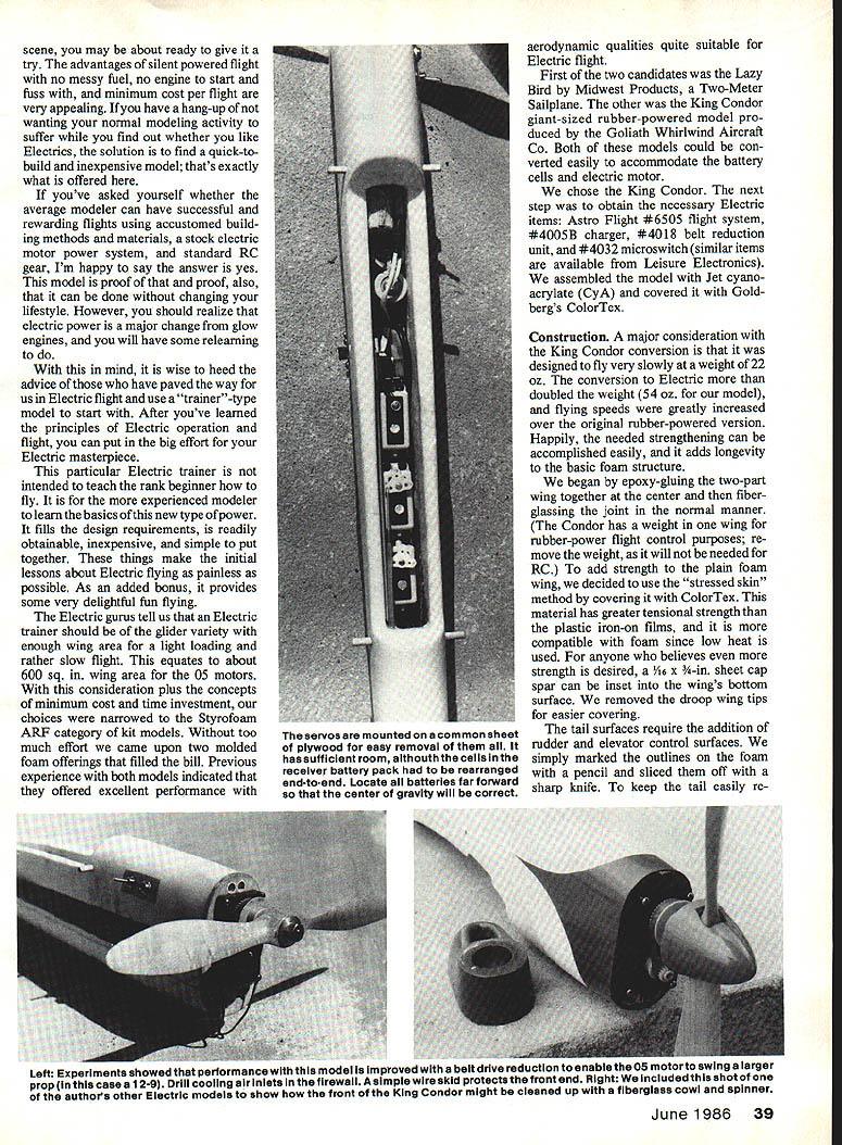
The servos are mounted on a common sheet of plywood for easy removal of them all. It has sufficient room, although the cells in the receiver battery pack had to be rearranged end-to-end. Locate all batteries far forward so that the center of gravity will be correct.
Tail surfaces
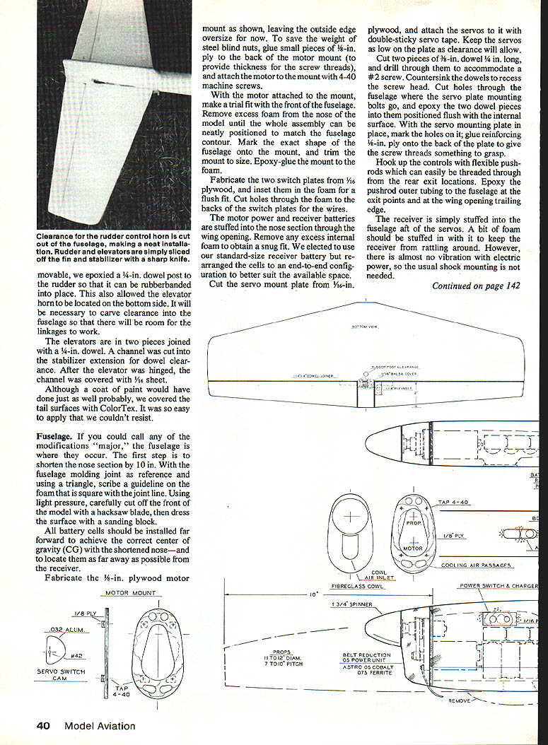
The tail surfaces require the addition of rudder and elevator control surfaces. We marked the outlines on the foam with a pencil and sliced them off with a sharp knife. To keep the tail easily removable, we epoxied a 1/4-in. dowel post to the rudder so that it can be rubber-banded into place. This also allowed the elevator horn to be located on the bottom side. It will be necessary to carve clearance into the fuselage so that there will be room for the linkages to work.
The elevators are in two pieces joined with a 1/4-in. dowel. A channel was cut into the stabilizer extension for dowel clearance. After the elevator was hinged, the channel was covered with 1/16-in. sheet.
Although a coat of paint would have done just as well, we covered the tail surfaces with ColorTex because it was so easy to apply.
Fuselage
If you could call any of the modifications "major," the fuselage is where they occur. The first step is to shorten the nose section by 10 in. With the fuselage molding joint as reference and using a triangle, scribe a guideline on the foam that is square with the joint line. Using light pressure, carefully cut off the front of the model with a hacksaw blade, then dress the surface with a sanding block.
All battery cells should be installed far forward to achieve the correct center of gravity (CG) with the shortened nose — and to locate them as far away as possible from the receiver.
Fabricate the 1/8-in. plywood motor mount, leaving the outside edge oversize for now. To save the weight of steel blind nuts, glue small pieces of 1/8-in. ply to the back of the motor mount (to provide thickness for the screw threads), and attach the motor to the mount with 4-40 machine screws.
With the motor attached to the mount, make a trial fit with the front of the fuselage. Remove excess foam from the nose of the model until the whole assembly can be neatly positioned to match the fuselage contour. Mark the exact shape of the fuselage onto the mount, and trim the mount to size. Epoxy-glue the mount to the foam.
Fabricate the two switch plates from 1/16-in. plywood, and inset them in the foam for a flush fit. Cut holes through the foam to the backs of the switch plates for the wires.
The motor power and receiver batteries are stuffed in the nose section through the wing opening. Remove any excess internal foam to obtain a snug fit. We elected to use our standard-size receiver battery but rearranged the cells to an end-to-end configuration to better suit the available space.
Cut the servo mount plate from 1/16-in. plywood, and attach the servos to it with double-sticky servo tape. Keep the servos as low on the plate as clearance will allow. Cut two pieces of 3/8-in. dowel 1/4 in. long, and drill through them to accommodate a #2 screw. Countersink the dowels to recess the screw head. Cut holes through the fuselage where the servo plate mounting bolts go, and epoxy the two dowel pieces into them positioned flush with the internal surface. With the servo mounting plate in place, mark the holes on it; glue reinforcing 1/8-in. ply onto the back of the plate to give the screw threads something to grasp.
Hook up the controls with flexible pushrods which can easily be threaded through from the rear at exit locations. Epoxy the pushrod outer tubing to the fuselage at the exit points and at the wing opening trailing edge.
The receiver is simply stuffed into the fuselage aft of the servos. A bit of foam should be stuffed in with it to keep the receiver from rattling around. However, there is almost no vibration with electric power, so the usual shock mounting is not needed.
Motor and Switch
The motor unit — an on-off microswitch — is operated with a simple cam. This arrangement offers a large band, eliminating the need for precise or finicky adjustments. The original cam was made from sheet aluminum, but 1/16-in. plywood would work as well. With the cam on the servo, locate the switch so that the cam will contact it at the proper rotation. Mount the switch on a small block and epoxy the block to the inside of the fuselage. Wire the switch in the motor lead so the motor can be shut off positively for landing.
Prop selection for the .05 motor should provide brisk climb and a relaxed cruise; avoid over-propping the motor. From our experience, electric power can be applied in two ways: directly or through a belt drive. While direct drive impressed us with how a little 7-in. prop can pull this large model, performance is considerably better with a belt reduction drive and larger prop. The 11-in. diameter prop is better matched to the model's size and produces a noticeable improvement in performance.
Flying
The balance point (CG) is 4 in. aft of the wing leading edge, but it is not overly critical with this design. If you followed the procedures above, the actual location should come out very close to this.
All trim adjusting is done with the stabilizer. This design uses a lifting tail, so more positive incidence can be added to the stabilizer for trimming purposes without problems.
The No. 1 consideration with electrics is that you don't have the excessive power typical of glow engines. Think before you act, and don't put the model into a situation that would require abnormal power for recovery. If you do this, you will get along fine with the adequate power that is available.
Launching procedure:
- Switch the motor on.
- Run a couple of steps.
- Push the model directly forward in a level attitude.
It should stay at launch altitude for a few feet, then begin a gentle climb. You can let the model stay pointed into the wind and find its best angle of climb with the elevator. The model should reach soaring altitude in a short period.
Otherwise, you can hold level flight and circle the field to your heart's desire. The King Condor is so slow you will be able to enjoy its big trainer-like handling. The only decent maneuvers are stall turns and inside loops, but one should not forget precision flight with figure eights, procedure turns, etc.
Many hours of flying and experimenting with different motor configurations have taught us a couple of things. After experimenting with prop modifications, there was a dramatic increase in thrust to the point where this model is suitable for most electric-powered duration flying — to at least just below competition level. From our experience we would certainly suggest the King Condor as the electric trainer for your indoctrination into this fascinating kind of flight.
Ordering
If the original R.B.I. King Condor kit is not available from your local hobby dealer, it may be ordered from: Goliath Whirlwind Aircraft, Inc. P.O. Box 589 Lathrup Village, MI 48076
Price: $39.95, including shipping and handling. MI residents add sales tax. MasterCard and Visa accepted.
When responding to advertisers, mention that you read about them in Model Aviation.
Transcribed from original scans by AI. Minor OCR errors may remain.

