
ELECTRIC ONE
By careful attention to weight a successful Pattern job can be built using the Astro-25 for get-up-and-go.
Dick Sarpolus
THE IDEA of going to the flying field without spare glow plugs, plug batteries, fuel, fuel pump, muffler, etc., and returning home with a clean plane—no exhaust mess—is certainly an appealing one. No starting problem; just flip a switch and away you go. The manufacturers are to be commended for their efforts to bring on the electric age. After reading about, and seeing the available electric power hardware, we decided to try it—but with a slightly different design approach.
The electric models now on the market could, we believe, be classified as sport, Sunday flier types. Many are essentially powered gliders, even rudder-only types. This is necessitated by the weight of the motor, power supply and limited power available. Astro Flight’s Astro-25 looked the most promising to us as a powerplant for a relatively “hot” model; that is, an aerobatic capable model, not a flat bottom wing “floater.” We wanted to be able to do most of the pattern maneuvers. To do this, our model would have to be configured for aerobatic capability.
How long will your Astro 25 run? What prop should you use? The motor was designed for a 9 x 7 prop, turning at 9,000 rpm on a 15-minute charge—it will run eight minutes. Do not use a 10-in. prop in an attempt to gain more power, advises the manufacturer. This will overheat the motor, burn up armature and brushes, and result in short flight duration.
For a fun model, we had designed the .19 powered Whiplash (published in Nov ’74 AAM) and looked at this as a basis for an electric model. The overall size was increased somewhat to get a reasonably light wing loading. The airfoil was changed to semi-symmetrical; this would give us a better lift capability but still be aerobatic. A full 4-channel installation was planned. Basic aerobatic design—tapered wing, strip ailerons, generous rudder area, etc.—were all used to insure good performance. Nothing revolutionary, just sound basic proportions. Fuselage size was kept to a minimum. This presented the biggest problem due to the size and weight of the necessary battery packs for the Astro-25 motor.
The unusual arrangement of the servo installation behind the wing, accessible through a hatch, enabled us to achieve a normal balance point for the aircraft. The wing was built-up rather than foam-cored, for lightest possible weight. Using vertical spar webs gave the necessary strength. Plywood fuselage doublers are believed necessary because of the battery weight.
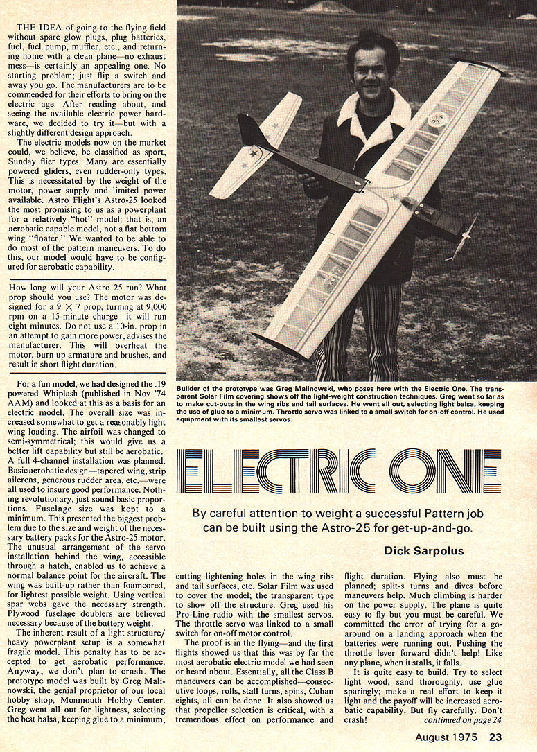
The inherent result of a light structure/heavy powerplant setup is a somewhat fragile model. This penalty has to be accepted to get aerobatic performance. Anyway, we don’t plan to crash. The prototype model was built by Greg Malinowski, genial proprietor of our local hobby shop, Monmouth Hobby Center. Greg went all out for lightness, selecting the best balsa, keeping glue to a minimum, cutting lightening holes in the wing ribs and tail surfaces, etc. Solar Film was used to cover the model; the transparent type to show off the structure. Greg used his Pro-Line radio with the smallest servos. The throttle servo was linked to a small switch for on-off motor control.
The proof is in the flying—and the first flights showed that this was by far the most aerobatic electric model we had seen or heard about. Essentially, all the Class B maneuvers can be accomplished—consecutive loops, rolls, stall turns, spins, Cuban eights, all can be done. It also showed us that propeller selection is critical, with a tremendous effect on performance and flight duration. Flying also must be planned; split-S turns and dives before maneuvers help. Much climbing is harder on the power supply. The plane is quite easy to fly but you must be careful. We committed the error of trying for a go-around on a landing approach when the batteries were running out. Pushing the throttle lever forward didn’t help! Like any plane, when it stalls, it falls.
It is quite easy to build. Try to select light wood, sand thoroughly, use glue sparingly; make a real effort to keep it light and the payoff will be increased aerobatic capability. But fly carefully. Don’t crash!
Electric One
Some notes on the construction. We would suggest cutting out all parts ahead of time; basically make your own kit. This will save time overall. We cut the ribs out individually; never did like the stack-and-sand method. Leaving the "building feet" on the ribs as shown makes the building alignment easy. The lower spar can be pinned to the work board, ribs added, top spar, trailing edge, leading edge, spar webs, leading and trailing edge top planking added. With this much building done before removing the wing from the board, it is not likely to warp before the bottom planking is added. No dihedral brace is necessary; fiberglass cloth/epoxy is more than adequate. Plywood tip plates are quick and easy; may help aerodynamically and will protect from scrapes on bad landings.
Tail surfaces are simply sheet balsa; use lightening holes as you see fit.
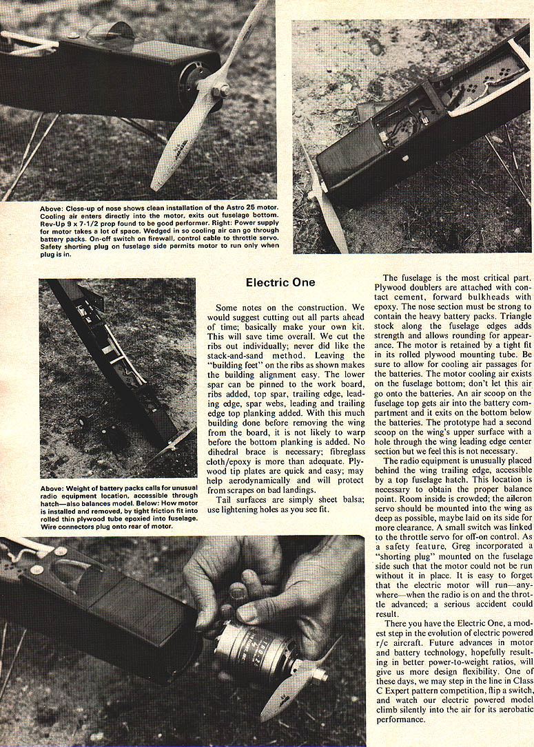
The fuselage is the most critical part. Plywood doublers are attached with contact cement, forward bulkheads with epoxy. The nose section must be strong to contain the heavy battery packs. Triangle stock along the fuselage edges adds strength and allows rounding for appearance. The motor is retained by a tight fit in its rolled plywood mounting tube. Be sure to allow for cooling air passages for the batteries. The motor cooling air exits on the fuselage bottom; don't let this air go onto the batteries. An air scoop on the fuselage top gets air into the battery compartment and it exits on the bottom below the batteries. The prototype had a second scoop on the wing's upper surface with a hole through the wing leading edge center section but we feel this is not necessary.
The radio equipment is unusually placed behind the wing trailing edge, accessible by a top fuselage hatch. This location is necessary to obtain the proper balance point. Room inside is crowded; the aileron servo should be mounted into the wing as deep as possible, maybe laid on its side for more clearance. A small switch was linked to the throttle servo for off-on control. As a safety feature, Greg incorporated a shorting plug mounted on the fuselage side such that the motor could not be run without it in place. It is easy to forget that the electric motor will run—anywhere—when the radio is on and the throttle advanced; a serious accident could result.
There you have the Electric One, a modest step in the evolution of electric powered r/c aircraft. Future advances in motor and battery technology, hopefully resulting in better power-to-weight ratios, will give us more design flexibility. One of these days we may step in the line in Class C Expert pattern competition, flip a switch and watch our electric powered model climb silently into the air for its aerobatic performance.
Transcribed from original scans by AI. Minor OCR errors may remain.

