
ELECTRIC SATELLITE 450
Don Hughes
There is no doubt about it: electric power is making serious inroads in the model airplane hobby. Judging from the number of ads for electric products, a relatively large segment of the modeling fraternity is sold on the idea. Clean and quiet electric power is a natural for sailplanes (silent flight, no launching devices). RC sport fliers appreciate freedom from engine-induced headaches such as vibration, fuel-soaked structures, and noise complaints.
And then there is Electric Free Flight. I often wonder if there is any future for Free Flight as a whole, much less an obscure and seemingly impossible thing like Electric Free Flight. Electric power is at odds with everything Free Flighters hold as absolutes: weight is the enemy, and power is the name of the game. Since most Free Flighters are competitors, the search is for faster engines, better rubber, exotic materials, and incremental design improvement.
Why would anyone be interested in a concept where the battery and motor weigh more than an entire gas model? Furthermore, the performance is touted to be about as exciting as watching paint dry. The guy who put the first electric motor into a model certainly didn't do it as a challenge to F1C fliers! I've never fully understood how enough interest was generated to get Electric FF accepted as an official AMA competition event. I can only relate my personal experience.
For several years before 1984 I was an avid Wakefield flier. The only thing I disliked about Wakefield was what I call the time-preparing vs. time-flying ratio. The constant making and testing of rubber motors really detracted from my enjoyment of flying. Astro Flight ads caught my attention, and I rigged an old Wakefield 035 ferrite motor driven by six Sanyo N-250 Ni-Cds. It flew well enough to take second at the 1984 Reno Nats. I was hooked.
As they say, "That was then, and this is now." What can you expect from FF electrics today? The best models will climb about like a nostalgia gas model; the limiting factor is available power and weight. The surprise is how well these models glide. The typical 9–10 oz-per-sq.-ft. wing loading doesn't seem to materially detract from glide performance. In fact, the extra weight makes them good windy-weather fliers. With the extra motor run allowed Electrics often out-climb gassies and thermal just like any other model.
What can we expect in the future? I wish I knew. One thing is certain: better motors and batteries will become available if the RC car phenomenon is any indicator. Looking back six years, electrics have improved from being a curiosity to real performers.
Why aren't more free flighters into electrics? In my opinion, gas fliers just aren't interested in something that "flies almost as good as a gas model." Quiet flight isn't much of a factor in Free Flight anymore. Perhaps the entire Free Flight concept is outdated and will one day be confined to tiny reservations allowing silent or highly muffled limited-performance models. Small electrics will fit right in. Until that sad day, progress in FF electrics will continue to be pushed by people who enjoy doing something different and challenging. If you are that kind of person—or someone doing electrics now but looking for something better—the model presented here will get you on the right track.
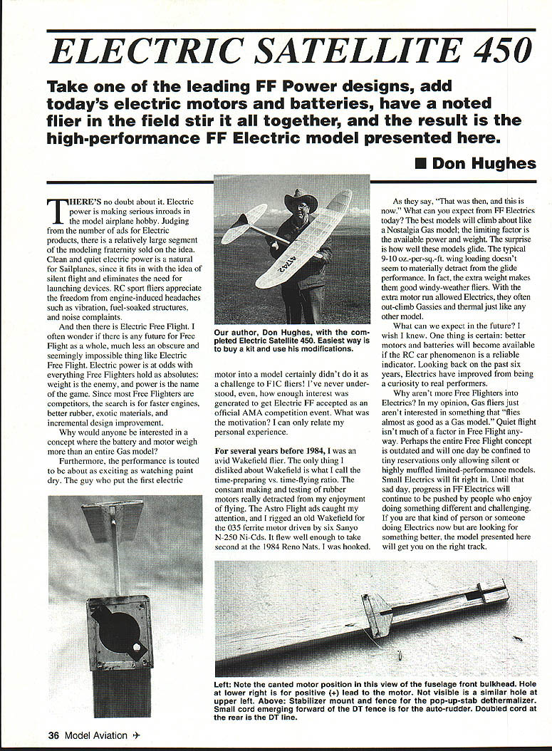
The Satellite, designed by Bill "Bob" Hunter about 16 years ago, has been one of the most successful and popular competition Free Flight power models ever. I've been using the 450 version converted to electric motor power for the past five years and it continues to be a favorite. Sure, advanced designs have more performance potential, but the Satellite 450 has a lot going for it.
First, the Satellite 450 is available in kit form from Jack's Models, 7178 Aumsville Hwy SE, Salem, OR 97301. It's easy to build, flight-adjust, and consistent. Best of all, it's tough and doesn't require a lot of special reinforcement for electric use. Electrics can stand anything: DT landings and extra weight really stress the fuselage, especially the wing. High-aspect-ratio designs require high-tech techniques and exotic materials to prevent fractures on impact; the Satellite wing can be built essentially stock and covered with plastic film. The fuselage requires some redesigning to accommodate electric motor hardware, but the basic model and layout remain unchanged.
If you are an experienced gas flier, I suggest you build the Satellite to get the feel of electrics. Then adapt the electric concept to more sophisticated designs. If you are new to FF power, this is an ideal starter model that performs way above most people's expectations. Build the six-cell, Class A version first to gain experience, then build another for seven-cell, Class B and be pleasantly surprised.
Until recently there hasn't been a really good motor for Class A (six-cell) competition. I could make the Satellite 450 perform well with a variety of motors, but it took at least ten cells to do a proper job. This many cells creates the illusion of complexity and discourages entry into FF electrics. In addition, most reasonably priced battery chargers only handle six to seven cells.
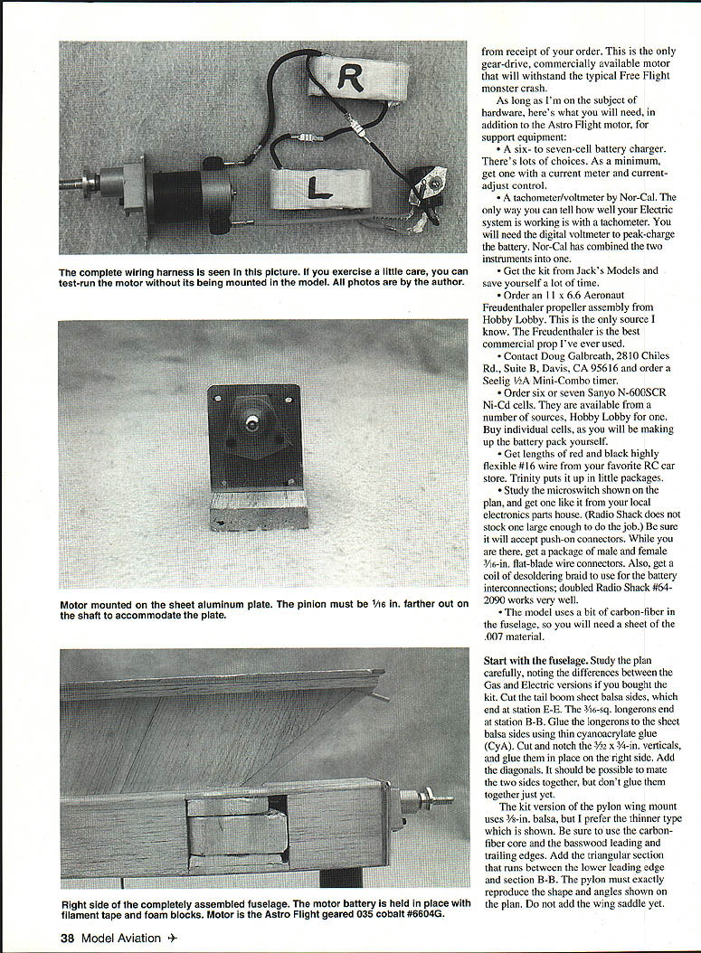
Astro Flight now makes a special Free Flight version of its geared 035 cobalt motor that really hums on six or seven cells, and I don't recommend anything else. Bob Boucher has given it catalog number 6604G, and the price is $119.95; delivery should be in a couple of days from receipt of your order. This is the only gear-drive, commercially available motor that will withstand the typical Free Flight monster crash.
Recommended hardware and supplies
- Astro Flight geared 035 cobalt Free Flight motor (catalog 6604G)
- Six or seven Sanyo N-600SCR Ni-Cd cells (buy individual cells; you will assemble the pack)
- An 11 x 6.6 Aeronaut Freudenthaler propeller assembly (order from Hobby Lobby)
- Seelig 1/2A Mini-Combo timer (contact Doug Galbreath, 2810 Chiles Rd., Suite B, Davis, CA 95616)
- A six- to seven-cell battery charger (minimum: current meter and adjustable current control)
- Nor-Cal tachometer/voltmeter (combined unit recommended)
- Red and black highly flexible #16 wire (RC car stores carry it)
- Microswitch (study the plan; Radio Shack does not stock one large enough—use an electronics parts house). Be sure it accepts push-on connectors.
- Male and female 3/16-in. flat-blade wire connectors
- Desoldering braid for battery interconnections (doubled Radio Shack #64-2090 works well)
- Sheet of .007 carbon-fiber for fuselage reinforcement
- 1/16-in. plywood, balsa, basswood, and other standard kit materials
- Clear Micafilm (or Solarfilm) for covering
Fuselage construction
- Study the plan carefully, noting the differences between the gas and electric versions if you bought the kit.
- Cut the tail boom sheet balsa sides, which end at station E–E. The 3/16-sq. longerons end at station B–B. Glue the longerons to the sheet balsa sides using thin cyanoacrylate glue (CyA).
- Cut and notch the 3/32 x 3/4-in. verticals and glue them in place on the right side. Add the diagonals. It should be possible to make the two sides together, but don't glue them together yet.
- The kit pylon wing mount uses 3/8-in. balsa, but I prefer the thinner type shown on the plan. Be sure to use the carbon-fiber core and the basswood leading and trailing edges. Add the triangular section that runs between the lower leading edge and section B–B. The pylon must exactly reproduce the shape and angles shown on the plan. Do not add the wing saddle yet.
- Glue the two fuselage halves around the tail boom assembly and make sure the pylon wing mount is aligned correctly. Reinforce the motor-face bulkhead area with an extra 1/32-in. plywood doubler on each side and add the motor-mounting plate from the plan.
- Mark the location of the battery pack and the on-off switch so you can check balance. Install the microswitch and wiring harness but don't solder the motor wires to the switch until after final bench tests.
- Trim the pilot's hatch to fit snugly over the battery pack and hold it in place with a small piece of hook-and-loop fastener or a rubber band.
- Mark a horizontal line on both sides of the pylon to show the path of the upper longerons. Glue 3/32 x 3/16-in. filler strips to the inside of each longeron from the pylon trailing edge forward to the end of the longerons.
- Assemble the fuselage sides and try the fit of the pylon. Disassemble, then position the pylon on the right fuselage side with the top longeron aligned along the pylon line. Glue the top longeron on only to the pylon, pin the fuselage side to the plan, bend the longerons to align everything, then glue the bottom longeron to the pylon. Add the left fuselage side and the 3/16 x 9/16 filler between the longerons forward of the pylon.
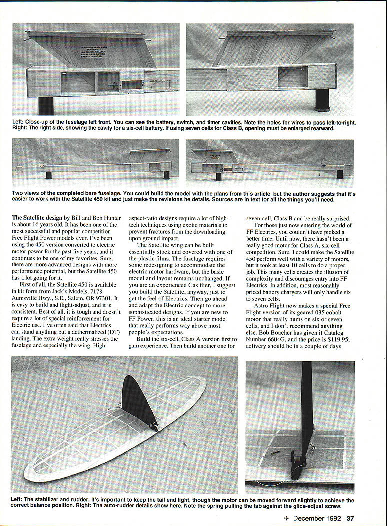
- Cut bulkheads, top cap, filler strips, and 1/16 plywood bottom. Glue the top cap in place on top of the top longerons. Glue sections B–B, D–D, and E–E bulkheads in place. Add the top and bottom 3/16 filler strips and the 1/16 plywood bottom. Add the 1/16 nose and 1/16 side sheeting, then the wing saddle. Complete the rest of the structure except for the tail boom bottom sheeting.
- Complete the fuselage by adding the 1/16 balsa bottom sheeting. Wrap the nose at the plywood bulkhead with fiberglass or 3/4-in. nylon reinforcing ribbon. Finish the fuselage as you like; a few coats of dope will show workmanship. Note there is no landing skid—spreading the impact over the fuselage length and the plywood bottom prevents serious damage.
Control lines, DT and autorudder
- The control lines for the DT and autorudder run internally just under the bottom sheeting as shown in section F–F.
- Use .015 piano wire for the main section of the DT line forward of the tension spring. Bend a small loop in the wire end to attach it to the timer release arm.
- Use very strong Dacron line for the portion between the tension spring and the stab hook, and for the autorudder line. You will need a light spring in the autorudder line and a means of connecting it to the rudder tab.
- My system: a short length of Dacron with a small screw tied to one end is fastened to the rudder tab. This screw threads part-way into a small spring at the end of the autorudder line emerging from the top of the fuselage ahead of the stab fence, providing both a connection and line tension.
Autorudder auto-start device:
- A section of .015 wire is guided through a piece of 1/16 tubing to block the timer fan. A piece of tubing is threaded over the wire and mashed to provide a thumb pad. The end of the wire is connected to a light spring. To arm the release, hold your thumb on the mashed tubing and connect the spring to the hook on the fuselage side. Launch and release your thumb; the spring withdraws the wire from the fan and the timer starts. I prefer this to manually starting the timer.
Motor mounting, break-in and timing
- When ordering the Astro Flight motor, tell them you intend to use a 1/16-in. aluminum plate behind the motor front face and the gear drive assembly for the motor mount. This means the small pinion must be located 1/16 in. further out on the motor shaft. The pinion is pressed onto the motor shaft; it's easier to do this before the motor is shipped.
- Reinforce the motor-face bulkhead with plywood doublers and add the motor-mounting plate shown on the plan. Cut the plate oversize, drill motor shaft and gear-drive mounting holes, and attach the plate to the motor. The motor brush axis will be canted depending on the individual motor timing. Slip the motor into the nose cavity, pressing the plate against the bulkhead. Use the nose bulkhead as a pattern to finish the plate. Fasten the plate with 2-56 screws and T-nuts.
- The foam cowl keeps dirt out of the gears and is fastened with filament tape.
Break-in procedure:
- Inspect motor brushes to see if they are fully arced. Partially arced brushes will not safely handle the current and will require further break-in.
- Use a battery charger as a voltage source, set around 4 V. Be sure the motor rotates clockwise (opposite prop rotation).
- Loosen the motor through-bolts and rotate the brush end-bell while the motor runs. Observe the current meter and position the end-bell for minimum current. Tighten motor screws.
- Run the motor until the brushes are fully arced. The motor will get hot—provide cooling (I use the freezer with leads outside). It may take several hours.
Timing:
- Optimum timing is the brush position relative to the magnets that gives the highest rpm at the lowest current. Time the motor with the prop and battery pack you intend to fly with. Factory timing marks may not be best for your voltage and load.
- Wrap the front portion of the motor with masking tape to bind the front end-bell to the center section and remove the motor through-bolts to allow free rotation of the end-bell.
- Install the prop and wiring harness. With an assistant operating the microswitch, rotate the end-bell and note the position giving maximum rpm (and least advance). Repeat tests to validate results. Mark the end-bell and center section so you can repeat the setting.
- If threaded holes in the end-bell do not align with the gap between magnets when reinstalling through-bolts, drill and tap new 2-56 holes in the end-bell.
Propeller thrust washer tip:
- The propeller will fold forward unless you make a small modification to prevent it. Make a 1 x 1/16-in. aluminum strip, drill the center to fit over the prop shaft, place it on the shaft under the prop hub, and bend the strip tips rearward so the prop is held in proper position. The strip will act as a thrust washer and keep the prop hub from backing off the shaft.
Battery pack assembly and charging
- Make up two packs of three cells each using doubled desoldering braid soldered directly to the individual cells. Although Ni-Cd manufacturers caution against soldering to cells, soldering gives much less contact resistance than small welded tabs. Less resistance means more output voltage and higher rpm. Solder quickly to minimize heating and use masking tape to bind cells together. Keep leads as short as possible.
- Initial charge: even though the cells are quick-charge variety, the initial charge should be slower (about 1 amp). Monitor charge voltage with the digital voltmeter: voltage slowly increases as the battery takes charge; when the voltage peaks and then drops about 0.02 V, the charge is complete. Subsequent charges can be done at four amps. Ni-Cds must be charged and discharged several times before reaching full potential.
- Use the digital voltmeter to peak-charge the battery and the tachometer to verify system performance.
Wiring
- Wiring is straightforward. Study the wiring diagram on the plan and the photos. Diodes/connections allow disassembly of components without unsoldering.
- Keep connections short and use good connectors. Use silicone rubber to insulate microswitch connections from possible shorting by the springs.
- I have not included a fuse or on-off switch in my wiring; if you prefer, add one. Each connection can represent potential voltage loss and wiring complication—decide based on your comfort level.
Wing, stabilizer and covering
- Wing and stab have conventional construction. Keep the stab/rudder very light—my three measure within 4 grams of each other and the target weight of 1.2 oz. If the stab is too heavy, the CG will be off. You can compensate with a shim behind the motor mounting plate, but better to make the stab light.
- Wing ribs can be 1/8-in. or 3/32-in. balsa. Note basswood inserts in the leading and trailing edges of the center section—these cured an original tendency to fracture just outboard of the wing saddle.
- Pay attention to called-out wing warps. It is easy to kill the model without the washed-in right main panel. Flying surfaces can be covered with film and will not flutter under power due to the thick wing. I use clear Micafilm because it is light and tough; new lightweight Solarfilm may also be a good choice.
Flying and trimming
- Make sure the CG is correct—or at least close to that shown on the plan. Initially, there shouldn't be any stab tilt. Check wing warps and reset with an iron if needed. The model flies in a right turn—under power and in the glide.
- Transition is accomplished by applying the glide rudder about two seconds before the end of the motor run. This drops the nose and starts the model on a flat turn. Set the timer function so this sequence occurs. Lock the rudder tab at zero deflection using both adjusting screws.
- Hand-glide the model: it should go straight ahead in a flat glide without a trace of stall. Adjust the rudder tab and stab incidence until this is achieved.
- Before powered flight, ensure the rear stabilizer location key slides smoothly out of the fuselage groove. Any side pressure may cause the stab to hang up and only partially tilt, resulting in a spiral-dive DT. Shim the leading edge of the stab where it contacts the fence until the key aligns perfectly with the fuselage slot.
- Initial powered flights: no autorudder, DT set to activate immediately after the motor run. Set the timer for about a 4-sec motor run. Charge the battery fully, discharge by running the motor for 30 seconds, recharge, repeat discharge, and recharge. Batteries should be fully activated before making adjustments.
- Launch nearly vertical, with the nose slightly to the right of the wind and the right wing down to induce the turn. Gradually lengthen the motor run, making incidence and rudder corrections as needed. Always fully recharge between flights and DT immediately upon termination of the motor run.
- Once you have a steep spiral climb, work on the glide. Set glide rudder for three turns differential from the power setting. Let the motor run 15–20 seconds to get the model high enough, then DT about 10 seconds into the glide. A nose-down or stalling glide can be corrected by shifting the CG. It takes about three turns differential between power and glide tab settings to get a good transition. If this results in too-tight a glide circle, counter with a little opposite stab tilt.
- The seven-cell (Class B) version flies noticeably faster than the six-cell (Class A) and will require more caution when making power rudder adjustments.
Fly the six-cell version against Class A gas models and the seven-cell against Class B at club contests. If they start reducing your motor run, you have their attention—and their respect. You're also ready for USFFC and Nats competitions.
Safety and tips
- If a fuse or on-off switch would make you feel better, add one. I omit them to reduce voltage loss and wiring complication.
- Use silicone rubber to insulate microswitch connections from possible shorting by the springs.
- Protect the motor and gear drive from dirt with the foam cowl.
- Spread impact loads on DT landings over the fuselage length; the plywood bottom helps prevent serious damage.
Specifications
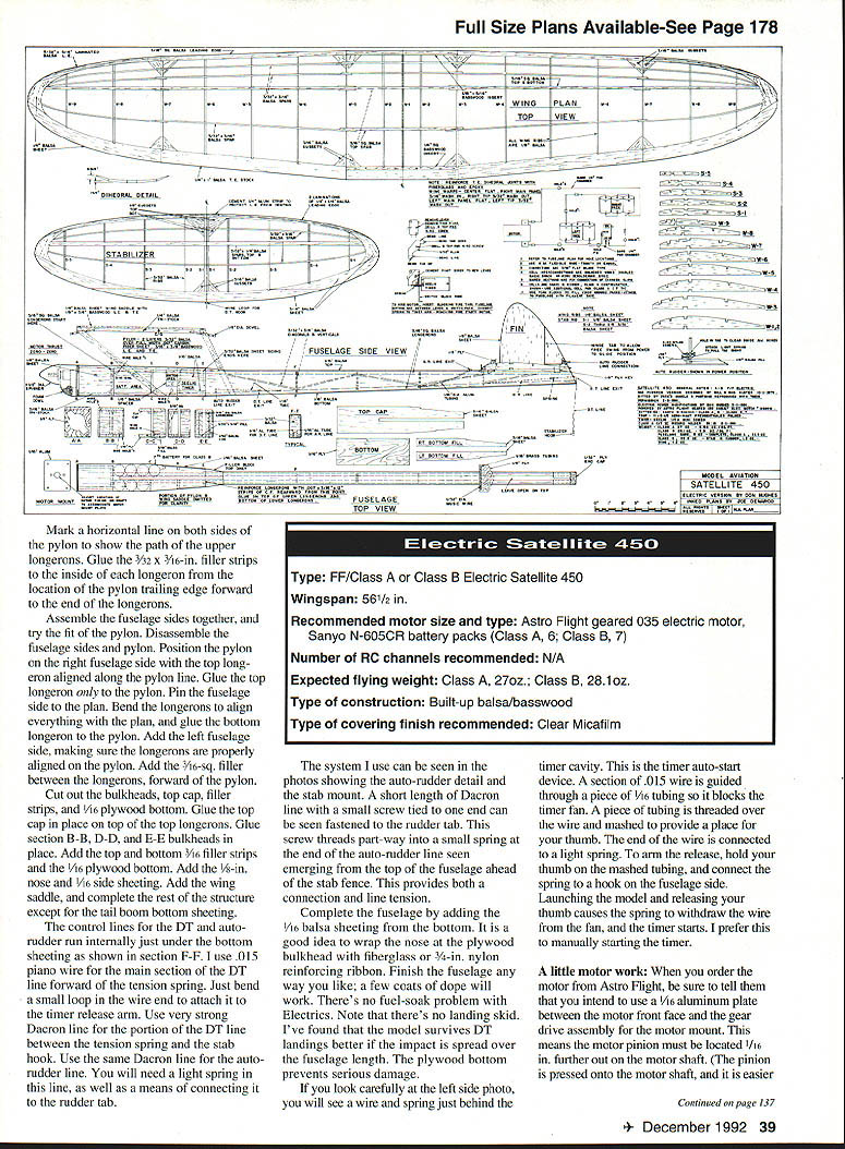
- Type: FF / Class A or Class B electric Satellite 450
- Wingspan: 56-1/2 in.
- Recommended motor: Astro Flight geared 035 electric motor (Free Flight version, catalog 6604G)
- Recommended batteries: Sanyo N-600SCR Ni-Cd cells (Class A: 6 cells; Class B: 7 cells)
- Expected flying weight: Class A: ~27 oz.; Class B: ~28.1 oz.
- Construction: Built-up balsa / basswood (with some carbon-fiber reinforcement)
- Covering: Clear Micafilm (Solarfilm is an alternative)
- Propeller: 11 x 6.6 Aeronaut Freudenthaler propeller assembly
If you are new to FF electrics, start with the six-cell Class A version to gain experience, then build the seven-cell Class B version when you're comfortable. The Satellite 450 kit from Jack's Models is an excellent starting point and, with the electric modifications described here, will give you competitive, reliable performance.
Transcribed from original scans by AI. Minor OCR errors may remain.

