
Electric Sparky
Don Srull
Overview
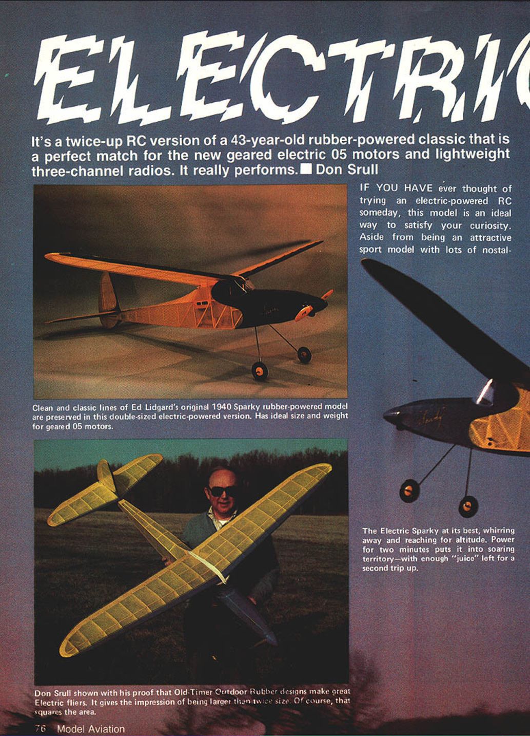
The Electric Sparky is a twice-up radio-controlled (RC) version of a 43-year-old rubber-powered classic, adapted as an ideal match for the new geared .05 electric motors and lightweight three-channel radios. It is an attractive sport model with smooth flight performance, hands-off stability, and respectable thermal-soaring capability.
Ed Lidgard originally designed the Sparky as a high-performance rubber-powered model. The original Sparky (32 in. span, ~115 sq. in. area) was enlarged to suit radio gear and an .05 electric power package. Doubling the size produced a model of about 64 in. span and ~460 sq. in. wing area. The designer estimated an all-up weight near 2½ lb (wing loading ≈ 12½ oz/sq ft); the completed model weighed 43 oz and matched the propulsion system well.
Many Old-Timer rubber designs are well suited to geared electric motors. Most need enlargement for an .05 motor, though some (e.g., the Lanzo Stick) work at original size. These classic designs gain new life with practical motors that can turn large-diameter props.
Construction
- Build the airframe using standard stick-and-tissue techniques and very lightweight balsa. Expected flying weight is 38–42 oz if kept light.
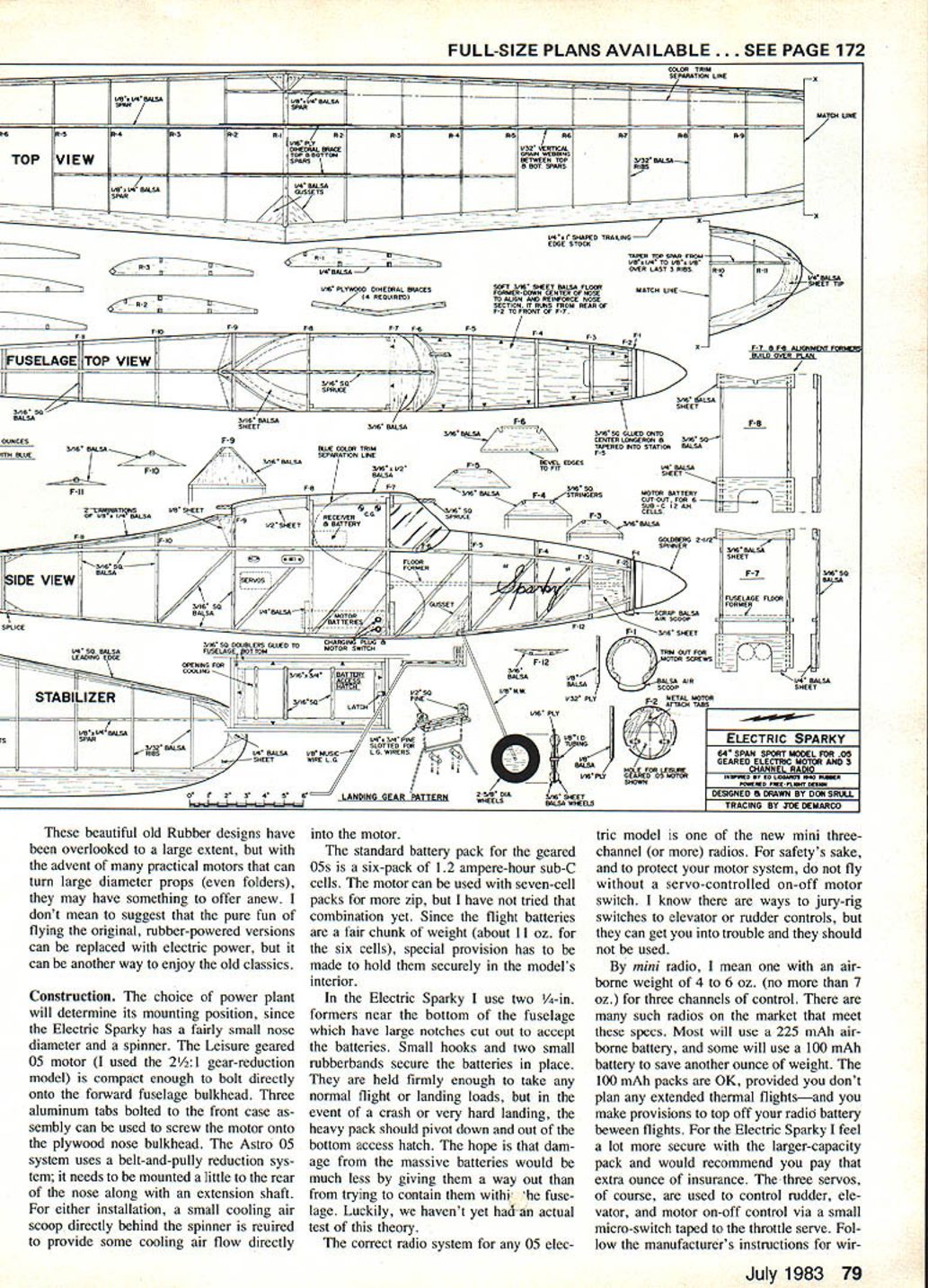
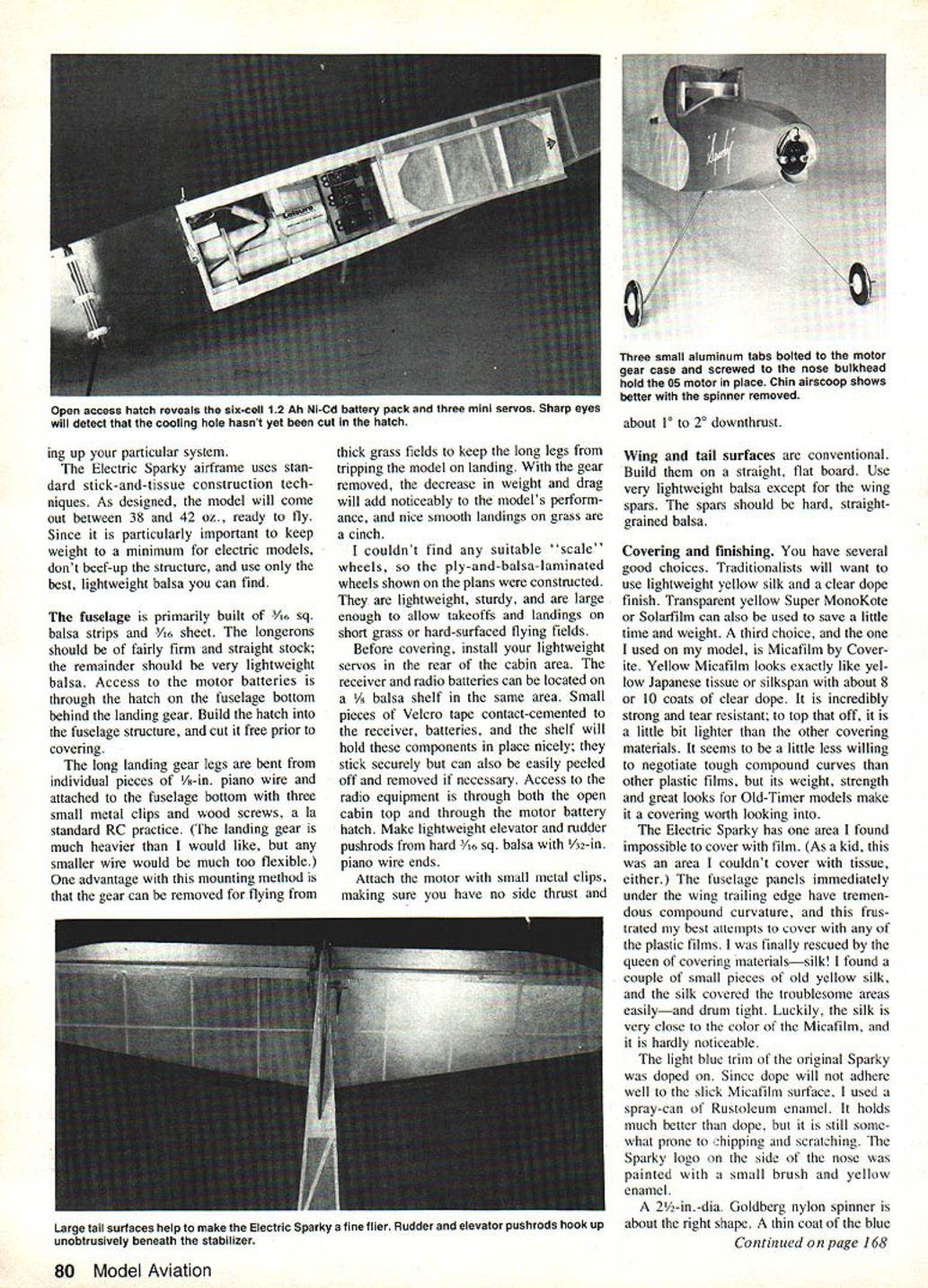
- Fuselage: primarily 1/16-in. sq. balsa strips and 1/16-in. sheet. Use firm, straight grained stock for longerons; very light balsa elsewhere. Install the motor-battery access hatch in the fuselage bottom behind the landing gear and cut it free prior to covering.
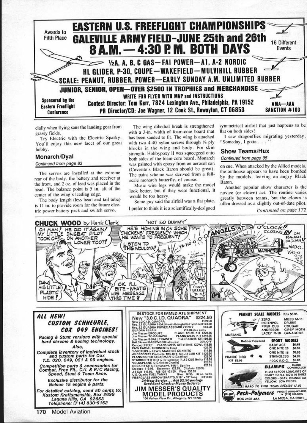
- Wing and tail: conventional construction on a straight, flat board. Use very lightweight balsa except for the spars — those should be hard, straight-grained stock.
- Landing gear: long legs bent from individual pieces of 1/8-in. piano wire, attached to the fuselage bottom with three small metal clips and wood screws (standard RC practice). The gear is removable to aid grass-field operations and improve performance when removed.
- Wheels: build ply-and-balsa-laminated wheels if suitable scale wheels cannot be found; they are lightweight and sturdy.
- Servos and radio gear: install lightweight servos in the rear of the cabin area. Mount receiver and airborne battery on a 1/8-in. balsa shelf. Use Velcro tape to secure components for easy removal. Make lightweight elevator and rudder pushrods from hard 1/16-in. sq. balsa with 1/32-in. piano wire ends.
Powerplant and motor mounting
- The choice of power plant determines mounting, since the Electric Sparky has a fairly small nose diameter and uses a spinner.
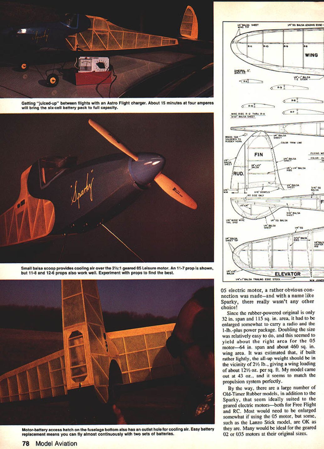
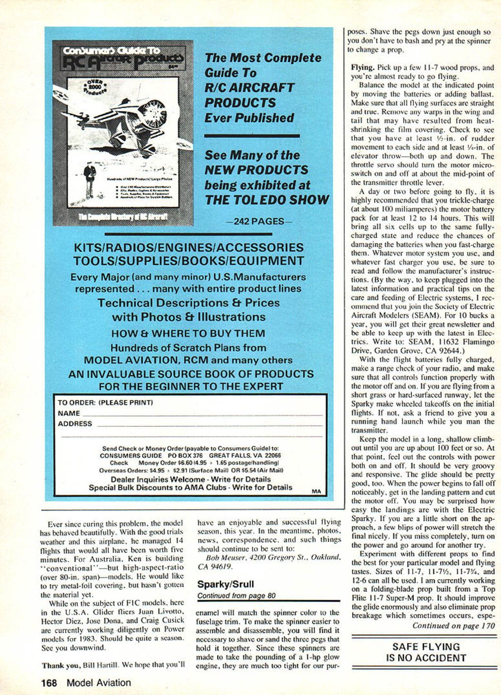
- Leisure geared .05: the compact 2½:1 gear-reduction model can be bolted directly to the forward plywood fuselage bulkhead using three aluminum tabs on the motor case.
- Astro Flight geared system: uses a belt-and-pulley reduction; it needs rearward mounting and an extension shaft.
- For either installation, provide a small cooling air scoop directly behind the spinner to feed cooling air into the motor.
- Attach the motor with small metal clips. Set zero side thrust and about 1°–2° downthrust.
Batteries and mounting
- Standard flight battery is a six-pack of 1.2 Ah sub-C cells (about 11 oz). Seven-cell packs can be used for more power but were not tried here.
- Secure the battery pack: two 1/4-in. formers with large notches accept the batteries. Use small hooks and two small rubber bands to hold the pack. The arrangement is firm for normal flight but allows the pack to pivot down and out through the bottom hatch in a very hard landing or crash—reducing potential damage from the heavy pack.
Radio and controls
- Use a mini three-channel (or more) radio with airborne weight of 4–6 oz (no more than 7 oz). Typical airborne battery: 225 mAh; 100 mAh packs save ~1 oz but limit thermal flight time.
- Three servos: rudder, elevator, and a throttle servo used to operate a servo-controlled on-off motor switch (use a small micro-switch taped to the throttle servo). Do not jury-rig switches to other controls.
- Follow the radio manufacturer’s wiring and antenna-routing instructions.
Covering and finishing
- Covering options:
- Lightweight yellow silk with clear dope (traditional).
- Transparent yellow Super MonoKote or Solarfilm (saves time and weight).
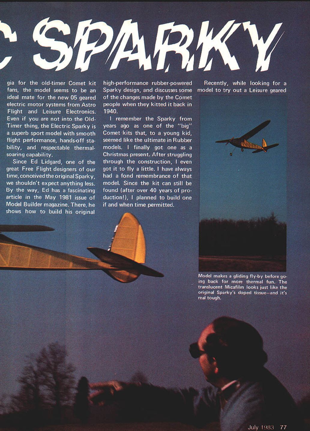
- Micafilm by Coverite (author’s choice): looks like yellow tissue with clear dope, strong, tear resistant, and slightly lighter than other films. It can be less conforming on tough compound curves.
- Problem areas: fuselage panels immediately under the wing trailing edge have pronounced compound curvature. Plastic films may fail here; silk patches are an effective solution and can match Micafilm closely.
- Trim: original Sparky used light blue doped trim. Dope will not adhere to slick Micafilm; use a spray-can enamel (Rustoleum) for trim and small brush-applied enamel for logos.
- Spinner: a 2½-in.-dia. Goldberg nylon spinner is a good match. Sand or shave the assembly pegs slightly so the spinner can be assembled and disassembled without excessive force (these spinners are made for much heavier glow engines and are tight out of the box).
Getting juiced-up between flights
- Charger: an Astro Flight charger at 4 A will bring a six-cell pack to full capacity in about 15 minutes.
- Cooling: provide a small balsa scoop for cooling air over the geared .05 motor. The motor-battery access hatch on the fuselage bottom should include an outlet hole for cooling air.
- Battery swaps: easy battery replacement through the hatch allows near-continuous flying with two packs.
Props and experimentation
- Props that work well: 11×7 (shown), 11×8, 12×6. Other sizes tried include 11×7½ and 11×7¾.
- Experiment with props to find the best performance and glide characteristics. Consider a folding-blade prop (for example, modified from a Top Flite 11×7 Super-M) to improve glide and reduce prop breakage on grass launches.
Flying
- Preflight checklist:
- Trickled-charge the motor battery at ~100 mA for 12–14 hours a day or two before flying to equalize cells.
- Fully charge flight batteries per charger/manufacturer instructions. Read and follow the motor and charger manuals carefully.
- Range-check the radio with flight batteries charged.
- Balance the model at the indicated point by moving batteries or adding ballast.
- Ensure flying surfaces are straight and free of warps from heat-shrinking film.
- Control throws: at least 1/4 in. rudder each side, 1/4 in. elevator up and down.
- Set the throttle servo to switch the motor on/off at about mid-point of the transmitter throttle lever.
- Initial flights:
- For short grass or hard runways, use wheeled takeoffs. Otherwise, use a running hand launch with an assistant.
- Climb in a long, shallow climb to about 100 ft, then feel out the controls with power on and off. The model should be stable and responsive with a good glide.
- When power falls off, enter the landing pattern and cut the motor. Small power blips can stretch a short approach; if missed, reapply power and go around.
- Safety and support: to keep up with developments, consider joining the Society of Electric Aircraft Modelers (SEAM). (SEAM, 11632 Flamingo Drive, Garden Grove, CA 92644.)
Parts and supplies summary
- Geared .05 motor (example: Leisure 2½:1 geared .05 or Astro Flight belt/pulley system)
- Six 1.2 Ah sub-C cells (flight pack, ~11 oz)
- Mini 3-channel radio (4–6 oz airborne weight), 225 mAh airborne battery recommended
- Three lightweight servos (rudder, elevator, throttle/micro-switch)
- 11×7, 11×8, 12×6 props (experiment)
- 2½-in. Goldberg nylon spinner
- Micafilm or lightweight silk for covering
FULL-SIZE PLANS AVAILABLE. SEE PAGE 172.
Transcribed from original scans by AI. Minor OCR errors may remain.

