
Electric Starter
Created just for 1/2A models, this little electric starter is easy to field charge. Joe Beshar
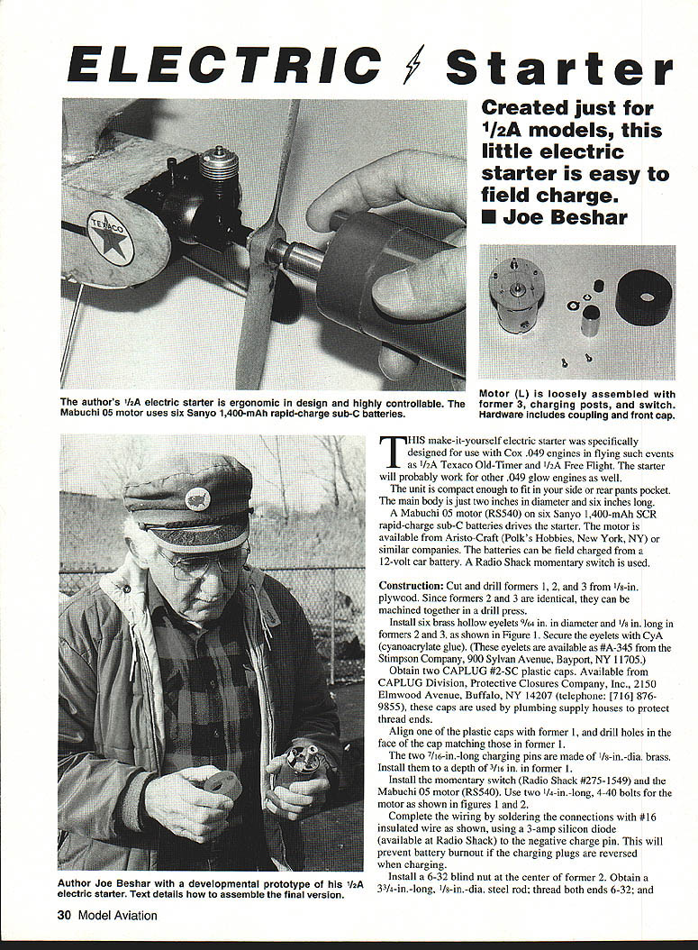
This make-it-yourself electric starter was specifically designed for use with Cox .049 engines in events such as 1/2A Texaco Old-Timer and 1/2A Free Flight. The starter will also work for other .049 glow engines. The unit is compact enough to fit in a side or rear pants pocket: main body is 2 in. in diameter and 6 in. long.
Main components
- Mabuchi 05 motor (RS540)
- Six Sanyo 1,400-mAh SCR rapid-charge sub-C Ni-Cd cells
- Radio Shack momentary switch (Radio Shack #275-1549)
- 3-amp silicon diode (Radio Shack)
- 10-ohm, 5-watt resistor (shrink-wrapped in the negative charging line)
- Brass hollow eyelets (#A-345 from the Stimpson Company)
- CAPLUG #2-SC plastic caps (Protective Closures Co., CAPLUG Division)
- Nutone PVC tubing, 2 in. OD, 1/16 in. wall (available from plumbing suppliers)
- Miscellaneous hardware: dowels, steel rod, blind nut, socket setscrew, rubber tubing, fuel tubing
Construction
- Cut and drill formers
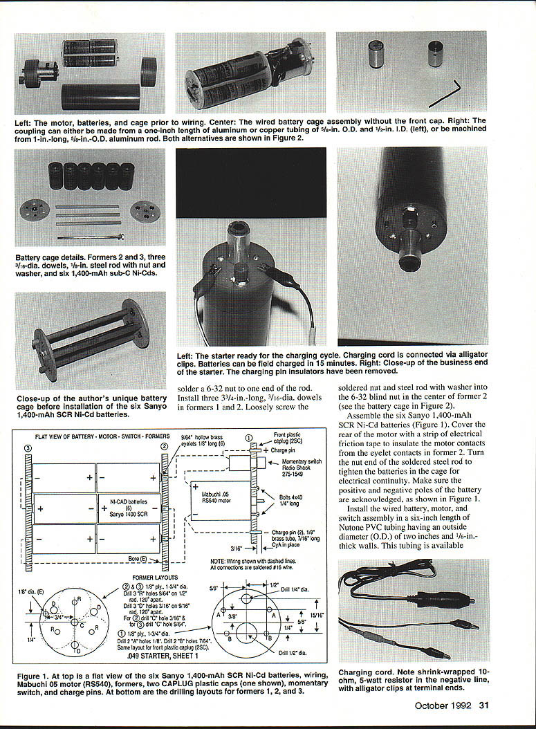
- Cut formers 1, 2 and 3 from 1/8-in. plywood. Formers 2 and 3 are identical and can be machined together in a drill press.
- Install six brass hollow eyelets (9/64 in. dia., 1/8 in. long) in formers 2 and 3. Secure the eyelets with cyanoacrylate (CyA) glue.
- Plastic caps and charging pins
- Obtain two CAPLUG #2-SC plastic caps. Align one cap with former 1 and drill holes in the cap face to match former 1.
- Make two charging pins from 1/8-in.-dia. brass, 7/16 in. long. Install them to a depth of 3/16 in. in former 1.
- Install motor and switch
- Install the Mabuchi 05 motor (RS540) and the momentary switch (Radio Shack #275-1549). Use two 1/4-in.-long, 4-40 bolts to mount the motor.
- Cover the rear of the motor with a strip of electrical friction tape to insulate motor contacts from the eyelet contacts in former 2.
- Wiring
- Complete wiring with #16 insulated wire as shown in the plans. Solder a 3-amp silicon diode to the negative charge pin to prevent battery burnout if charging plugs are reversed.
- Include a shrink-wrapped 10-ohm, 5-watt resistor in the negative charging line.
- Battery cage and retention
- Install a 6-32 blind nut at the center of former 2.
- Obtain a 3-3/4-in.-long, 1/8-in.-dia. steel rod and thread both ends 6-32.
- Solder a 6-32 nut to one end of the rod. Install a nut and washer as shown to retain the battery cage, then solder the nut/rod/washer assembly into the 6-32 blind nut in former 2.
- Install three 3/4-in.-long, 3/16-in.-dia. dowels in formers 1 and 2. Loosely screw the hollow brass eyelets in place and assemble the formers with the dowels and the steel rod.
- Assemble the six Sanyo 1,400-mAh sub-C Ni-Cd cells into the battery cage and wire them in series as required. Turn the nut on the end of the threaded steel rod to compress the battery cage for good electrical contact. Verify positive and negative battery polarity.
- Install assembly into tubing
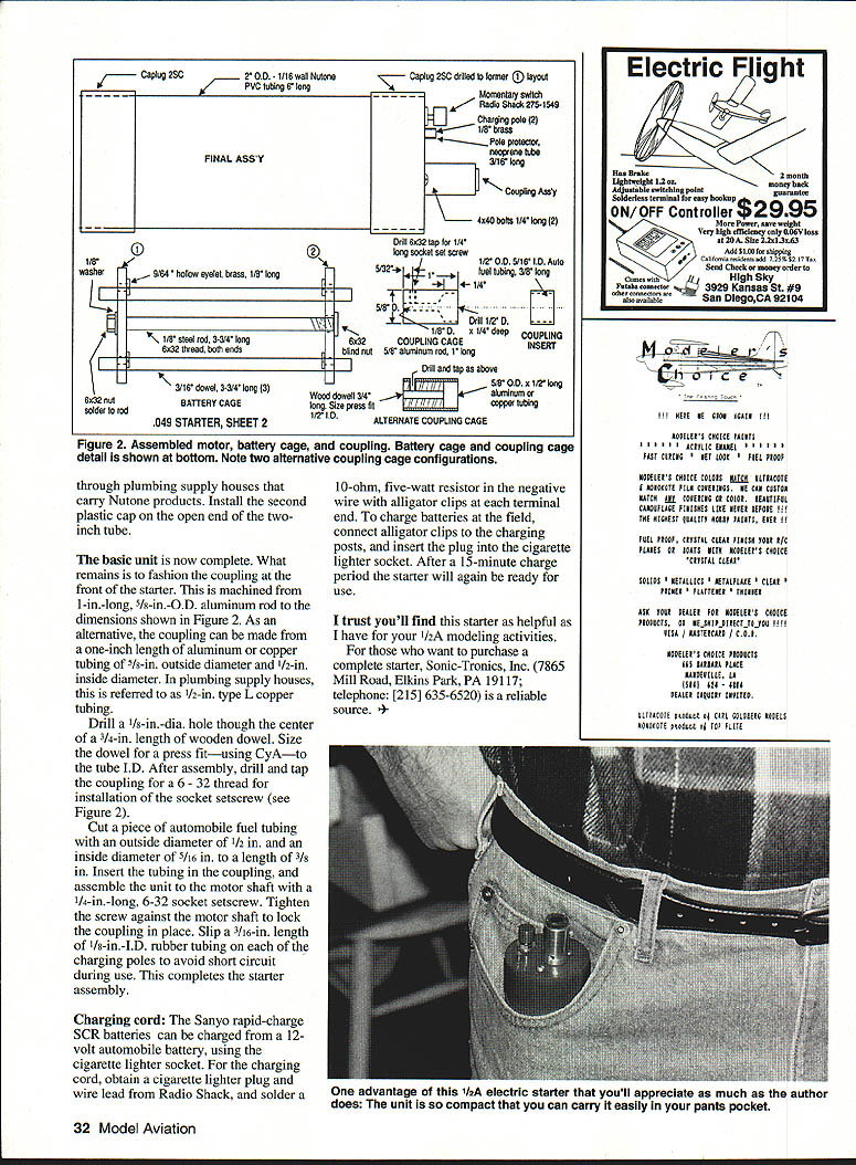
- Install the wired battery/motor/switch assembly into a 6-in. length of Nutone PVC tubing (2 in. OD, 1/16 in. wall). Install the second CAPLUG plastic cap on the open end of the tubing.
- Coupling (front of starter)
- The coupling can be machined from a 1-in.-long, 5/8-in. OD aluminum rod or made from a 1-in. length of aluminum or copper tubing (5/8-in. OD, 1/2-in. ID; plumbing houses refer to this as 1/2-in. type L copper tubing).
- Drill a 1/8-in.-dia. hole through the center of a 3/4-in. length of wooden dowel. Press-fit (with CyA) the dowel into the coupling tube ID.
- Drill and tap the coupling for a 6-32 thread for a 6-32 socket setscrew.
- Cut a piece of automobile fuel tubing (OD 1/2 in., ID 5/16 in.) to 3/8 in. length and insert it in the coupling.
- Assemble the coupling to the motor shaft and secure with a 1/4-in.-long, 6-32 socket setscrew tightened against the motor shaft.
- Slip a 3/16-in. length of 1/8-in. ID rubber tubing over the charging poles to avoid short circuits during use.
- Remove the charging pin insulators before use.
Battery cage details (summary)
- Formers 2 and 3 with three 3/16-in.-dia. dowels, the 1/8-in. steel rod (threaded 6-32), a soldered 6-32 nut and washer, and six 1,400-mAh sub-C Ni-Cd cells form the battery cage.
- Solder the nut and rod into the 6-32 blind nut in the center of former 2, assemble the batteries, cover the motor rear with friction tape for insulation, and tighten the rod nut to compress the battery pack and ensure electrical continuity.
- Verify battery polarity matches the wiring diagram.
Charging cord
- The Sanyo rapid-charge SCR batteries can be charged from a 12-volt automobile battery using the cigarette lighter socket.
- For the charging cord, obtain a cigarette lighter plug and lead (Radio Shack) and solder a 10-ohm, 5-watt resistor in the negative wire. Fit alligator clips to the cord ends for connection to the charging posts.
- To charge at the field: connect alligator clips to the charging posts and insert the cigarette lighter plug into the socket. A 15-minute charge will generally be sufficient to ready the starter.
- A 3-amp silicon diode on the negative charge pin prevents battery burnout if the charging plugs are reversed.
- Remove the charging pin insulators before use.
Suppliers and sources
- Mabuchi motor and Radio Shack parts available from hobby and electronics suppliers.
- Brass hollow eyelets: Stimpson Company, A-345.
- CAPLUG #2-SC: CAPLUG Division, Protective Closures Company, Inc.
- Nutone PVC tubing and 1/2-in. type L copper tubing: plumbing supply houses.
- Complete starter (prebuilt): Sonic-Tronics, Inc., 7865 Mill Road, Elkins Park, PA 19117, telephone (215) 635-6520.
I trust you'll find this starter helpful for your 1/2A modeling activities.
Transcribed from original scans by AI. Minor OCR errors may remain.

