
ELECTRO-LITE
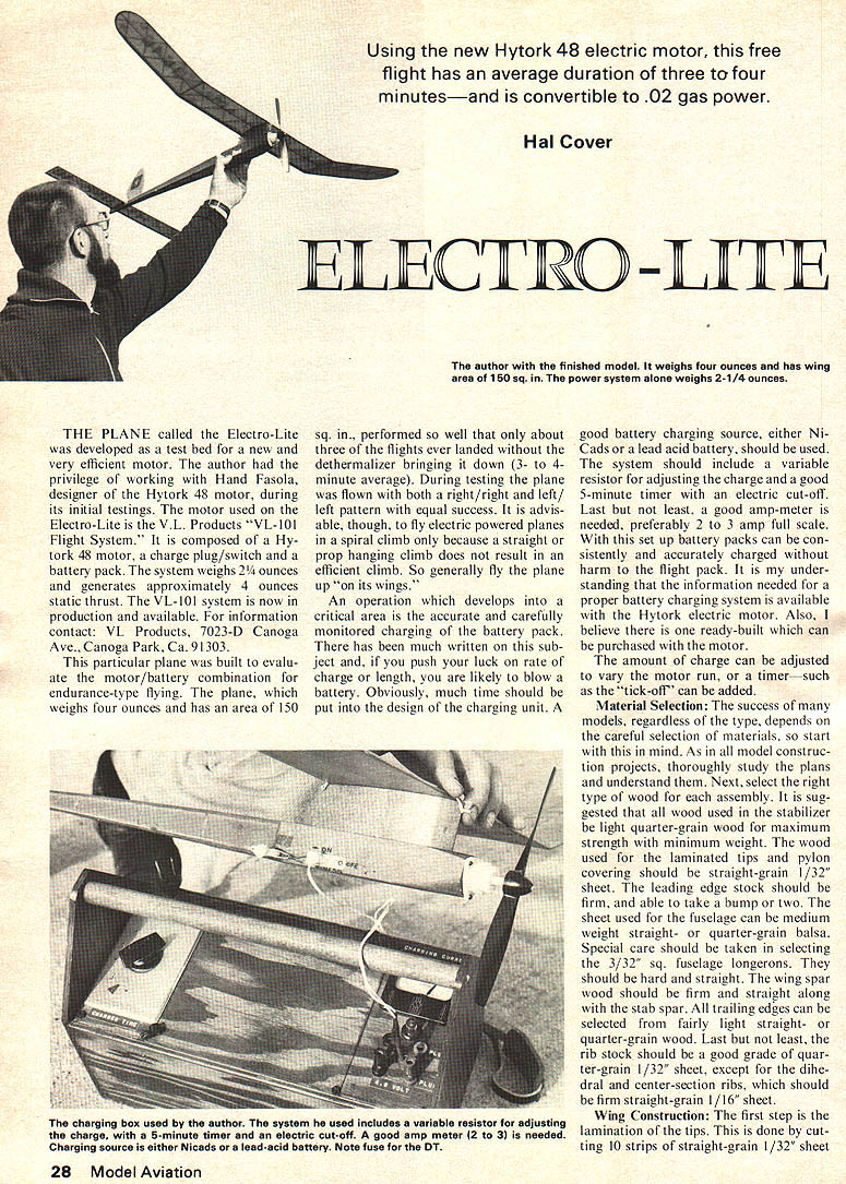
THE PLANE called the Electro-Lite was developed as a test bed for a new and very efficient motor. The author had the privilege of working with Hand Fasola, designer of the Hytork 48 motor, during its initial testings. The motor used on the Electro-Lite is the V.L. Products "VL-101 Flight System." It is composed of a Hytork 48 motor, a charge plug/switch and a battery pack. The system weighs 2-1/4 ounces and generates approximately 4 ounces static thrust. The VL-101 system is now in production and available. For information contact: VL Products, 7023-D Canoga Ave., Canoga Park, Ca. 91303.
This particular plane was built to evaluate the motor/battery combination for endurance-type flying. The plane, which weighs four ounces and has an area of 150 sq. in., performed so well that only about three of the flights ever landed without the dethermalizer bringing it down (3- to 4-minute average). During testing the plane was flown with both a right/right and left/left pattern with equal success. It is advisable, though, to fly electric powered planes in a spiral climb only because a straight or prop-hanging climb does not result in an efficient climb. So generally fly the plane "up on its wings."
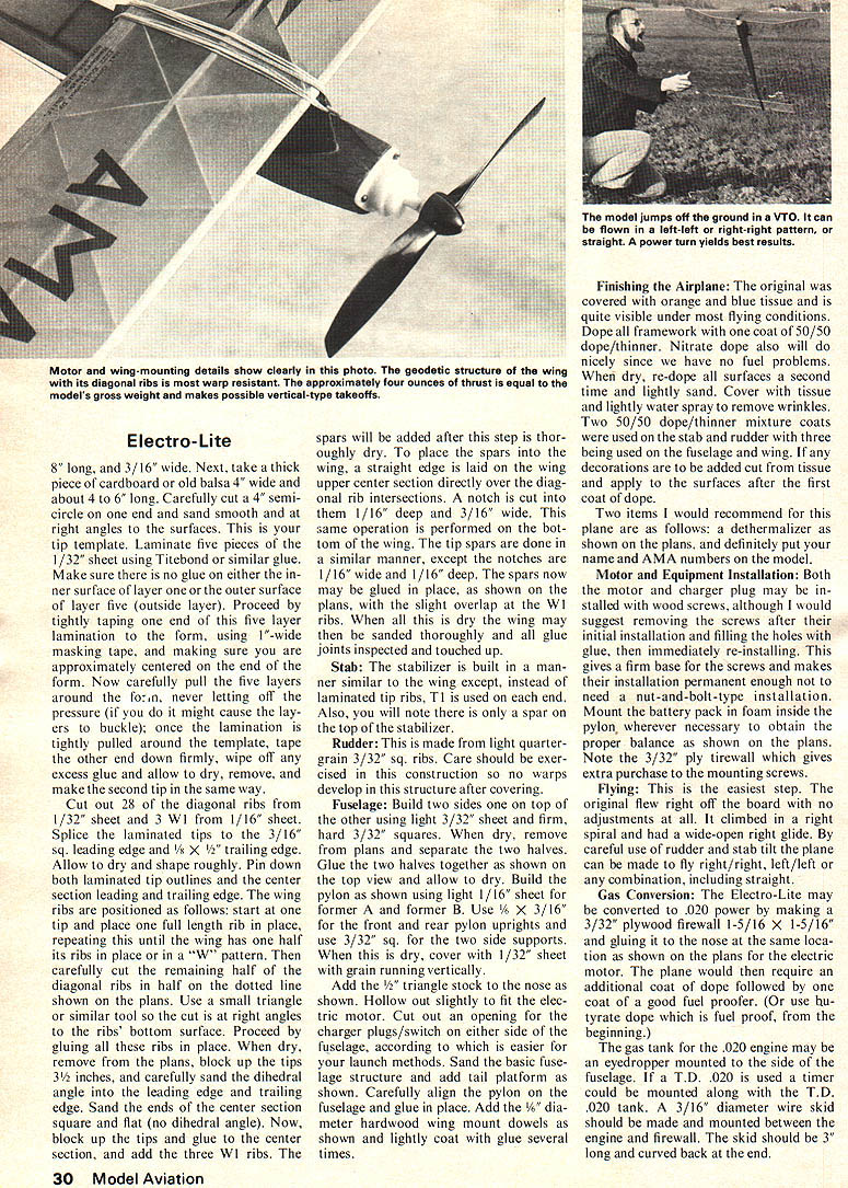
An operation which develops into a critical area is the accurate and carefully monitored charging of the battery pack. There has been much written on this subject and, if you push your luck on rate of charge or length, you are likely to blow a battery. Obviously, much time should be put into the design of the charging unit. A good battery charging source, either Ni-Cads or a lead-acid battery, should be used. The system should include a variable resistor for adjusting the charge and a 5-minute timer with an electric cut-off. Last but not least, a good amp-meter is needed, preferably a 2 to 3 amp full scale. With this set up battery packs can be consistently and accurately charged without harm to the flight pack. It is my understanding that the information needed for a proper battery charging system is available with the Hytork electric motor. Also, I believe there is one ready-built which can be purchased with the motor.
The amount of charge can be adjusted to vary the motor run, or a timer—such as the "tick-off"—can be added.
Material Selection:
The success of many models, regardless of the type, depends on the careful selection of materials, so start with this in mind. As in all model-construction projects, thoroughly study the plans and understand them. Next, select the right type of wood for each assembly. It is suggested that all wood used in the stabilizer be light quarter-grain wood for maximum strength with minimum weight. The wood used for the laminated tips and pylon covering should be straight-grain 1/32" sheet. The leading edge stock should be firm, and able to take a bump or two. The sheet used for the fuselage can be medium weight straight- or quarter-grain balsa. Special care should be taken in selecting the 3/32" sq. fuselage longerons. They should be hard and straight. The wing spar wood should be firm and straight along with the stab spar. All trailing edges can be selected from fairly light straight- or quarter-grain wood. Last but not least, the rib stock should be a good grade of quarter-grain 1/32" sheet, except for the dihedral and center-section ribs, which should be firm straight-grain 1/16" sheet.
Wing Construction:
The first step is the lamination of the tips. This is done by cutting 10 strips of straight-grain 1/32" sheet. Next take a thick piece of cardboard or old balsa 4" wide and about 4 to 6" long. Carefully cut the semicircle at the end and sand smooth the right-angle surfaces to form the tip template. Laminate five pieces of 1/32" sheet using Titebond or similar glue. Make sure no glue is on the inner surface layer. Proceed by tightly taping the ends of the five-layer lamination form using 1"-wide masking tape making sure the lamination is approximately centered on the form. Now carefully pull the five layers around the form, never letting off pressure as this might cause the layers to buckle. Once the lamination is tightly pulled around the template, tape the other end down firmly, wipe off excess glue and allow to dry. Remove and make the second tip the same way.
Cut out 28 diagonal ribs from 1/32" sheet and 3 center-section ribs from 1/16" sheet. Splice the laminated tips to 3/16" sq. leading edge and 1/8" x ? leading edge stock. Allow to dry and shape roughly. Pin down both laminated tip outlines. Center section leading and trailing edge and wing ribs positioned as follows: start at the tip, place the full-length rib, place the next rib and repeat until wing has...
Electro-Lite
been completed. Splice the laminated tips to the 3/16" sq. leading edge and 1/8" x 1/8" trailing edge. Allow to dry and shape roughly. Pin down both laminated tip outlines and the center section leading and trailing edge. The wing ribs are positioned as follows: start at one tip and place one full-length rib in place, repeating this until the wing has one half of its ribs in place or is in a "W" pattern. Then carefully cut the remaining half of the diagonal ribs in half on the dotted line shown on the plans. Use a small triangle or similar tool so the cut is at right angles to the ribs' bottom surface. Proceed by gluing all these ribs in place. When dry, remove from the plans, block up the tips 3/8" inches, and carefully sand the dihedral angle into the leading edge and trailing edge. Sand the ends of the center section square and flat (no dihedral angle). Now block up the tips and glue to the center section, and add the three W1 ribs. The spars will be added after this step is thoroughly dry. To place the spars into the wing, a straightedge is laid on the upper center section directly over the diagonal rib intersections. A notch is cut into them 1/16" deep and 3/16" wide. This same operation is performed on the bottom of the wing. The tip spars are done in a similar manner, except the notches are 1/16" wide and 1/16" deep. The spars now may be glued in place, as shown on the plans, with the slight overlap at the W1 ribs. When all this is dry the wing may then be sanded thoroughly and all glue joints inspected and touched up.
Stab
The stabilizer is built in a manner similar to the wing except instead of laminated tip ribs, T1 is used on each end. Also, you will note there is only a spar on the top of the stabilizer.
Rudder
This is made from light quarter-grain 3/32" sq. ribs. Care should be exercised in this construction so no warps develop in this structure after covering.
Fuselage
Build two sides, one on top of the other, out of the other using light 3/32" sheet and former 3/32" sq. When dry, remove from the plans and separate the two halves. Glue the halves together as shown on the top view and allow to dry. Build the pylon as shown using light 1/16" sheet former A and former B. Use 1/8" x 3/16" for the front and rear pylon uprights and use 3/32" sq. for the two side supports. When this is dry, cover with 1/32" sheet with grain running vertically. Add the 1/2" triangle stock to the nose as shown. Hollow out slightly to fit the electric motor. Cut out an opening for the charger plugs/switch on either side of the fuselage, according to which is easier for your launch methods. Sand the basic fuselage structure and add tail platform as shown. Carefully align the pylon on the fuselage and glue in place. Add the 1/8" diameter hardwood wing mount dowels as shown and lightly coat with glue several times.
Finishing the Airplane
The original was covered with orange and blue tissue and is quite visible under most flying conditions. Dope all framework with one coat of 50/50 dope/thinner. Nitrate dope also will do nicely since we have no fuel problems. When dry, re-dope all surfaces a second time and lightly sand. Cover with tissue and lightly water-spray to remove wrinkles. Two 50/50 dope/thinner mixture coats were used on the stab and rudder with three being used on the fuselage and wing. If any decorations are to be added cut from tissue and apply to the surfaces after the first coat of dope.
Two items I would recommend for this plane are as follows: a dethermalizer as shown on the plans, and definitely put your name and AMA numbers on the model.
Motor and Equipment Installation
Both the motor and charger plug may be installed with wood screws, although I would suggest removing the screws after their initial installation and filling the holes with glue, then re-installing. This gives a firm base for the screws and makes their installation permanent enough not to need a nut-and-bolt type installation. Mount the battery pack in the foam inside the power pan where it is necessary to obtain the proper balance as shown on the plans. Note the 3/32" ply firewall which gives extra purchase to the mounting screws.
Flying
This is the easiest step. The original flew right off the board with no adjustments at all. It climbed in a right spiral and had a wide-open right glide. By careful use of rudder and stab tilt the plane can be made to fly right/left, right/left/right, left/right/left or any combination, including straight.
Gas Conversion
The Electro-Lite may be converted to .020 power by making a 3/32" plywood firewall 1-5/16" and gluing it to the nose at the same location as shown on the plans for the electric motor. The plane would then require an additional coat of dope followed by one coat of a good fuel proofer. The gas tank for the .020 engine may be mounted to the side of the fuselage. If a T.D. .020 is used a timer could be mounted along with the T.D. .020 tank. A 3/16" diameter wire skid should be made and mounted between the engine and firewall. The skid should be 3" long and curved back at the end.
Transcribed from original scans by AI. Minor OCR errors may remain.

