
Electrocutor
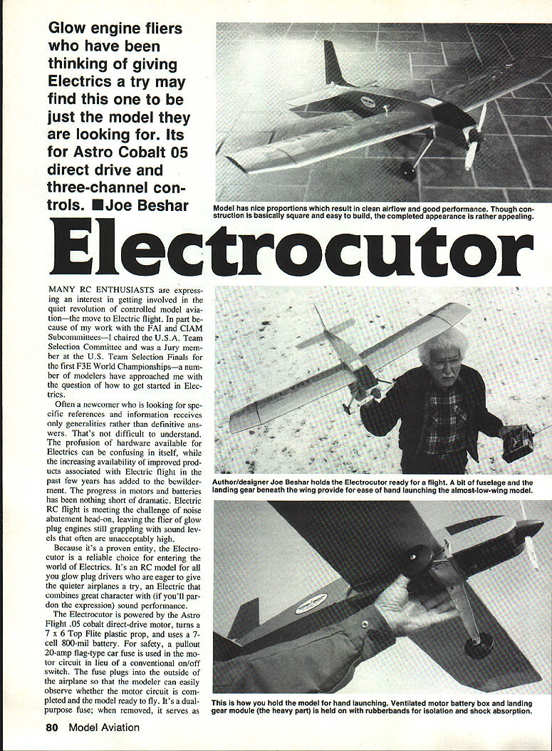
Glow-engine fliers who have been thinking of giving electrics a try may find this one to be just the model they are looking for. It's designed for the Astro Cobalt .05 direct-drive motor and three-channel controls. — Joe Beshar
MANY RC enthusiasts are expressing an interest in getting involved in the quiet revolution of controlled model aviation—the move to electric flight. In part because of my work with the FAI and CIAM subcommittees—I chaired the U.S.A. Team Selection Committee and was a jury member at the U.S. Team Selection Finals for the first F3E World Championships—a number of modelers have approached me with the question of how to get started in electrics.
Often a newcomer who is looking for specific references and information receives only generalities rather than definitive answers. That's not difficult to understand. The profusion of hardware available for electrics can be confusing in itself, and the increasing availability of improved products associated with electric flight in the past few years has added to the bewilderment. The progress in motors and batteries has been nothing short of dramatic. Electric RC flight is meeting the challenge of noise abatement head-on, leaving the flier of glow-plug engines still grappling with sound levels that often are unacceptably high.
Because it's a proven entity, the Electrocutor is a reliable choice for entering the world of electrics. It's an R/C model for glow-plug drivers who are eager to give the quieter airplanes a try—an electric that combines great character with (if you'll pardon the expression) sound performance.
The Electrocutor is powered by the Astro Flight .05 cobalt direct-drive motor, turns a 7 x 6 Top Flite plastic prop, and uses a 7-cell 800-mil battery. For safety, a pullout 20-amp flag-type car fuse is used in the motor circuit in lieu of a conventional on/off switch. The fuse plugs into the outside of the airplane so that the modeler can easily observe whether the motor circuit is completed and the model ready to fly. It's a dual-purpose fuse; when removed, it serves as a safety switch.
The model has nice proportions, resulting in clean airflow and good performance. Though construction is basically square and easy to build, the completed appearance is rather appealing.
Author/designer Joe Beshar holds the Electrocutor ready for flight. The fuselage and landing gear beneath the wing provide ease in hand launching. As an almost low-wing model, hold the model by the fuselage for hand launches.
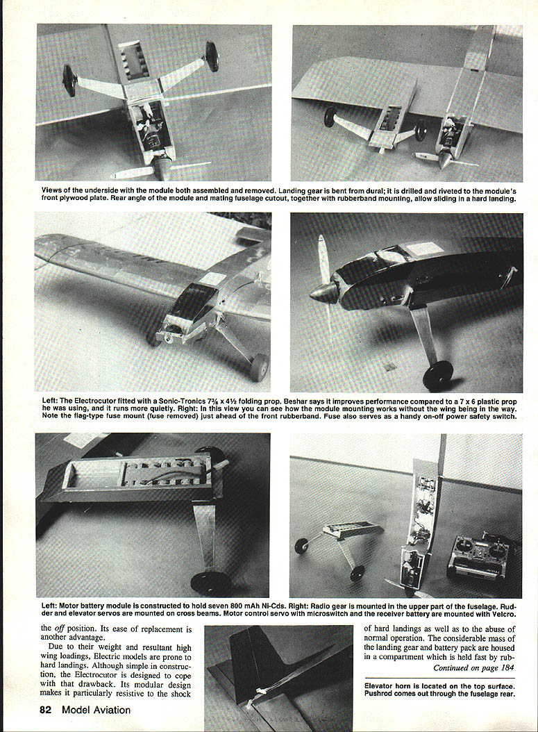
The motor/battery box is ventilated. The landing-gear module and other heavy parts are held in place with rubber bands to provide isolation and shock absorption. The landing-gear module's ease of replacement is another advantage.
Due to their weight and resultant high wing loadings, electric models are prone to hard landings. Although simple in construction, the Electrocutor is designed to cope with that drawback. Its modular design makes it particularly resistant to the shock of hard landings as well as to the abuse of normal operation. The considerable mass of the landing gear and battery pack is housed in a compartment which is held fast by rubber bands and thus completely isolated from the fuselage and primary structure. The elasticity of the rubber bands also helps the landing-gear/battery-pack module absorb the impact of a hard landing.
The Electrocutor's midwing configuration is fairly unique; most electrics are of high-wing configuration. The polyhedral wing provides exceptional stability that will be readily recognized when you fly the model. The aircraft is very responsive to the controls, giving it outstanding flight characteristics and making it an ideal first-time electric R/C model.
As with any electric model, it's vital that the motor battery be charged properly to full capacity. For general, everyday flying, I find an automatic-reversing charger the best way to go. With the Electrocutor, this type of charger yields more than adequate power for flight maneuverability as well as for takeoff. Three servos are employed for the controls:
- motor on/off
- rudder
- elevator
A 250-milliamp radio receiver power-supply battery is used.
Much has been done to reduce the flight weight of electric models, but further reductions are necessary. With the aggressive technological improvements being pursued by industry, I am confident that this will be achieved before very long. I think we're on the doorstep of a future in which the full excitement of electric flight can be realized.
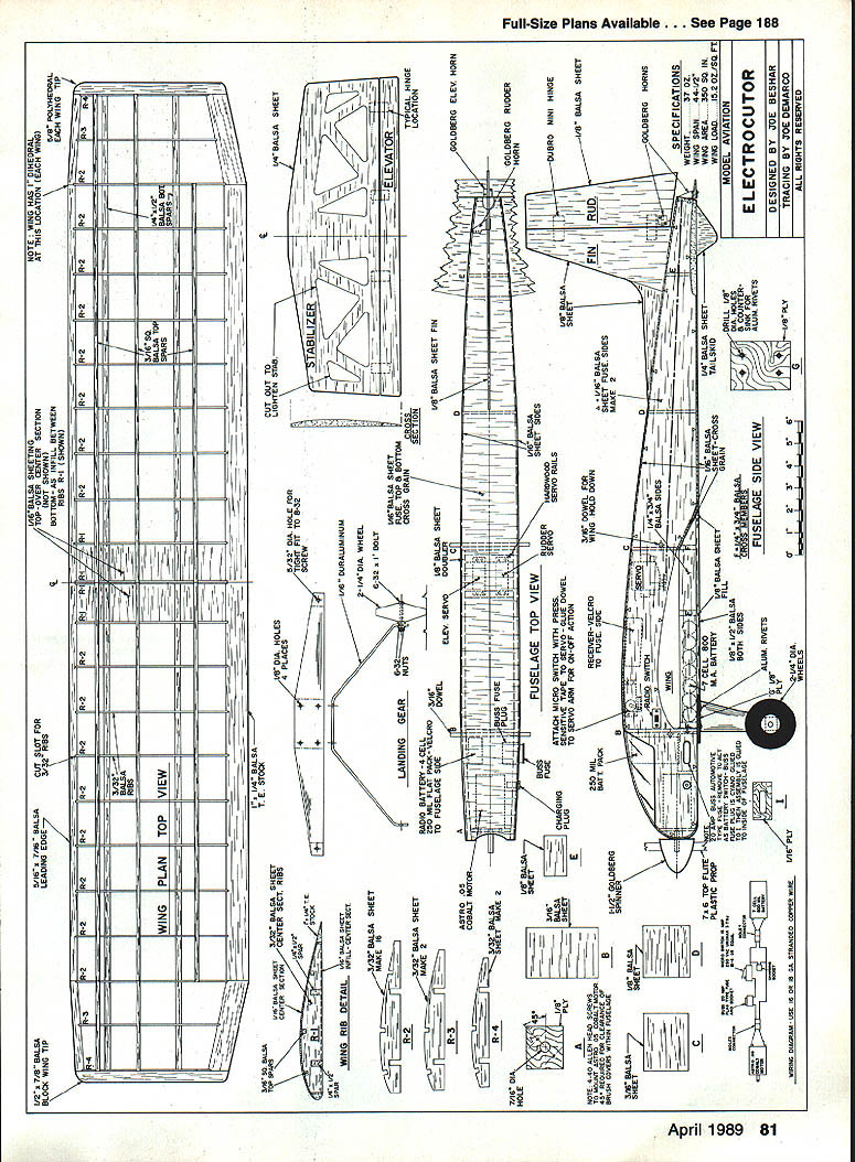
Fuselage
The primary construction material for the fuselage is 1/8" sheet balsa. On the plan, triangular symbols are used to indicate the side templates. Cut formers B, C, D, and E from 3/16" and 1/8" balsa as shown. Former A is cut and drilled for mounting the Astro Flight .05 motor. Position the side templates and formers over the top view of the plan, and glue the formers with cyanoacrylate (CYA) or epoxy, as desired.
Install the control horns at the locations shown. The hinges are glued with CYA after covering the model.
Cut a slot at the top of the fuselage, glue the rudder assembly in place, then glue the elevator to the bottom cutout of the original template. Align the elevator and rudder for Sullivan-type pushrods, punching 1/16-in. holes through formers C, D, and E, as applicable for attachment of the pushrods to the horns and servo arms. CYA, sprinkled with baking powder, is used to glue the pushrods (which have been roughened) to the formers. If desired, the 2-1/4-in. wheels may be turned from balsa, with drilled dowel bushings at the axle location; otherwise, the wheels may be purchased.
Sheet the bottom of the fuselage with 1/16-in. balsa. Install the charging plug and wire the electric motor circuit.
Wing, Rudder, and Elevator
The wing leading edges are made from 3/16 x 7/16-in. balsa, the trailing edges from 1/4 x 1-in. balsa. Each is slotted for 3/32-in. ribs as shown.
Cut the ribs from 3/32-in. balsa (the center ribs 1, 1A, 2, 2A, the main ribs, and two each of tip ribs 11 and 12). Pin the slotted leading and trailing edges to the plan with 1/4 x 2-1/2-in. spars. Assemble and glue all the ribs, with the exception of 1, 1A, and 10. Taper and fit the leading edge, trailing edge, and spars at location 10, and develop the 5/8-in. polyhedral. Position rib 10 on both sides of the wing, and glue. Taper and fit the leading edge, trailing edge, and spars as necessary at the center section to accommodate 1 in. of dihedral. Glue ribs 1 and 1A in place.
Install the 3/32-in.-sq. top spars, fitting them as necessary. Use 1/8-in. balsa sheet for the center section of the wing between ribs 2 and 3A as shown on the plan. Glue on the 1/8 x 7/8 x 7-in. balsa tip blocks in position. Plane, trim, and sand the trailing and leading edges, tip blocks, spars, and sheet as necessary to create the airfoil illustrated.
I covered the prototype with MonoKote, which has served very satisfactorily.
Once completed, your Electrocutor should provide a terrific excuse to join the quiet revolution of electric flight. I trust you'll find the model as enjoyable as I have.
Transcribed from original scans by AI. Minor OCR errors may remain.

