
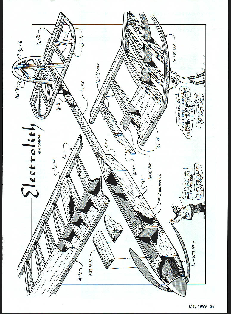
Electrolith
Ken Cashion
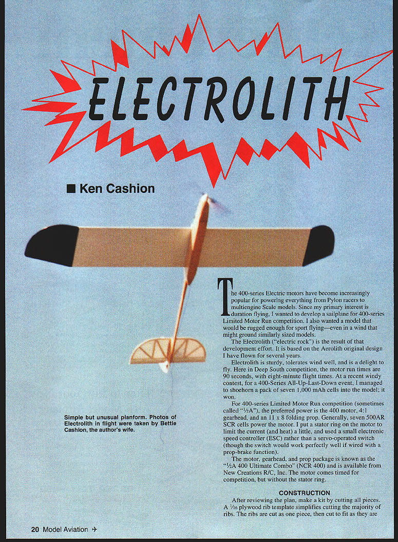
The 400-series electric motors have become increasingly popular for powering everything from pylon racers to multiengine scale models. Since my primary interest is duration flying, I wanted to develop a sailplane for 400-series Limited Motor Run competition. I also wanted a model that would be rugged enough for sport flying—even in winds that might ground similarly sized models.
The Electrolith ("electric rock") is the result. It is based on the Aerolith original design I have flown for several years. Electrolith is sturdy, tolerates wind well, and is a delight to fly. Here in the Deep South competition, motor run times are 90 seconds with eight-minute flight times. At a recent windy contest, for a 400-Series All-Up-Last-Down event, I managed to shoehorn a pack of seven 1,000 mAh cells into the model; it won.
For 400-series Limited Motor Run competition (sometimes called "4A"), the preferred power is the 400 motor, 1:1 gearhead, and an 11 x 8 folding prop. Generally, seven 500AR SCR cells power the motor. I put a stator ring on the motor to limit the current (and heat) a little, and used a small electronic speed controller (ESC) rather than a servo-operated switch (though the switch would work perfectly well if wired with a prop-brake function).
The motor, gearhead, and prop package is known as the "1/4A 400 Ultimate Combo" (NCR 400) and is available from New Creations R/C, Inc. The motor comes timed for competition, but without the stator ring.
Specifications
- Type: RC sailplane
- Wingspan: 57 in
- Motor: Speed 400
- Functions: Rudder, elevator, motor
- Flying weight: 26 oz
- Construction: Built-up
- Covering/finish: Film on flying surfaces; lacquer on fuselage
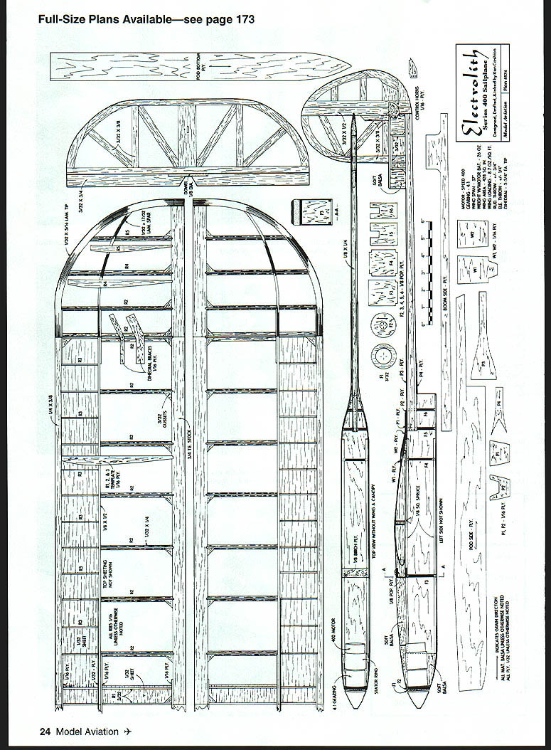
Full-Size Plans Available—see page 173
Construction
After reviewing the plan, make a kit by cutting all pieces. A 1/16" plywood rib template simplifies cutting the majority of ribs. Cut ribs as one piece, then trim to fit as they are laid out on the wing plan. Cut F1, F2, P1, P2, P3, P4, and the pod bottom slightly oversize and trim for proper fit after assembly.
Hobbico Bullet thick and thin cyanoacrylates (CyA) and accelerator were used exclusively.
Empennage
- Build all parts over the plan using hard balsa for leading edges (LE), fin/rudder spars, and stab center. Use soft balsa elsewhere, especially for the elevator.
- Before cutting rudder clearance in the elevator, inset and sand the dowel to the thickness of the elevator.
Wing
- Lay out the wing plan so the center section can be constructed in one piece. Cut rib notches in the trailing edge (TE).
- Secure the TE, bottom center sheeting, bottom LE sheeting, spar, lower capstrips, and LE (to be shaped later). There should be no break in the center sheeting at the wing center. Add center plywood braces.
- Cut ribs to fit between LE, spar, and TE, and start gluing ribs in place; leave dihedral ribs until after the tips are joined to the center section.
Wingtip lamination:
- Cut 24 strips (12 per tip) of 1/32" x 3/8" x 14" balsa.
- Make a wingtip former and cover with plastic wrap. Rubber-band the first strip over the former, add one 1/2 strip at a time, gluing each in turn with CyA and accelerator. This produces a very light, slightly oversize, rigid LE. Sand the nominal 3/8" tip to 5/16".
- Tip spars: use four strips of 1/32" x 5/8" x 9" per tip; sand the nominal 5/16" to 7/32".
Tip assembly:
- Cut ends of laminated tips and spars to length and secure to the plan. Cut and secure lower capstrips and tip ribs to fit. Mark LE, spar, and ribs; remove the lower spar (LB) from the plan and taper both spars to rib height. The LE should be about 1/32" higher than the ribs; the lower spar (LB) should be 3/32" higher than the ribs.
- Glue tip TE, spar, and three tip ribs in place, leaving the dihedral rib for later. Add upper capstrips and tip ribs. Add TE/rib gussets to tips and center section. Remove wing sections from the board.
Shaping and dihedral:
- Place the wing center section LE edge on a table and plane/shave/sand excess from the top LE to approximate finished shape. The upper LE material must follow basic rib curve before sheeting is applied.
- Cut plywood dihedral braces and support tips to correct dihedral. Trim LE, spar, and TE dihedral joints to mate and secure dihedral braces to the center section. After confirming dihedral, secure tips to the center section.
- Cut CyA dihedral ribs and place capstrip top and bottom of the dihedral rib — eight total per wing — making the dihedral joint 1/2" wide to facilitate covering. Secure the wing to the building board again. Confirm joints are firm and aligned. Glue center sheeting and capstrips. Remove the wing board and final-shape the LE.
Before covering:
- Remove a small amount of material on the upper edge of the tip spars between ribs so tightened covering will not contact the upper edge and interrupt tip airflow. Fairings on LE and TE will be added later.
Fuselage
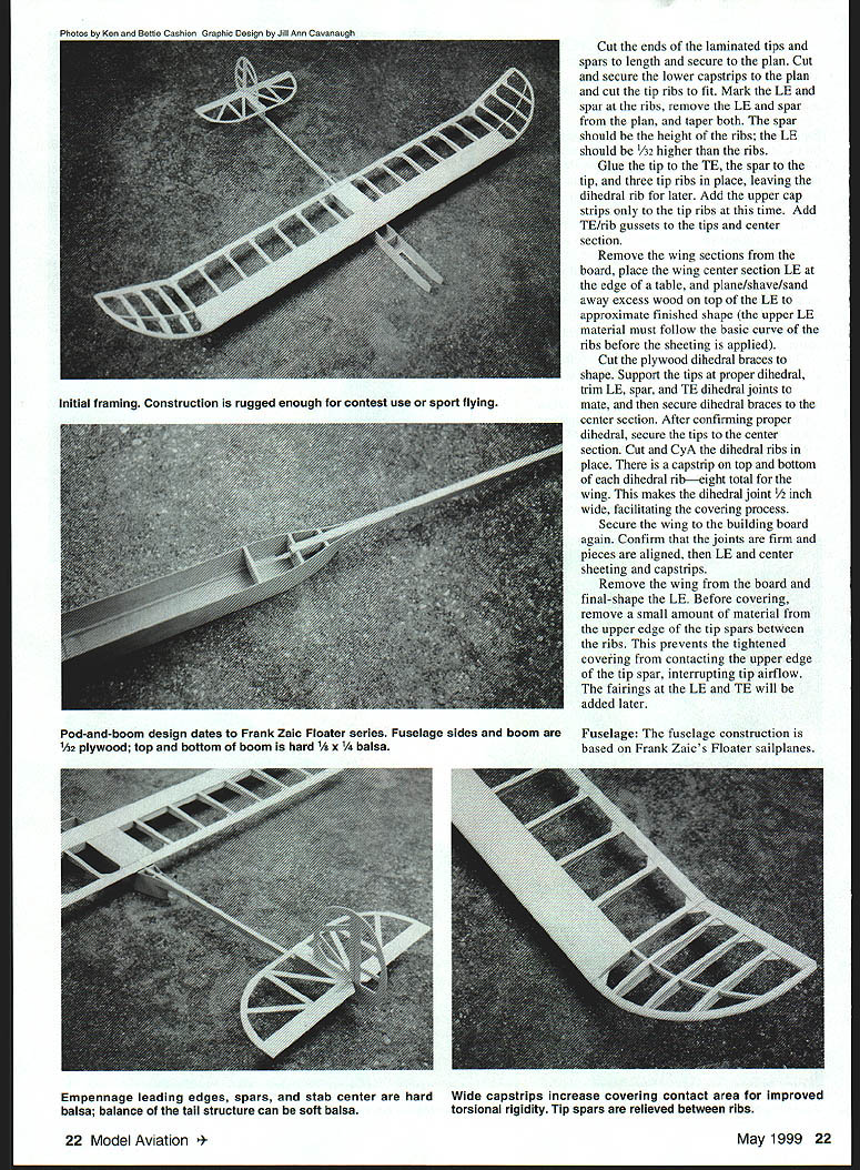
The fuselage construction is based on Frank Zaic's Floater sailplanes. The pod-and-boom design provides a small frontal area with good strength and generous equipment volume—important for electric models.
Materials and framing:
- Fuselage sides and boom: 1/32" (or 3/32" as preferred) plywood.
- Pod formers F2–F6: 1/8" Lite Ply (or 3/32" Lite Ply).
- Top and bottom boom strips: hard 1/8" x 1/4" balsa.
- Empennage leading edges, spars, and stab center: hard balsa. Wide capstrips increase covering contact area and improve balance. Tail structure may use soft balsa where torsional flexibility is desirable. Tip spars should be relieved between ribs.
Build notes:
- If a natural finish is desired, accurate building and limited sanding will prevent exposing plywood veneers; leave outer veneers except in streamlined areas for appearance.
Boom
- Shape hard balsa top and bottom strips. At the aft end, hold one boom side flat on the building surface and glue the strips in place. Try to press the aft ends of the boom strips together while the glue sets.
- Decide on pushrod method now. If using tubes, lay tubes in and secure in a few places; they should be overlength and trimmed later. Use proper CyA or epoxy on plastic tubing.
- Glue the other boom side with the boom still held flat. Press and shape aft boom sides and glue in place.
- Glue small pieces of 3/32" balsa in the plywood stab support, then fair the front and back with soft balsa. Confirm the top of the stab support and the top of the boom are parallel — this sets the incidence at the fuselage/wing saddle.
Pod
- Glue 1/8" square spruce longerons (do not use balsa) to the pod sides. By this time determine servo size/location and the actual location of F4 so minimum-size clearance holes can be cut in F3 and F4. Also plan where other gear will be installed.
- While the pod bottom is secured on a flat surface, confirm boom notches in F5 and F6 are on the centerline and that formers contact the pod bottom. Glue F3–F6 in place.
- Trial-fit pod sides to the pod bottom, then glue pod sides to F3 and F4 simultaneously to maintain symmetry; avoid twisting. Slightly oversize pod bottom is acceptable — trim later.
- Compress lower aft pod sides to touch at the rear behind F6, bevel inside plywood edges to fit when compressed, then join with thick CyA (use accelerator). If alignment is true, reinforce joints with additional CyA.
Nose and boom fit:
- Shape outside surfaces of the balsa blocks to conform to the plan, glue blocks to the pod and nose block. Keep the nose cross section square. Pull the pod top apart, glue the top, and let set. Fit and glue the nose block to the pod front. Add small fillets and let set.
- Fit the boom into pod notches of F5 and F6 and confirm the boom is straight and aligned to the pod centerline from above and side. The pod bottom and boom top should be parallel. Secure the boom to formers with liberal CyA and accelerator to build small fillets. Do not glue pod sides to the boom yet. If small misalignment occurs, trim the stab support before empennage attachment. After confirming symmetry, glue the sides to the boom.
Servos and wing hold-down:
- Install servo rails and temporarily install control rods to determine servo locations; cut minimum-size clearance holes in F3 and F4. Install servos, saving rod installation for later. Use as little space as possible for servos to maximize room for battery packs and RC gear.
- Cut the birch plywood wing hold-down piece and glue in place. Fit pod fairings P3 and P4 and glue. Trim excess material later to match sides and bottom.
- Place the wing on the fuselage and check alignment. Position W1 at the top center TE and glue in place (note grain direction; W1 will need to flex slightly for wing installation). Draw the outline of the W1 tab on top of P3. Trim P2 to clear this tab and glue P2 in place. Glue P1 to P2 and trim edges to fit. Check wing alignment and tab fit in the rear pod slot. Trim and sand W1 for proper fit/alignment. Mark position for W2 on top of W1, remove the wing, and glue W2 in place. Remove excess material from fairings as needed.
Motor and nose fairing:
- Hollow a balsa nose block for a snug slip-fit of motor and gearhead. Secure F2 to the motor using two small screws into the gearhead. Slip the motor, with F2 attached, into the fuselage to test fit and alignment. Trim the fuselage nose block for a flush fit with F2. Using a tiny amount of CyA, secure F2 to the fuselage. Remove and reinstall the motor through the cockpit area to confirm fit and clearances. After final confirmation, add more CyA to secure F2; then glue F1 to F2.
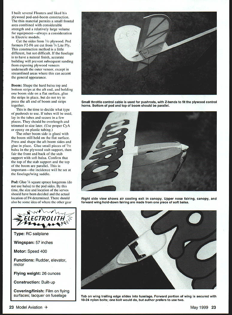
- The upper nose fairing, canopy, and forward wing hold-down fairing are constructed from one piece of soft balsa. Confirm the top forward fuselage from wing LE to nose is flat and trim where necessary. Cut and shape the balsa piece to match the fuselage from wing to nose and make it long enough to overlap a small portion of the wing LE. Remove material from the rear of the fairing to match LE sheeting and provide motor clearance under the nose fairing if required. Temporarily glue the fairing.
- Cut the poplar plywood wing fairing piece slightly long, mark its location on the top fairing, cut the slot, and CyA it in place. Draw the spinner diameter on F1 and start shaping the nose as indicated on the plan and photos. When satisfied, sand the fuselage and cut the piece free from the fuselage. Cut this piece into three parts: top nose fairing, canopy, and forward wing fairing.
Final pod details:
- Glue the nose fairing to the fuselage. Set the canopy and wing fairing in place, position the wing in proper alignment on the fuselage, and glue the wing fairing to the wing. Leave enough clearance at canopy ends so covering material will not bind the canopy during installation. Remove excess material from inside the canopy and cut motor cooling vents.
- Set the wing with proper alignment and drill through the wing fairing and wing hold-down brace with a #25 (3/32") drill as shown on the plan. Remove the wing and harden brace holes with CyA. Tap holes for 10-24 nylon screws. Make screw clearance holes in the wing fairing with a #12 (3/64") drill.
Preassembly:
- Trial-fit the fin and stab and check alignment. Trim the stab support until satisfied and mark mating outlines so these areas can be left free of covering for a strong bond. Install servo and empennage control horns. Pin empennage in place and temporarily install pushrods to determine aft rod/horn neutral locations. Make all pushrod connections and leave forward ends long for final trimming. Remove the empennage for covering.
Covering
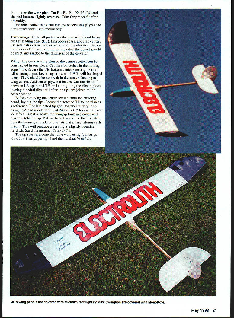
- I use Coverite Micafilm almost exclusively on electric sailplane wings and empennage because airspeed can become excessive and torsional rigidity is essential. Use rather wide capstrips to increase covering bonding surfaces and make the wing more rigid. MonoKote was used on the wingtips.
- Always secure covering where it contacts structure; it should be part of the structure, not just a shiny plastic bag around the parts. A small amount of balsa or balsa veneer will feather edges where plywood surfaces overlap. To get a good plywood finish, hold a single-edge razor nearly vertical and drag with the grain to remove the tiniest bit of wood—this produces a smooth, hard surface.
- My fuselage received several light spray coats of fast-drying clear lacquer. When the bottom gets scuffed, sand lightly and respray. Other finishing materials may be used as desired.
Final Assembly
- Hinge the empennage (I used MonoKote strips), fit the vertical tail into the horizontal tail and set both on the stab support. When aligned, secure with CyA.
- Install pushrods and attach aft ends to control horns. Position control surfaces to neutral and mark forward pushrod ends at servo horns. Cut rods to length and complete servo ends.
- Install motor, prop, and spinner. Install receiver and motor controller. By moving the flight battery (I use a 270 mAh pack) and motor batteries fore and aft, determine locations to balance the model as shown on the plan. Install the switch.
Notes on motor control:
- When power is removed from a 4:1 gearhead and an 11" prop in flight, the prop will continue to windmill unless the motor has braking capability. If a servo/switch arrangement is used for motor control, ensure a prop-brake arrangement on the switch. If an ESC is used, it must have a prop-brake feature.
- I do not recommend using battery eliminator circuits (BECs) unless the model is for scale or general sport. With duration models, it is easy to keep flying long after a battery can no longer power the motor; if the receiver loses power, problems can follow.
- Make motor controller, servo, and range tests with the prop removed.
Flying
With the control surface throws as shown on the plan and the CG positioned as indicated, the model will fly right from your hand and start a gentle climb. Be ready to press in a little down elevator should it start to balloon.
What follows for the rest of the flight is the flying fun for which you built the Electrolith.
Ken Cashion 157 Tennyson Cove Picayune, MS 39466 kcashion@datasync.com
Sources
- New Creations R/C, Inc.
Box 496 Willis, TX 77378 (409) 856-4630
- Hobbico products are available from Tower Hobbies.
Transcribed from original scans by AI. Minor OCR errors may remain.

