

Electronic Sync System for Twins
Joseph G. Utasi
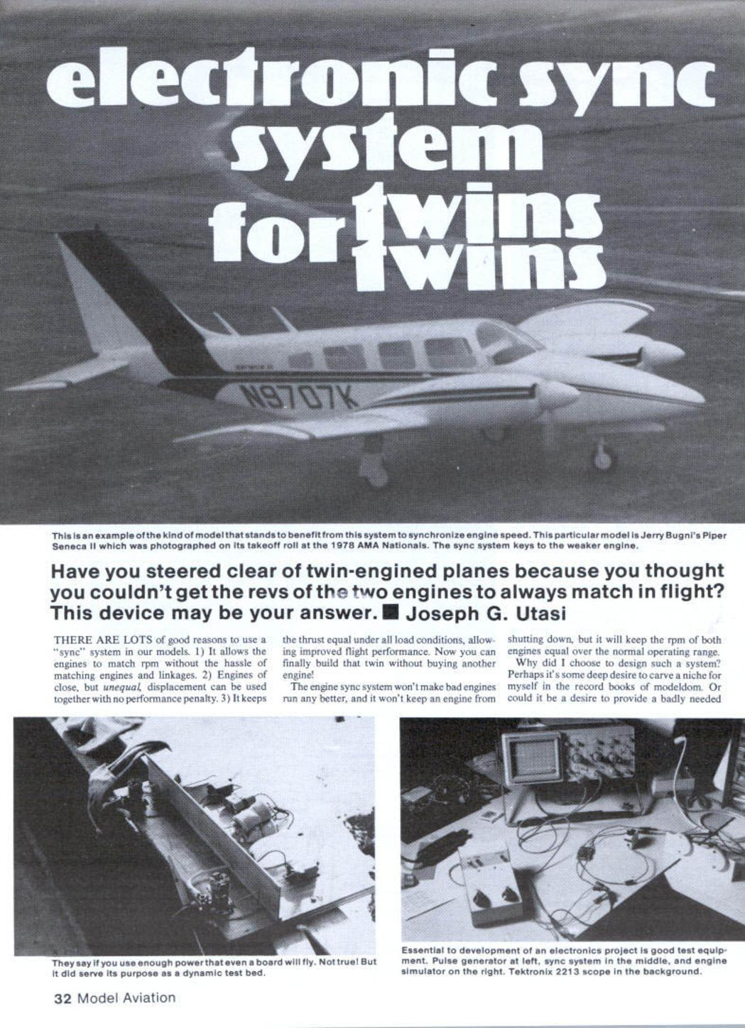
Have you steered clear of twin-engined planes because you thought you couldn't get the revs of the two engines to always match in flight? This device may be your answer.
There are lots of good reasons to use a "sync" system in our models:
- It allows the engines to match rpm without the hassle of matching engines and linkages.
- Engines of close, but unequal, displacement can be used together with no performance penalty.
- It keeps the thrust equal under all load conditions, allowing improved flight performance.
The engine sync system won't make bad engines run any better, and it won't keep an engine from shutting down, but it will keep the rpm of both engines equal over the normal operating range. Now you can finally build that twin without buying another engine!
Why did I choose to design such a system? Maybe it was the nearest thing to a real engineering challenge. Development began the winter of 1979, snowbound in the hills of Cincinnati. Several prototypes were built and tested with minimal success.
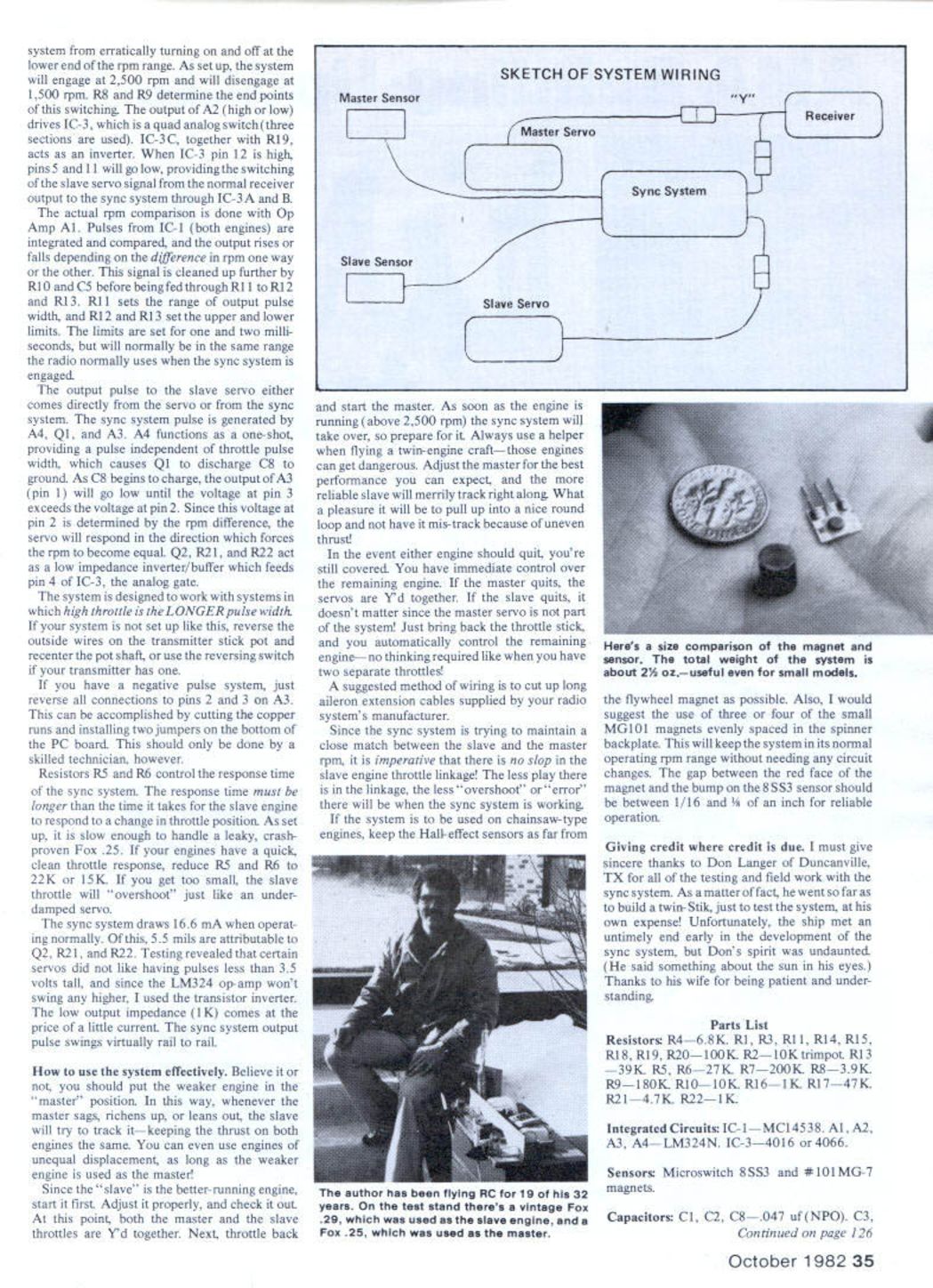
The first engine rpm sensors were a problem. Optical sensing proved unreliable because of variable lighting near the prop hub. Finally, Hall-effect sensors — two small magnets mounted on the rear spinner backplate — did the trick.
The second major problem was how to cleanly sense the master engine running at some minimum speed required to engage the sync system. After some embarrassingly complicated circuitry a simple, effective circuit was settled on. The first approach, a sync detector (a phase-locked-loop sort of obvious solution), appealed to the engineering mentality. After showing it was done on a full-scale twin, the approach came very close to being workable; the slave engine would never settle out to the same rpm, and the master would hunt like a bad servo. It turned out rpm matching does not require the same phase; in other words, both engines do not need to fire at exactly the same instant. A phase-locked loop would tend to correct for changing throttle position and the system could never be satisfied. Back to the drawing board.
After a year of thought, testing, and suggestions from close friend Don Langer, a new circuit design called the differential integrator did the trick — it matched rpm, ignored the phase relationship between engines, and gave better overall sync response: small changes in servo position for small rpm differences, larger changes for larger differences. Also, on initial sync, the slave servo stops moving the exact instant the slave engine rpm matches the master.
Functional description
RPM sensing
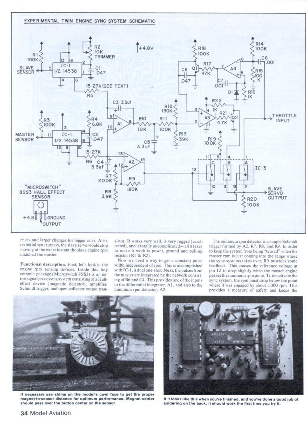
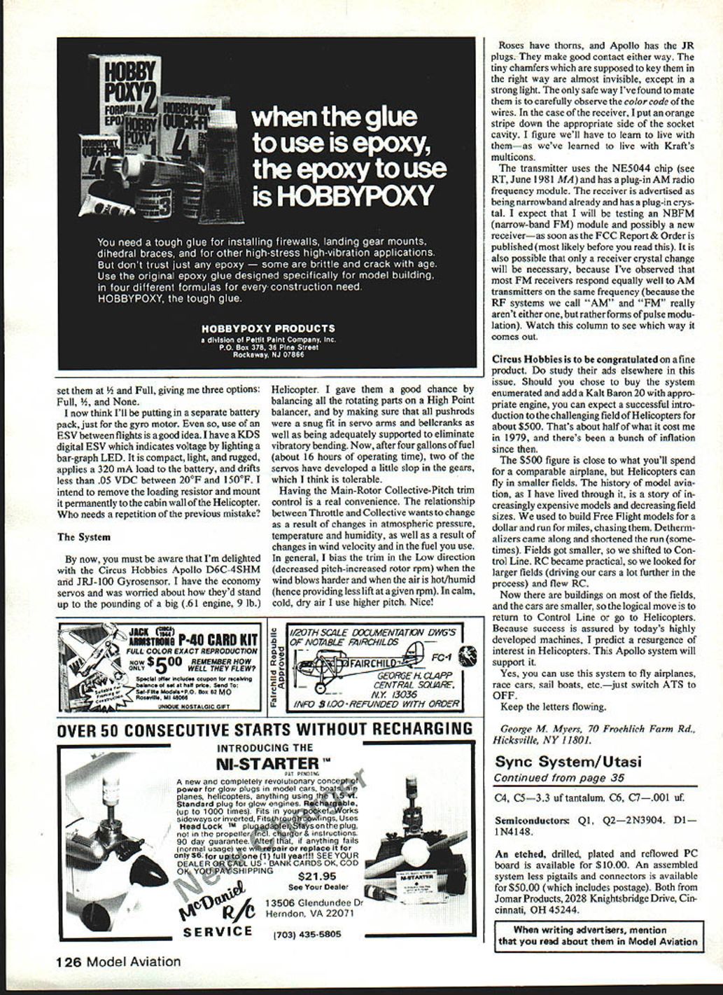
Inside a tiny ceramic package, the Microswitch 8SS3 contains the entire signal processing system — a Hall-effect device, magnetic detector amplifier, Schmitt trigger and open-collector output transistor. It works very well, is rugged, crash tested and uncomplicated. All it takes to make it work is power, ground and a pull-up resistor (R1 & R2).
To get a constant pulse width independent of rpm, pulses from each engine sensor are stretched to a fixed width by IC-1, a dual one-shot. The conditioned pulses are then processed by the differential integrator which produces an error signal proportional to the rpm difference between the two engines.
Minimum RPM detector
The minimum rpm detector is a simple Schmitt trigger formed by A2, R7, R8 and R9. To keep the system from being "teased" when the master rpm is just coming into the range where the sync system takes over, R9 provides feedback. This causes the reference voltage at pin 12 to drop slightly when the master engine passes the minimum rpm point. To deactivate the sync system, the rpm must drop below the engagement point by about 1,000 rpm. This provides a measure of safety and keeps the sync system from hunting when the master throttle is being changed rapidly.
Differential integrator and driver
The differential integrator (A1) compares the master and slave pulse trains and produces an error signal proportional to the rpm difference. The integrator time constants are set by C3 and C5 together with their associated resistors. The A1 output is fed to the driver stage which, through A3, R21, R22 and Q2, operates the microswitch/relay arrangement of IC-3 to provide the slave servo output.
A4 and Q1 provide dynamic response for larger rpm differences while the integrator loop handles small differences. Diode D1 and the associated resistors limit and damp the output to prevent hunting and overshoot.
Output pulse and servo control
The output pulse to the slave servo either comes directly from the transmitter servo output or from the sync system. The sync-system-generated pulse is produced by A4, Q1 and A3. A4 functions as a one-shot, providing a pulse independent of throttle pulse width; this causes Q1 to discharge C8 to ground. As C8 begins to charge, the output of A3 (pin 1) will go low until the voltage at pin 3 exceeds the voltage at pin 2. Since the voltage at pin 2 is determined by the rpm difference, the servo will respond in the direction which forces the rpms to become equal. Q2, R21 and R22 act as a low-impedance inverter/buffer which feeds pin 4 of IC-3, the analog gate.
The system is designed to work with setups where high throttle corresponds to the longer pulse width. If your system is not set up like this, reverse the outside wires on the transmitter stick pot and recenter the pot shaft, or use your transmitter's reversing switch if it has one. If you have a negative-pulse system, reverse the connections to pins 2 and 3 on A3 (this requires cutting copper runs and installing jumpers on the PCB and should only be done by a skilled technician).
Resistors R5 and R6 control the response time of the sync system. The response time must be longer than the time it takes the slave engine to respond to a change in throttle position. As supplied, it is slow enough to handle a leaky, crash-prone Fox .25. If your engines have a quick, clean throttle response, reduce R5 and R6 to 22K or 15K. If made too small, the slave throttle will overshoot, like an under-damped servo.
Power and output characteristics
The sync system draws 16.6 mA during normal operation. Of this, about 5.5 mA is attributable to Q2, R21 and R22. Testing showed certain servos did not like pulses less than 3.5 volts tall, and because the LM324 op amp won't swing any higher, a transistor inverter is used. The low output impedance (≈1K) costs a little current, but the sync-system output pulse swings virtually rail-to-rail.
Operation and usage tips
- Put the weaker engine in the "master" position. When the master sags, richens or leans out, the slave will track it, keeping thrust equal. You can use engines of unequal displacement as long as the weaker engine is the master.
- Start the slave (the better-running engine) first. Adjust it properly; at this point both master and slave throttles are Y'd together.
- Throttle back and start the master. As soon as the master is running above about 2,500 rpm the sync system will take over.
- Always use a helper when flying a twin-engine craft — those engines can be dangerous.
- Adjust the master for the best expected performance; the more reliable slave will then track it.
- If the master quits, the servos are Y'd together so you still have immediate control over the remaining engine. If the slave quits, the master remains under direct control because the master servo is not part of the sync system.
Wiring suggestion: cut up long aileron extension cables supplied by your radio system's manufacturer for pigtails and connector wiring.
Since the sync system maintains a close match between slave and master rpm, ensure there is no slop in the slave engine throttle linkage. Less play means less overshoot or error. For chainsaw-type engines, keep the Hall-effect sensors as far from the flywheel magnet as possible. Consider using three or four small MG101 magnets evenly spaced in the spinner backplate to keep the system in its normal operating rpm range without circuit changes. The gap between the face of the magnet and the bump on the 8SS3 sensor should be between 1/16 and 1/8 inch for reliable operation.
Acknowledgements
Sincere thanks to Don Langer of Duncanville, TX for testing and field work. Don built a twin-Slit to test the system at his own expense; unfortunately the ship was lost early in development. Thanks also to his wife for patience and understanding.
Parts List
- Resistors:
- R4 — 6.8K
- R1, R3, R11, R14, R15, R18, R19, R20 — 100K
- R2 — 10K trimpot
- R13 — 39K
- R5, R6 — 27K
- R7 — 200K
- R8 — 3.9K
- R9 — 180K
- R10 — 10K
- R16 — 1K
- R17 — 47K
- R21 — 4.7K
- R22 — 1K
- Integrated Circuits:
- IC-1 — MC14538 (dual one-shot)
- A1, A2, A3, A4 — LM324N (op amp)
- IC-3 — 4016 or 4066 (analog switch)
- Sensors:
- Microswitch 8SS3 (Hall-effect sensor package)
- MG101 magnets (small)
- Capacitors:
- C1, C2, C8 — 0.047 uF (NPO)
- C3, C4, C5 — 3.3 uF tantalum
- C6, C7 — 0.001 uF
- Semiconductors:
- Q1, Q2 — 2N3904
- D1 — 1N4148
Availability and ordering
An etched, drilled, plated and reflowed PC board is available for $10.00. An assembled system (less pigtails and connectors) is available for $50.00 (includes postage). Both are available from:
Jomar Products 2028 Knightsbridge Drive Cincinnati, OH 45244
When writing advertisers, mention that you read about them in Model Aviation.
Transcribed from original scans by AI. Minor OCR errors may remain.

