
Eloy Marez
Electronics
Welcome to Model Aviation's bimonthly electronics column. Wait — don't go away! While electronics is inherently complicated, the basics are simple and can be explained in common terms.
My main goal is to remove some of the mystery associated with the electronics in modeling and, in so doing, ensure that you get the utmost in efficiency and reliability from your sometimes-expensive equipment.
This will be my column only because I'm the one punching the keys on my word processor. Otherwise, think of it as a meeting place, similar to the flying field, to discuss what works, what doesn't, and to ask questions.
I don't claim to know it all, and I will never have enough time to try everything, but I have many sources and can probably come up with whatever information is needed. All mail will be answered directly (SASE please), although letters of general interest will be included in future columns.
My qualifications? AMA member number 1995—an original issue! I got my first RC (radio control) airplane (Mac's Robot) in 1953 or 1954. Now I'm limited to sport flying, but I'm a real builder—cut, glue, shape, sand, cover, paint, etc.
I was also an electronics columnist for Model Builder for about 15 years.
I retired from the US Air Force after 24 years as a flight radio operator, with Ham licenses in a number of countries. I have worked in the RC industry since the early days, from being a technician up to flying the LSD (USAF nomenclature for Large Steel Desk).
Costs
In my discussions with RC fliers around the country, I often hear gripes about how expensive the hobby is—especially the radio equipment.
My first commercially made radio cost $700 in the late 1960s. When you can buy a five-channel computer system with all commonly required mixers, a double-conversion narrow-band receiver, four excellent servos, and name-brand Ni-Cd batteries and a charger, all assembled using the latest surface-mount technology, for around $200, you shouldn't complain.
Surface-Mount Technology (SMT)
Electronic equipment construction methods have changed drastically in recent years. As more reliable and faster assembly methods were developed, SMT was adopted by the RC industry.
RC for the masses really started with the development of the transistor and received a major boost when the integrated circuit (IC) came along: dedicated circuitry containing sometimes hundreds of transistors and related components in a device no larger than a match head.
The IC, as we know it, is packaged to allow handling and to simplify required connections. In the earliest days, everything was built using older leaded components.
ICs made smaller, lighter, more reliable equipment possible, but they—along with related components—required a mounting surface called a printed circuit (PC) board, in which very small holes had to be accurately drilled to accept the wire leads.
Enter SMT. All components, including the valuable ICs, no longer have long leads; they have small "feet" that are soldered to pads on the PC board. Equally important, everything shrunk—in most cases to less than half the size of older leaded components—and the weight went down significantly.
Some components designed for SMT assembly are referred to as surface-mount devices (SMDs). All assembly, and in some cases even testing, is done by robotic equipment, eliminating those Monday-morning assembly problems of the past.
Servos
My theory is that people like to discuss servos because they are the only part of the system that has any life; we can see movement! The rest of the RC system is part of that mystery I mentioned earlier.
Servos come with a rubber grommet and a brass eyelet, through which they are screwed down to a servo tray or wooden mounts. More often than not, instructions are not clear, or they're ignored, and the eyelets are installed from the top; they should go from the bottom, up.
If installed from the top, the sharp bottom edge of the eyelet will dig into whatever it is screwed to—especially wood. The screw can be tightened so much that the grommet is squeezed past the point at which it can provide the vibration isolation it was intended to provide. As with all electronic equipment, servos prefer not to work under vibration.
The wide lip on the eyelet installed from the bottom prevents it from digging into the mount and actually limits the amount the grommet can be compressed.
The screws used to mount servos are critical to some degree. I don't like to use wood screws or sheet-metal screws because of Murphy's Law: if something can go wrong, it will. They can and do vibrate loose (so check yours), especially if you remove the servos for any reason; the more times the screw goes in and out, the looser it becomes. I prefer threaded holes; a #3-48 machine screw is a perfect fit in brass eyelets. By threading the holes in the plastic or wooden mount, vibration will not get to the screws; you can remove the servos all you want without them being loose when reinstalled.
When threading into wood, do the following:
- Thread the hole once.
- Run a drop of thin CYA (cyanoacrylate) into the hole and let it dry thoroughly.
- Run the tap through once again.
This gives you a hardened thread that will last almost as long as one in plastic.
The #3 is the proper type of screw, no matter what type of screw you use. The #2 is too small. It may not be significant to most of us, but to those who claim they need a voltage regulator for their five-cell packs because they can tell the difference in servo operation if the voltage drops two hundredths of a volt, the .013-inch slop that results from using No. 2 screws must be unacceptable!
Getting the screw holes in the proper place is important. It's not a problem if you use the predrilled plastic mounts, but it can be if you use wood. You might have seen the ads for Great Planes' Dead Center Engine Mount Hole Locator (DCEMHL); I got mine two airplanes ago, and it is the best $8.99 I have spent in a long time.
The DCEMHL does a perfect job of locating the holes in the engine mount and in much less time than the "measure twice, drill once" method that I had evolved.
The DCEMHL also does a perfect job of locating the mounting holes for servos. Just be sure that the grommets are inserted properly, temporarily insert the eyelets from the top, and use the DCEMHL (as instructed) to locate the holes. Drill and tap the holes, and the servos will mount without any distortion or pulling of the grommets. Don't forget to reinstall the eyelets from the bottom.
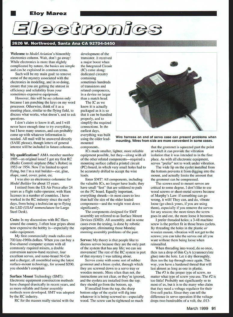
If you have ever mounted servos any way other than in the plastic trays, you might know that the wire sticking out of one end can be a problem; you have to make some sort of groove or cutout for it to clear, which sometimes weakens the mounting structure.
Attention, radio manufacturers: it would help if that wire came out of the side. In some cases, you can make it.
I can't check all servos to see if the wire can be made to come out of the side, but all it takes in some servos is cutting a slot in the side of the case (and maybe the bottom) similar to the slot(s) in the end, and rerouting the wire.
There are some maybes. Some servos have the wires attached on the bottom of the PC board, and others have them on top. Some—especially the miniservos and microservos—probably have no room for the wire other than the path originally created for it. The standard-size servos I tried (Airtronics 102 & 322, Futaba 148, Hitec 300, Tower TS-3) were easily changed.
A caution with the Futaba 148 (and possibly other models): the PC board is a combination of through-hole and SMT; it has many point and wire ends sticking up from the board in the area where you might want to reroute the wiring. Trim the wire points flush with the board. Otherwise, the pressure of the bottom cover might cause one of the ends to puncture the wire's insulation, with disastrous results. Inserting a piece of thin acetate sheet under the wires is desirable.
Till next time, 73 (best regards), as we Hams say. Remember that you have input regarding the direction this column will take; write and let me know.
Transcribed from original scans by AI. Minor OCR errors may remain.

