
Electronics
Eloy Marez
The mail has started to come in; thanks to all who wrote, welcoming me to Model Aviation and offering their best wishes!
Other mail — just as welcome — arrived with questions, such as from Edward O. Clark III, Columbia, SC:
"I have two transmitters (Futaba FP-T4NBF): 1) channel 50, damaged beyond repair; 2) channel 36, operable. Can I take the crystal from #50 and use it in the operable transmitter (#36) safely? I have done this on the bench, and it seems to work OK, but I have had varying advice on this issue."
I have heard this question often, and I don't remember ever seeing it answered in an instruction manual, for a very good reason: Federal Communications Commission (FCC) regulations specifically prohibit changing crystals in radio-control (RC) transmitters.
Then why are the crystals so easily accessible in many transmitters, and plugged into a socket rather than soldered? My guess is that the same transmitters are being made for sale in countries without such restrictions; some countries have no regulations for RC equipment.
The reasoning is that without proper testing and tuning, the transmitter can operate in such a manner that will cause interference on frequencies other than the intended one. RC companies handle this situation in different ways; some make crystals readily available, while others provide them only to qualified service centers.
While on the subject of FCC regulations, the Type Approval label on the back of the transmitter indicates that it meets all pertinent FCC restrictions and specifications after testing by certified independent laboratories. The Type Approval is granted to the equipment on the installed frequency and with the furnished antenna. Said specifications include many things, including all-important narrowband emission limits for the transmitter. The receiver is subject to a different set of regulations and comes with its own sticker. The receiver's restriction is that it must not radiate radio-frequency energy that might interfere with other electronic devices.
Your television bears a similar sticker, as does your telephone and even your microwave. There are no restrictions for changing crystals in the receiver, and the narrowband restrictions on receivers are AMA- rather than FCC-imposed.
Furthermore, the "double conversion" you may hear about is not an FCC restriction—it's circuitry required in some cases to meet AMA narrowband requirements.
The reason why equipment is pre‑tuned to a specific frequency is efficiency: maximum radio-frequency output from the transmitter and maximum sensitivity from the receiver. Circuitry that would operate equally well on all channels would result in increased size and weight that most of you would not accept.
In the real world, if crystals are available — and they are — system frequencies are going to be changed, so do it safely. When it comes to any radio maintenance, consider the cost of your airplane in money, time, or both; then factor in the cost of having your radio properly serviced.
Because Airtronics is within my area code I can call with no extra telephone charges. I use that company as a source more than I use others. In this case I was told that a frequency change, including new crystals, is $35. It is worth that to me not to sweat out the first flight after plugging in a different set of crystals. Even my oldest airplane is worth more than that.
However, there are cases with extenuating circumstances, such as Ed Clark's. If he did not already have the crystals, I would advise him of the rule of thumb, more or less: stay within five channels, up or down, of the original frequency.
Since Ed has a set of crystals to try, there is a good go/no-go test, which is actually good advice in all cases—even if you are only changing one channel away.
- With the equipment on the original frequency, and preferably out of the airplane (place the airplane on a large cardboard box, wooden stool, or similar nonmetallic object) and with the antenna upright on a wooden stick, establish an antenna-down operating range.
- After changing the crystals, make a comparison test. If you lose more than 10% range, do not fly it without first having it properly checked and tuned.
Second, even with equal range, don't put the system into that B-17 that took you three years to build. Test it in a more expendable airplane.
There is also a worthwhile airborne range test that you can make, which is a good idea even if you haven't changed channels. With the airplane overhead—as high as you can have it and still see it well—collapse the transmitter antenna one section at a time. With most good-quality, properly tuned systems, you should be able to maintain control with only one antenna section extended. If you lose it at, say, half-antenna, you really should have it checked out. Though it will probably work acceptably with a full antenna, it will let you down sometime on a long approach—especially if you are in the habit of pointing the antenna at the airplane.
Bill Robinson of Gainesville, Florida, posed an interesting question:
"I would like to Y two servos together (A + B). I would like servo B to operate when servo A is in a particular position, triggered by a momentary switch. I only need servo B to activate one way at that time. Logic would say you could interrupt a signal to B by the momentary switch, but which wire controls B activity? Also, is there any problem with feedback or battery drain when B is deactivated? Are there any other ways to accomplish this process other than a dedicated channel?"
It would be interesting to know what Bill's application is; maybe he will let us know when he reports back, if my suggestion works for him.
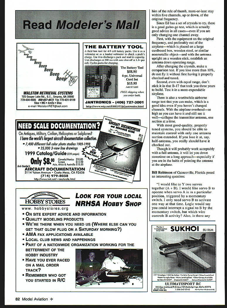
A review of why those three servo wires are there: two wires provide battery power (positive and negative). The third wire carries the control information from the receiver, telling the servo when to move and when to stop. Unfortunately, there is no universal standardization of pin sequence or wire colors.
In Bill's case, the wire to be switched in and out is the battery negative. It might seem more obvious to switch the control signal, but with some servos in some systems, overshoot can occur. Switching the battery negative stops the servo instantly.
However, there is a downside to this method: the servo must have battery power to develop holding force. You can easily move a control surface when the radio is off, but not so when it is on. If whatever the servo is being used to actuate will push back, it can shift the servo position, though in low-torque applications it will be okay.
Other ways? Depending on the application, some of the computer radios with compensation mixing might fit the bill. In most cases, you can designate any channel as a master and any other as a slave, then adjust the slave to operate only to one side of the master stick movement with only the desired degree. With the proper mechanical linkage, what I think Bill is attempting to do could be accomplished. Bill, let me know what works for you so I can share it; others might find it useful.
Hint of the Month
This one has to do with those unused channels on your RC transmitter. The exposed male pins are carrying that battery voltage I was just writing about. If anything conductive (such as that screw you dropped in the fuselage while installing the servos) gets across them, there will be fireworks. It is a good idea to put a piece of tape over all unused connectors.
Another Suggestion
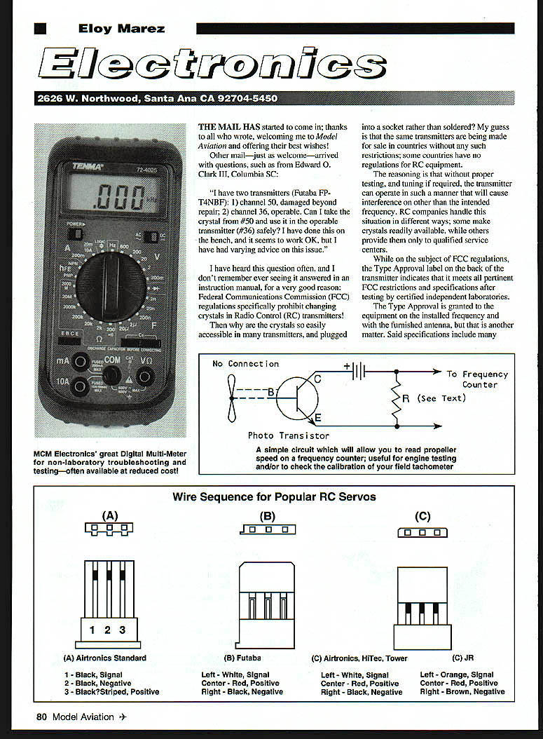
A great buy for the basic tinkerer is a Digital Multi‑Meter (DMM). MCM Electronics (800-543-4330) in Ohio offers a wide range of electronic components and products, including test equipment. MCM catalogs a Model 72-4025 DMM with a 3 1/2-digit, 1/2-inch-high display that is ideal for all tests not requiring laboratory precision. That includes voltage and current (AC and DC), resistance, capacitance to 20 µF, transistors and diodes, and even frequency to 20 MHz. It comes with a one-year warranty.
The 72-4025 DMM is normally priced at $65.95. However, MCM has had periodic specials on it for about half price, and you can't do better than that, no matter how much you shop around. If you are in the market for a good instrument, give MCM a try. Ask if the special price is currently in effect, or when it will be.
Other catalogs that tinkerers should have:
- Digi-Key (800-344-4539), Minnesota
- Mouser Electronics (800-346-6873), with facilities in California, New Jersey and Texas
- Tech America (800-877-0072), Texas
More Test Equipment
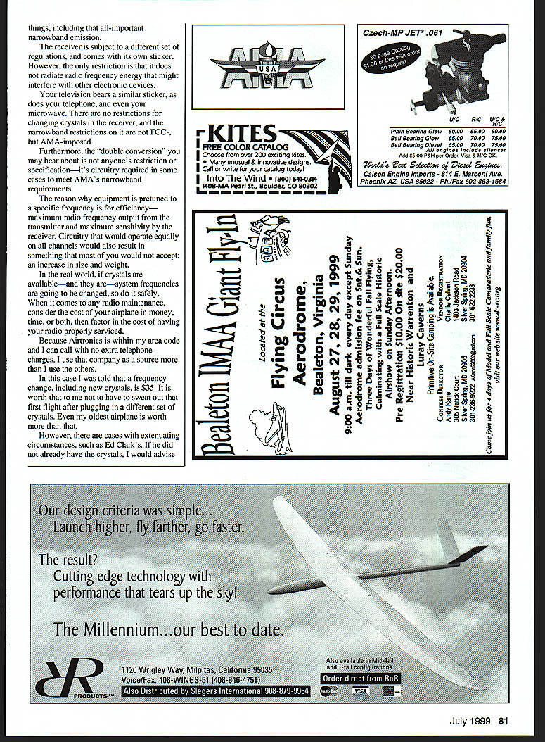
If you own or have access to a frequency counter, you can use it with a simple adapter as a digital tachometer—to check the accuracy of, or to calibrate, an existing tachometer. There is nothing critical about the circuit. Almost any NPN phototransistor will work; I have used the NTE3001, primarily because it is readily available.
The value of the resistor is determined by the input impedance of the counter in use; start with 47K and work up or down until the reading stabilizes. The actual rpm is the indicated frequency in hertz, divided by the number of propeller blades, multiplied by 60.
Your questions and/or input are welcome, but please enclose an SASE if you want a direct answer.
Transcribed from original scans by AI. Minor OCR errors may remain.

