

Electronics
Eloy Marez
2626 W. Northwood, Santa Ana, CA 92704
WHERE ARE the kids? Pardon me while I deviate from the intended theme, but this is a subject we read about often—not only in the pages of MA, but in the rest of the model press.
Wherever the kids may be, few of them are out at the model fields in the United States. However, they are a common sight at Latin American fields!
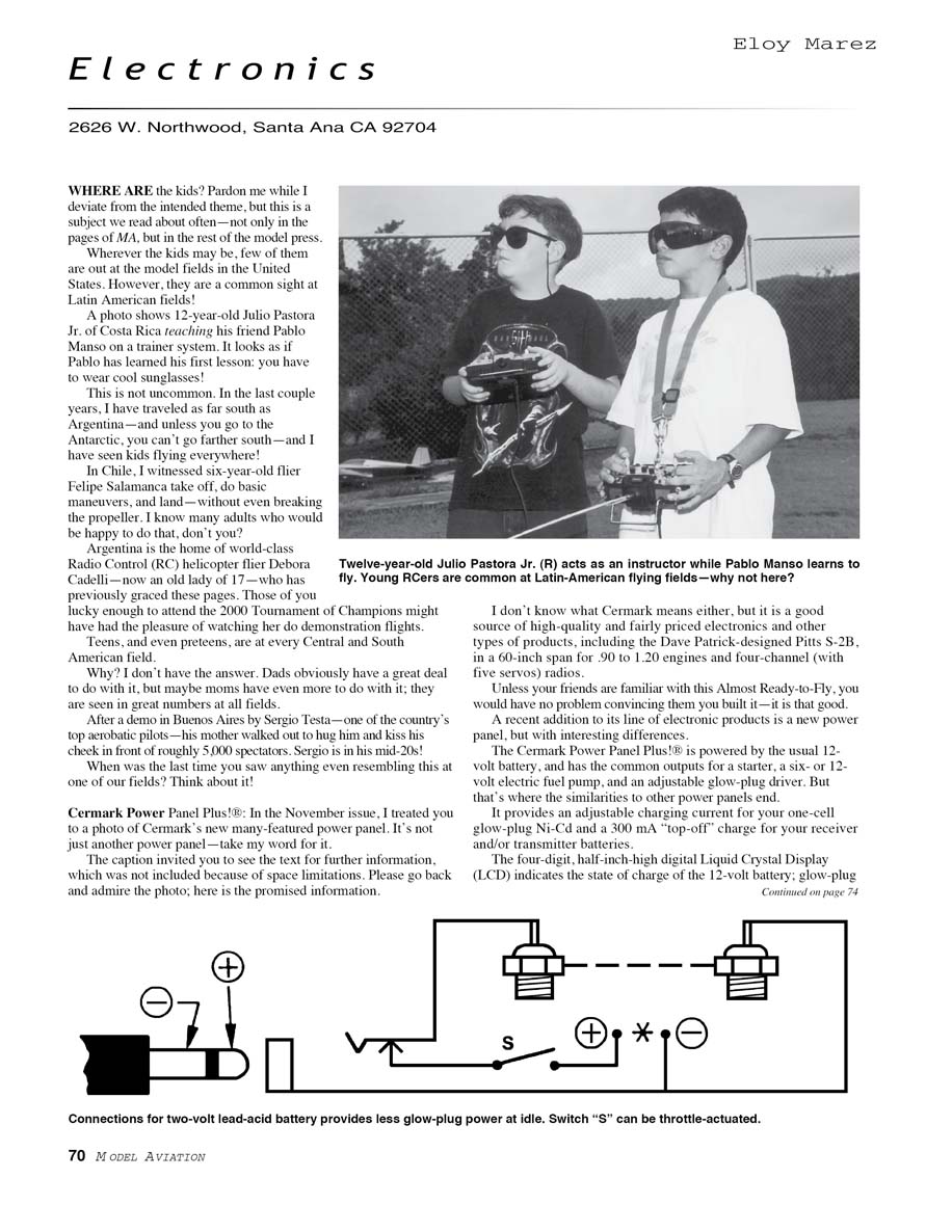
A photo shows 12-year-old Julio Pastora Jr. of Costa Rica teaching his friend Pablo Manso on a trainer system. It looks as if Pablo has learned his first lesson: you have to wear cool sunglasses!
This is not uncommon. In the last couple years, I have traveled as far south as Argentina—and unless you go to the Antarctic, you can’t go farther south—and I have seen kids flying everywhere!
In Chile, I witnessed six-year-old flier Felipe Salamanca take off, do basic maneuvers, and land—without even breaking the propeller. I know many adults who would be happy to do that, don’t you?
Argentina is the home of world-class radio control (RC) helicopter flier Debora Cadelli—now an "old lady" of 17—who has previously graced these pages. Those of you lucky enough to attend the 2000 Tournament of Champions might have had the pleasure of watching her do demonstration flights.
Teens, and even preteens, are at every Central and South American field.
Why? I don’t have the answer. Dads obviously have a great deal to do with it, but maybe moms have even more to do with it; they are seen in great numbers at all fields.
After a demo in Buenos Aires by Sergio Testa—one of the country’s top aerobatic pilots—his mother walked out to hug him and kiss his cheek in front of roughly 5,000 spectators. Sergio is in his mid-20s!
When was the last time you saw anything even resembling this at one of our fields? Think about it!
Cermark Power Panel Plus!®
In the November issue, I treated you to a photo of Cermark’s new many-featured power panel. It’s not just another power panel—take my word for it.
The caption invited you to see the text for further information, which was not included because of space limitations. Please go back and admire the photo; here is the promised information.
I don’t know what "Cermark" means either, but it is a good source of high-quality and fairly priced electronics and other products, including the Dave Patrick-designed Pitts S-2B, in a 60-inch span for .90 to 1.20 engines and four-channel (with five servos) radios.
Unless your friends are familiar with this Almost Ready-to-Fly, you would have no problem convincing them you built it—it is that good.
A recent addition to its line of electronic products is a new power panel, but with interesting differences.
The Cermark Power Panel Plus!® is powered by the usual 12-volt battery, and has the common outputs for a starter, a six- or 12-volt electric fuel pump, and an adjustable glow-plug driver. But that’s where the similarities to other power panels end.
It provides an adjustable charging current for your one-cell glow-plug Ni-Cd and a 300 mA “top-off” charge for your receiver and/or transmitter batteries.
The four-digit, half-inch-high digital liquid crystal display (LCD) indicates the state of charge of the 12-volt battery; glow-plug driver current; receiver battery voltage under a 300-milliamp load; transmitter battery voltage under a 300-milliamp load; and glow-plug Ni-Cd charging current. This is the power panel to replace all power panels, and it carries a $59.95 MSRP (Manufacturer’s Suggested Retail Price). Check your favorite dealer for the current “street” price.
Contact Cermark:
- 107 Edward Ave., Fullerton, CA 92833
- Tel.: (714) 680-5888
- Fax: (714) 680-5880
- E-mail: Cermark@aol.com
Expanded Scale Voltmeters
Another misnomer has found its way into our RC vocabulary. Manufacturer's and editorial copy often refer to digital voltmeters, as in the Cermark Power Panel, as Expanded Scale Voltmeters (ESVs) when they are used to read battery voltage.
That is not correct. The term ESV appeared when the only test meters we had were analog types; i.e., scale-and-needle indicator devices. When connected to read voltage, such instruments normally read zero to something—say, 1–10 volts.
That does not provide much accuracy on a two-inch-long scale—little more than a quarter of a volt.
However, when testing, say, a 4.8-volt receiver, values much below and above that amount are of no interest, so the reading was "expanded" to read only four to six volts.
With any applied voltage less than four volts, the needle did not move off the left side—or originally, the zero point. It would start to move at four volts, reaching its right-side extreme of travel at six volts.
Reading only two volts instead of 10 on the two-inch-long scale made it possible for a far greater degree of accuracy.
The digital voltmeter is of a different breed; a 0- to 10-volt-reading instrument can automatically come with far greater accuracy—often down to the hundredths of a volt. It does not require "expanding," or reducing its range, in any manner. It could be done, but without an increase in its accuracy.
For RC use, both types of instruments are often designed to "load" the battery—that is, draw a certain amount from it while it is being tested. That seems to be where the wordsmiths go wrong; any voltage-reading meter that loads the battery being tested, regardless of whether the display is analog or digital, becomes an "Expanded" Scale Voltmeter.
Servo Screws and the Proper Mounting of Servos
As with all components of RC systems, servos and servo screws have been greatly improved from what we lived with in the early days of EK, Kraft, and Orbit!
In the phrase "fantastic power and resolution," the last word—resolution—is the term used to describe how accurately and repeatedly servos follow your commands. Unfortunately, some of that precision is lost through sloppy installations.
First, those metal grommets that all manufacturers provide need to be installed from the bottom—not from the top, as is often seen. The reason is that when installed with the sharp edges down, they will dig into the mounting material—especially if plastic trays are not used and the servo is being mounted on wood.
The results are too much compression of the rubber grommet, eliminating most of its shock and vibration isolation. When the brass grommet is installed correctly, from the bottom (large side upward), the base will not dig into the mounting surface and the rubber grommet is not overly compressed.
Next, select the proper mounting screws. Servo-makers generally furnish sheet-metal or wood screws for mounting servos. They will work, but they are the easy way out—and the easy way is not necessarily the most efficient way.
My opinion (backed up with years and hundreds of in-flight hours without a single servo coming loose) is to use machine screws in threaded wooden beam mounts. It is slightly more work, but the sense of security is well worth it.
Equally important is using the proper-size screw—regardless of the type you prefer. I see many servos mounted with No. 2 hardware; that is far too small for the hole in the bronze grommet, allowing enough shift when the servo is under load to lose all that precision you paid for in the first place.
Most grommets are better fits for No. 3 or No. 4 screws; use the one that fits closest with the grommets in use.
Marking and drilling the holes properly is important, and I have found a surefire method to do it.
- Install those brass grommets correctly—with the large side upward.
- With the servo locked in position, mark the mounting holes with one of Great Planes' Engine Mount Hole Locators. The name indicates its primary intended use, but it is the perfect tool for locating mounting holes for anything requiring already-located mounting holes.
- Drill the proper-size hole for the final tap size, tap once, and drop some thin cyanoacrylate glue into the hole.
- Let the adhesive dry thoroughly, then re-tap it.
The result will be a perfect thread that will accept installation and removal of the servo as many times as you want to do so, without losing security.
Lighting Glow Plugs at Idle
This is not a new concept, but I have a different approach for those of you running twin-cylinder engines.
Once the engine is running, you don't need full voltage on the plug to keep the engine going during long periods of idle. Full voltage, as applied during the starting process, cannot damage the engine, but it has to overheat the plug and shorten its life if applied for long periods of time.
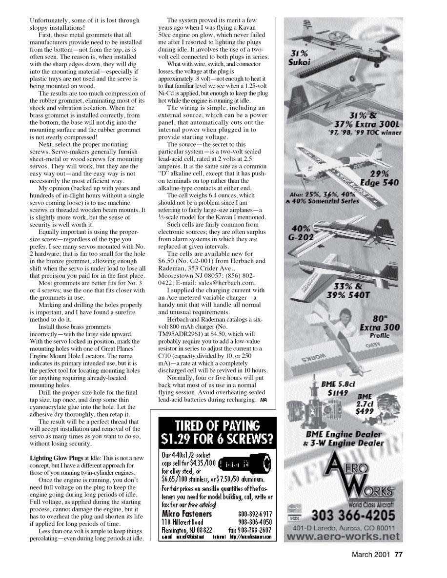
Less than one volt is ample to keep things percolating—even during long periods at idle.
The system proved its merit a few years ago when I was flying a Kavan 50cc engine on glow, which never failed me after I resorted to lighting the plugs during idle. It involves the use of a two-volt cell connected to both plugs in series.
What with wire, switch, and connector losses, the voltage at the plugs is approximately 1.8 volts—not enough to heat it to that familiar level we see when a 1.25-volt Ni-Cd is applied, but enough to keep the plug hot while the engine is running at idle.
The wiring is simple, including an external source, which can be a power panel, that automatically cuts out the internal power when plugged in to provide starting voltage.
The source—the secret to this particular system—is a two-volt sealed lead-acid cell, rated at 2 volts at 2.5 ampere-hours. It is the same size as a common "D" alkaline cell, except that it has push-on terminals on top rather than the alkaline-type contacts at either end.
The cell weighs 6.4 ounces, which should not be a problem since I am referring to fairly large-size airplanes—a 1/3-scale model for the Kavan I mentioned.
Such cells are fairly common from electronic sources; they are often surplus from alarm systems in which they are replaced at given intervals.
The cells are available new for $6.50 (No. G2-001) from Herbach and Rademan:
- Herbach and Rademan, 353 Crider Ave., Moorestown, NJ 08057
- Tel.: (856) 802-0422
- E-mail: sales@herbach.com
I supplied the charging current with an Ace metered variable charger—a handy unit that will handle all normal and unusual requirements.
Herbach and Rademan catalog a six-volt 800 mA charger (No. TM95ADR2961) at $4.50, which will probably require you to add a low-value resistor in series to adjust the current to a C/10 (capacity divided by 10, or 250 mA)—a rate at which a completely discharged cell will be revived in 10 hours.
Normally, four or five hours will put back what most of us use in a normal flying session. Avoid overheating sealed lead-acid batteries during recharging.
MA
Transcribed from original scans by AI. Minor OCR errors may remain.

