
Electronics
Eloy Marez 2626 W. Northwood, Santa Ana CA 92704
TRICKLE-CHARGING is a somewhat controversial subject in the model press and at the flying field. Being a firm believer in going to the established experts on a particular subject, I did exactly that.
Knowing that the real experts are not the guy with his Mach 3 turbine airplane or the one with the 1/2-scale Extra that flies all those impossible maneuvers, I researched the nickel cadmium (Ni-Cd) battery manufacturers' literature. Following is some of what I learned.
Sanyo Electric Co., Ltd., probably the best known Ni-Cd battery supplier to the Radio Control (RC) hobby, states in its Engineering Handbook that, "In trickle charge, the battery is continuously charged at a very low rate, from C/50 to C/20, and is kept fully charged and ready for use."
Let's review C/X. The rated capacity of an Ni-Cd cell, or battery, is indicated as "C" and stated in milliampere-hours (mAh). This is the maker's rating, usually printed on the battery covering, and is generally thought to be the current in milliamperes that the cell will produce in a one-hour period.
That is not so; it is the accumulative current at a lower rate during a period varying with different manufacturers from two to five hours to a cutoff voltage—usually 1.0 or 1.1 volts per cell.
Sanyo's cells are rated "at a 5 hour rate at 0.2C discharge current." (The text uses C/X in some cases and .XC in others—a different way of saying the same thing.) Sanyo's method of rating its cells for capacity is to load a cell to 0.2C for five hours; the results are the published rating. A 600 mAh cell is tested at 120 milliamps and should provide that current for five hours. With Sanyo's recommended trickle rate being C/50 to C/20, the rate for a 600 mAh battery would be 12–30 milliamps.
Saft America Inc., the battery manufacturer that owns the term "Nicad" (often applied erroneously to cells by any maker), states, "Trickle charge—a charging technique which maintains full capacity in a cell or battery, normally at a C/20 or C/30 rate." That would be 20–30 milliamps for the 600 mAh battery. Saft also rates its cells at the 0.2C rate.
Power-Sonic Corporation, another Ni-Cd battery maker, states: "Trickle charge: In this charge method, charging is continuous at a low rate—typically at C/20 to C/50—to compensate for self-discharge and to keep the battery in a fully charged state." Power-Sonic also rates its batteries at the five-hour 0.2C rate.
Trickle-charging is a recommended procedure—not by that hotshot flier at the field, but by the real experts who produce these batteries.
What is the best way to accomplish the task? There are two basic possibilities:
- Reduce the AC input to the charger.
- Reduce the DC output from the charger to the battery.
The first method can be accomplished with a number of commercially available devices, such as the Multi-Trickler described in the January column. There is also an Auto-Trickle Adapter available from TME (Box 340608, Tampa FL 33694; Tel.: [813] 968-9510).
Several accessory chargers available within the RC airplane market, such as ones from Ace R/C, automatically switch to a trickle rate after the higher full-charge rate is completed. The trickle current is usually published and should be checked for compatibility with the battery in use.
I refer to the "RC airplane market" because in some cases electric power fliers are adopting chargers primarily intended for RC cars. Those manufacturers have reinvented the wheel when it comes to ratings; they have gone outside the normal parameters established within the electronics industry or the RC airplane hobby. Check the ads for RC car electronic speed controls. You will see current ratings for amperage only possible with a direct connection to Grand Coulee Dam—not from Ni-Cd packs currently available.
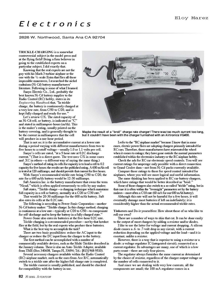
Compare those ratings to those for speed controls intended for airplanes, where you will see more logical and useful information. The same thinking has been applied to RC car-battery chargers, which have ratings that would be better described as "broil."
Some of those chargers also switch to a so-called "trickle" rating, but in that case it is often within the "overnight" parameters set by the battery makers—most often at a C/10 rate (60 mA for a 600 mAh battery). Although this rate will not be harmful for a few hours, it will eventually damage most batteries if left on indefinitely; it is considerably higher than the actual recommended trickle rates.
Tinkerers and Do-it-yourselfers
There are a number of ways to skin that cat. It can be done easily at the output of most chargers by adding a resistor and/or diodes.
I like to use the latter for voltage and current dropping. A silicon diode causes a 0.6–0.7 volt drop in any circuit, with a current reduction depending on the applied voltage and the load—and it is more constant than a resistor.
However, there is a way that is superior to using a resistor or a diode: a voltage regulator IC, connected as a current regulator. Its advantages are many; one is a low parts count—there are only four pieces. The regulator always furnishes the same current as determined by the choice of resistor, regardless of the charger output voltage or the number of cells connected to it.
And since we are dealing with very low currents, all the components are small: the 100 mA regulator comes in a transistor-size package (TO-92), the resistor can be a small 1/4-watt, and the light-emitting diode (LED) can be the smallest available size (T1). All the parts are readily available.
Although the regulator is not a Radio Shack item, it is available from electronics suppliers by its basic nomenclature or as an NTE replacement, No. 1900. There is a Radio Shack part that can be used: No. 276-1778—an LM317T with a larger current capacity and larger (TO-220) package.
The regulator can be assembled in a small plastic box, with no consideration to heat—there is not a significant amount generated. One could equip the regulator with input and output plugs and plug it in after the normal charging cycle, or it could be permanently wired in with a switch to go from normal to trickle. To save a buck or two, a dual unit could be built into the same box to handle the transmitter and receiver batteries.
Even the decisions are easy on this one! Determine the trickle current you want. I have settled for C/30 as an average between those recommended. That comes out to 20 milliamps for a 600 mAh pack.
To determine the value of the one resistor required, use the formula: R (resistance) = 1.25 / I (current in amperes).
Remember that one amp is 1,000 milliamps, so 20 milliamps is 0.020 A. Working out the formula, we determine that a 62.5-ohm resistor is required. Use the nearest available standard value resistor, i.e., 62.0 ohms. The nearest Radio Shack resistor value available, a 68-ohm 1/2-watt unit, will result in an 18 milliamp rate—well within the recommended values.
To check everything, including how good your batteries are, check the battery capacity, recharge, let it trickle for at least a couple of weeks, then check the capacity again. It should be very close to the original figure.
Receiver Talk
Receivers are probably not as confusing to us, because they are smaller and without all those mechanical add-ons that come on transmitters. They get installed, connected, and they work—or not!
Yet receivers still hold some mystery. I was recently asked if a so-and-so receiver was "Gold Labeled," referring to the label that used to be affixed to transmitters to indicate that they were narrowband units.
Let's discuss some common, or not-so-common, somewhat confusing RC receiver terminology we may encounter.
Receivers are not subject to the same federal narrowbanding requirements as transmitters are. There is a Federal Communications Commission (FCC) label on the receiver, but it indicates that the receiver will not emit a radio signal past a designated level. The narrowband requirement is imposed on us by AMA, and it is absolutely necessary for us to be able to use all our assigned frequencies without shooting each other down. It is a good rule, which should be enforced by all contest and club field officials.
If you decide to ignore it and insist on using that antique you've had since the 1960s, you only have yourself to blame when you find yourself yelling, "I ain't got it!"
Some of the terms we use and hear commonly, such as "frequency" and "conversion—single and double," are as definite as "prop pitch" and "wingspan." Others, such as "narrowband," are not. Specific measurements can be made to determine whether or not a receiver's performance fits the AMA-established criteria, but they are highly technical and require specialized equipment and experience to obtain.
As applied to our use, "narrowband" implies that the receiver's window of reception is narrower than older equipment now referred to as "wideband." The AMA Membership Manual includes a simple go-no-go test you can take to determine the merit of a particular receiver.
Conversion, single and double, refers to the conversion of the original operating frequency—the companion transmitter frequency—to a standard one known as the intermediate frequency (IF), at which all the signal processing is done.
In a single-conversion receiver, the operating frequency is converted in one step to 455 kilohertz (kHz)—the standard IF of all RC receivers and most consumer home equipment. The same 455 kHz is reached in a double-conversion unit, but two steps of conversion are used to get there.
The results are that the double-conversion receiver is less susceptible to some types of interference we might encounter in our flying efforts, and it is easier to make narrowband. It can be done with single-conversion units, but more adequate signal filtering has to be done using ceramic and/or crystal filters to achieve the same results.
Up to now we have been dealing with common electronic and receiver technology and terminology. Remember that the world in general uses many more receivers in one form or another than we RCers do, and much of our technology comes from there. We are actually somewhat behind; many high-quality communications receivers, such as the AMA-provided Icom R7000 frequency monitor, are triple-conversion.
I have only skimmed the surface because I wanted to discuss some of the nonstandard terminology we encounter that can make an already complicated subject even worse.
JR claims that its receivers, all of which are basically single-conversion types, are "ABC&W." These receivers work well under current narrowband requirements, and they are mechanically well made. I have no actual figures, but they seem to be the system of choice for the radio-critical serious helicopter fliers—at least those in my area.
ABC&W is not a receiver-oriented term; it is not found anywhere but in JR literature. And even that is confusing; earlier it was described as "Automatic Blocking Circuit and Window," and now it is described as "Anti-Blocking Cross-Modulation and Window."
I have never seen a technical description of what this is, although JR describes it as, "...a very small electronic window. Any signal that is distorted or off-frequency won't fit through the window, and is immediately rejected. Then the new signal is cleaned up, amplified, and sent through the window again." The results are described as "unwanted interference limiting and a higher degree of signal filtration." That's not exactly the circuit-analysis type of explanation I would like to see, but it's what we get.
Whatever ABC&W is, JR receivers work very well indeed.
Another confusing term is "IPD," from the German RC manufacturer Multiplex. Although not all that well known in the U.S., Multiplex is an extremely popular, though expensive, brand in Europe, and is often ahead in design and technical developments. Regardless of what you may have read lately, Multiplex was the first to market a "digital" servo.
A feature of the Multiplex FM receivers, IPD stands for "Intelligent Pulse Decoding." As with the aforementioned terminology, it is not common in the receiver world. Multiplex describes it as "a (micro-)processor which analyses the incoming signal for validity. As does a PCM system, IPD filters out invalid signals."
IPD is reported as being:
- As fast as PPM (pulse-position modulation).
- Compatible with other (non-Multiplex) transmitters.
- Detects invalid signals.
- No servo jitter with transmitter switched off.
- Hold function.
- No servo travel beyond set limit values.
The basic difference is that IPD uses a specially programmed microprocessor for the decoding functions, similar to many receivers that use an off-the-shelf IC, often an LM4017. This allows the design to include some features normally found only in PCM (pulse code modulation), such as the "Hold" function that keeps the servos in their last commanded position in the event that the signal is lost or interfered with. The IPD receiver reportedly accepts all FM formats; i.e., negative or positive shift.
I have not had the opportunity to test or fly one of these units. When I do, I will share my findings.
What else out there confuses you? Let me know!
MA
Transcribed from original scans by AI. Minor OCR errors may remain.

