
Electronics
Eloy Marez
2626 W. Northwood, Santa Ana, CA 92704
Flight Simulators
The Radio Control video flight simulator is here to stay, and, like everything in this great hobby, it has been developed to an almost unbelievable degree. A popular system is Great Planes' RealFlight, which is available in a variety of versions with enough add-ons to satisfy everyone's interests and ultimate goals.
A particularly popular option is the package that comes with its own "transmitter"—actually not a complete transmitter electronically, but physically. The catalog generally refers to it as a "controller." Choosing this option makes sense because it eliminates the need to interface the flying transmitter and avoids the possible danger of discovering at takeoff that you didn't return everything to the flight settings.
The system is cataloged as Mode Two. I often hear the question: What about Mode One users? It can be ordered with a Mode One controller, but you'll rarely find one at your hobby store. What if you have a Mode One transmitter on hand and a Mode One friend would like to try it? Or maybe you want to see why others prefer that mode. I felt the conversion ought to be simple—and it couldn't be more so!
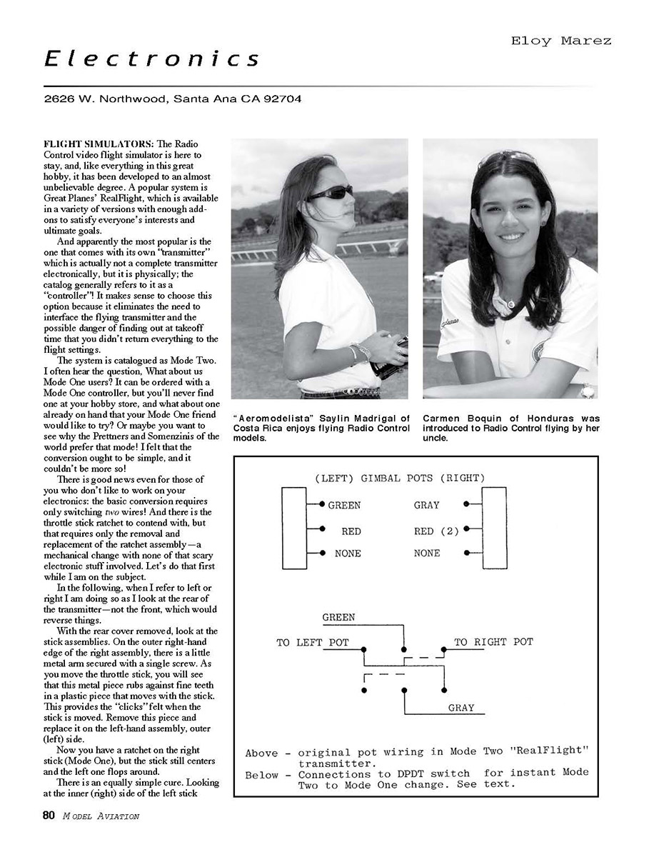
There is good news even for those who don't like to work on electronics: the basic conversion requires only switching two wires. The throttle stick ratchet is another matter, but it requires only removal and replacement of the ratchet assembly—a mechanical change with none of the scary electronic stuff involved. Let's do that first.
In the following, when I refer to left or right I mean as I look at the rear of the transmitter—not the front, which would reverse things.
Mechanical: Moving the Throttle Ratchet and Spring Assembly
- Remove the rear cover and inspect the stick assemblies.
- On the outer right-hand edge of the right assembly, locate the little metal arm secured with a single screw. As you move the throttle stick, this metal piece rubs against fine teeth in a plastic piece that moves with the stick—this provides the "clicks" felt when the stick is moved.
- Remove this metal piece and reinstall it on the left-hand assembly, outer (left) side. This gives you a ratchet on the right stick (Mode One), but the stick will still center and the left stick will be loose.
- To address the centering spring: look at the inner (right) side of the left stick assembly and find the vertically mounted spring that extends as the stick is moved off center. The spring is held at its top by a plastic piece with a screw in its center—this allows stick-tension adjustment.
- Rotate the screw clockwise to the least spring tension, then slip the spring off at both ends (tweezers or locking forceps help).
- Move the spring, the tension-adjusting piece with the screw, and the lever piece to which the spring attaches at the bottom over to the same location on the right stick assembly's inner (left) side. Install the whole spring assembly rotated 180 degrees (the tension screw will be at the top and everything else turned around similarly).
The mechanical transfer is easier to do than to describe. Once you remove the back and study the mechanics, you'll see exactly what must be done.
Electrical: Switching the Potentiometer Wires
Examine the potentiometers—the variable resistors located on the inner and lower sides of the stick assemblies. The only two wires that require switching are on the inner potentiometers:
- The green wire on the left inner potentiometer
- The gray wire on the right inner potentiometer
No other connections need to be switched or made, nor are any adjustments necessary.
Missing Continuation
I could not find any continuation of the article titled "Electronics 2003/01" on the supplied scanned page. The image provided is a "Small-Field Flying" page (Paul Bradley) with photos and captions and does not contain the electronics article text that continues from the prior-page context ("Now for the top- and front-mo..."). Because the required continuation is not present on that page, I cannot extract or correct the remainder of the "Electronics 2003/01" article.
Please either:
- Upload the correct scanned page (page 2 of the Electronics 2003/01 article), or
- If the provided image is correct but only a portion of the page is needed, crop or provide a higher-resolution scan showing the electronics article text.
Once the correct scan is provided, I will extract and correct the remaining article text and continue seamlessly.
Transcribed from original scans by AI. Minor OCR errors may remain.

