
Electronics
Eloy Marez
Misconceptions
We have many misconceptions in Radio Control (RC). Some are new, since there have been and will continue to be major changes in equipment and techniques. Some are old and never seem to go away, but that is to be expected since there is a new crop of RCers born every week.
One of these misconceptions came to light in a letter from a reader in Stilwell, Kansas, who writes:
"You mentioned 'servo reversers,' which brings me to the point. If I need a Futaba S148 to run opposite to its normal direction (in a left and right aileron application) can the red and black wires simply be reversed at the connector? I have asked several people whom I thought might know if the wire switch will work, but I haven't gotten an answer. I haven't tried it for fear of lousing something up."
You did well in not trying this oft-given advice, especially if you are allergic to smoke. Not very long ago I saw this procedure suggested on the Internet, and I was once told by a local flier that a person at one of the largest hobby shops in my area told him that it was the easy way to reverse a servo's rotation. I would guess that this belief exists because it is a known fact that you can reverse the rotation of a common direct current (DC) motor by reversing the polarity of the drive voltage.
Although it is true that the same will happen, and has to happen to a servo motor to reverse the direction of its output, the voltage is applied by the servo amplifier and not directly from the servo plug. The amplifier, like any other electronic circuitry, will not be happy with reverse voltage. It can be a costly mistake because amplifiers, especially those in the more costly servos, are costly themselves. Don't think you can return them to their maker (importer) and claim normal failure. Reverse-voltage damage is readily apparent to a trained technician, and the same type of damage will almost never otherwise occur.
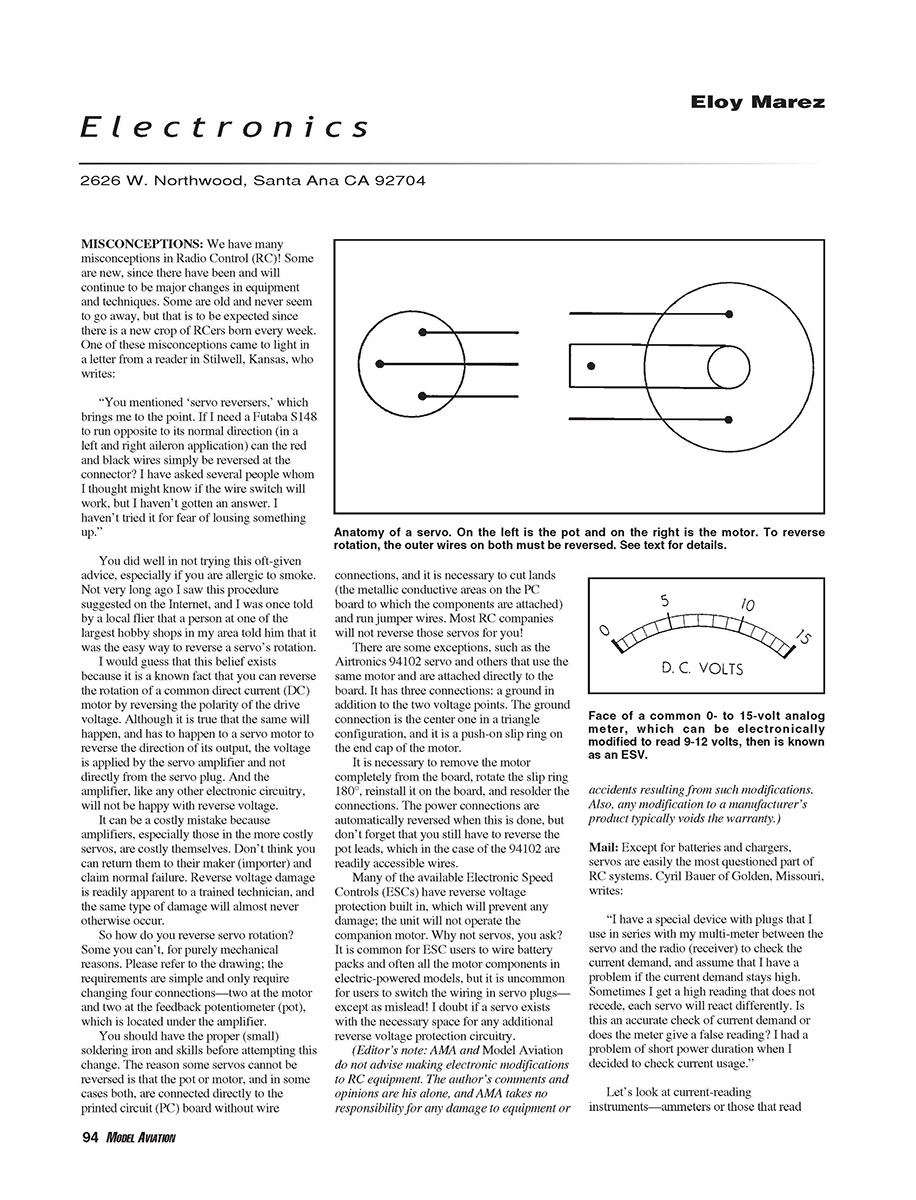
So how do you reverse servo rotation? Some you can't, for purely mechanical reasons. Please refer to the drawing; the requirements are simple and only require changing four connections—two at the motor and two at the feedback potentiometer (pot), which is located under the amplifier. You should have the proper (small) soldering iron and skills before attempting this change. The reason some servos cannot be reversed is that the pot or motor, and in some cases both, are connected directly to the printed circuit (PC) board without wire connections, and it is necessary to cut lands (the metallic conductive areas on the PC board to which the components are attached) and run jumper wires. Most RC companies will not reverse those servos for you.
There are some exceptions, such as the Airtronics 94102 servo and others that use the same motor and are attached directly to the board. It has three connections: a ground in addition to the two voltage points. The ground connection is the center one in a triangle configuration, and it is a push-on slip ring on the end cap of the motor. It is necessary to remove the motor completely from the board, rotate the slip ring 180°, reinstall it on the board, and resolder the connections. The power connections are automatically reversed when this is done, but don't forget that you still have to reverse the pot leads, which in the case of the 94102 are readily accessible wires.
Many of the available Electronic Speed Controls (ESCs) have reverse-voltage protection built in, which will prevent any damage; the unit will not operate the companion motor if reverse-wired. Why not servos, you ask? It is common for ESC users to wire battery packs and often all the motor components in electric-powered models, but it is uncommon for users to switch the wiring in servo plugs—except as misled! I doubt if a servo exists with the necessary space for any additional reverse-voltage protection circuitry.
(Editor's note: AMA and Model Aviation do not advise making electronic modifications to RC equipment. The author's comments and opinions are his alone, and AMA takes no responsibility for any damage to equipment or accidents resulting from such modifications. Also, any modification to a manufacturer's product typically voids the warranty.)
Mail: Servos and Current Measurement
Except for batteries and chargers, servos are easily the most questioned part of RC systems. Cyril Bauer of Golden, Missouri, writes:
"I have a special device with plugs that I use in series with my multi-meter between the servo and the receiver to check the current drawn, and assume that I have a problem if the current demand stays high. Sometimes I get a high reading that does not recede, each servo will react differently. Is this an accurate check of current demand or does the meter give a false reading? I had a problem of short power duration when I decided to check current usage."
Let's look at current-reading instruments—ammeters or meters that read current. Establish an average for each unloaded servo (that is, without a pushrod connected). To do so, cycle the transmitter stick back and forth at a rate that causes the servo to travel continuously to its end points. Get a feel for the servo speed under those conditions, then quickly disconnect the meter and cycle the servo again; any noticeable increase in speed is an indication that you have a poor meter that is causing enough voltage drop to reduce the servo speed.
If, under this unloaded test, "the high reading that does not recede" occurs, you are back to that quality business I discussed before because, like meters, all servos are not created equal. Or it may be that such a servo has a dirty pot or damaged gears.
The next step is to connect the pushrods. First, operate them manually to be sure that there is no binding or excessive friction in the rods or hinges. One or the other could easily be the cause of the short power duration mentioned because it will put more of a load on the servo and increase its current draw.
There will be an increase in the reading with the pushrods connected because the servos will be working harder, and the increase will differ for each control; the loads will not be the same throughout. It is important to watch for high, steady readings at extremes of rotation, which indicate that the servo is bottoming; that is, whatever it is connected to has reached the end of its travel before the servo does. Such occurrences happen most often on the throttle and nose-gear channels.
Receiver Crystals
Cyril also had some service questions. He wrote:
"When I order a radio, do they check it out or do they have lots of radios on all frequencies? Some distributors mention high and low bands. If I order a radio and request high band, what do I get?"
The first part of the question will vary according to brand. Some seem to work well across the relatively small spread of the 72 MHz band, and the crystal set specified will arrive separately. Others will arrive with the proper label on the box and on the equipment. We've come a long way since we used to have to pick crystals that matched and tuned the receiver to its companion transmitter.
Some makers split the 72 MHz band in half—a low-band system being one that operates on the 11 to 35 channel frequencies, and 36 to 60 designated as their high band. This does not necessarily mean greater frequency accuracy; it can be a requirement of the circuitry and/or crystals being used.
Go fly! The stuff works well in spite of the misconceptions!
MA
ESV Misconceptions
What is an ESV?
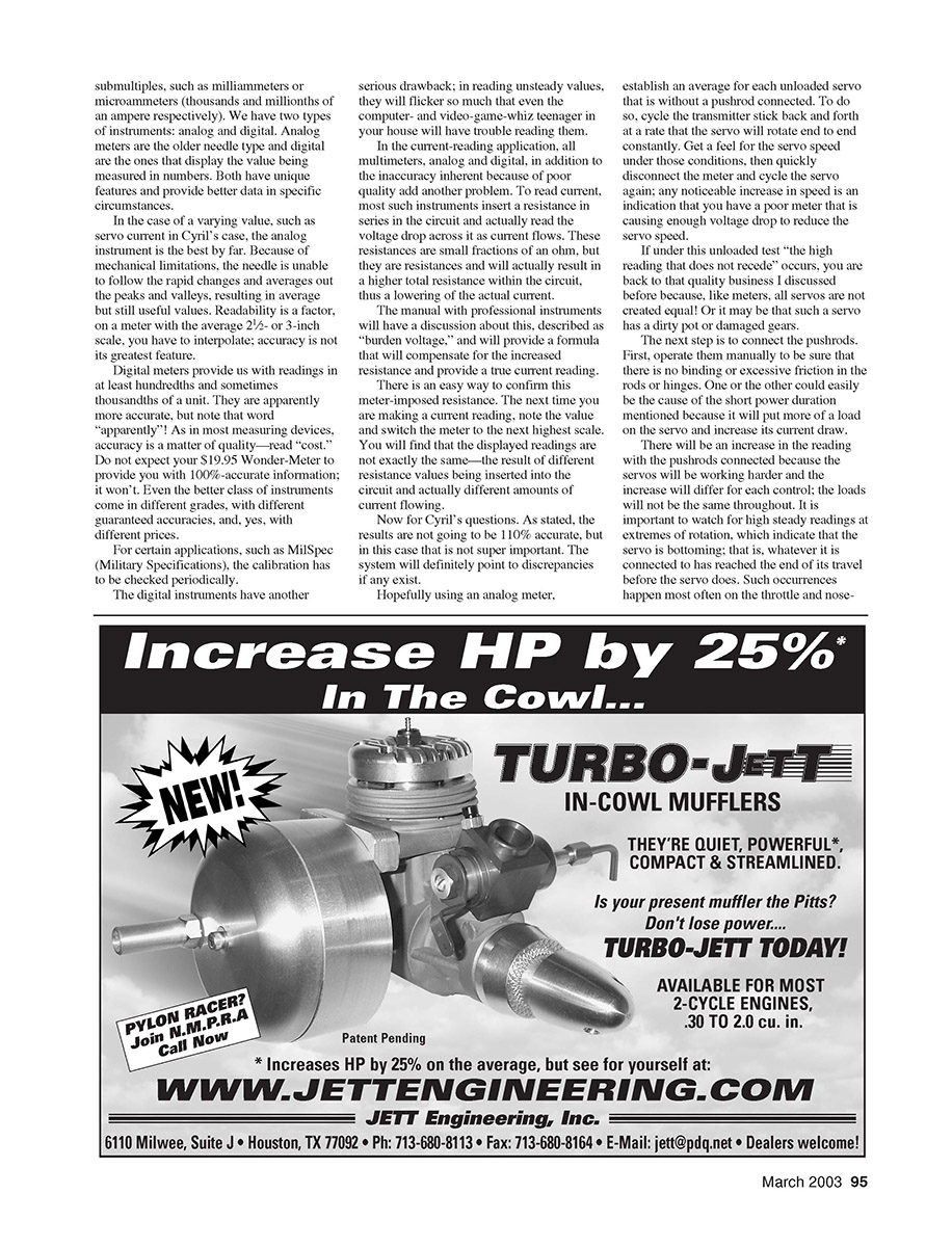
Since we have touched on the subject of meters, it seems a good time to discuss Expanded Scale Voltmeters, or ESVs. The term can be applied correctly only to analog meters; digital meters are something else entirely.
An expanded-scale meter is one to which electronic circuitry has been added, tailoring it to display a narrower range of values. The basic analog meter might be intended to read 0.0–15.0 volts. If we use such a meter to read the 9.6 nominal volts of an RC transmitter battery, it will be difficult to read an exact value and impossible to discern small differences.
To increase readability, the added circuitry can change the meter to read, for example, from 9.0 to 12.0 volts. A 9.6-volt Ni-Cd battery will read considerably higher when first charged. With such a change, there will be no movement with any voltage less than 9.0 volts and the needle will peg at the right-hand side with a voltage greater than 12.0 volts, but it is possible to read 9.6 and small variations with greater accuracy.
A commercially manufactured instrument will have the proper markings on the meter face; home-brewers will have to change them or just remember the new values. That is an ESV.
Loads and How to Calculate Them
In RC, many such instruments made especially for us place a calculated load on the battery, which will read differently with and without the load. Although the load feature is a good idea, we had an ESV without it.
What's the load? A simple resistor that will draw current from the battery—50% of the battery capacity in milliamperes (mA) is recommended. Using Ohm's law (resistance in ohms equals voltage divided by current in amperes), we can arrive at the required resistor value for any given battery.
Example:
- Take a common 600 milliampere-hour (mAh) 9.6-volt transmitter battery, which we wish to load at 300 mA.
- Resistance: 9.6 volts ÷ 0.3 amp = 32 ohms. The nearest standard values are 30 and 33 ohms; either will do the job.
- Wattage: Power (watts) = voltage × current. Here, 9.6 volts × 0.3 amp = 2.88 watts. Standard resistor wattage ratings of 3 W or 5 W are usable; 5 W is actually a better choice because it will run cooler and dissipate heat more safely.
In purchasing resistors, specify the wattage rating of the unit.
Digital Meters and Loads
There is no such thing as a digital ESV, except perhaps in the RC marketplace. The inherent greater accuracy of digital instruments does not require any expanding of the display—they will automatically read small variances in voltage, subject to their basic quality.
Digital voltmeters can and are provided with loads as explained, and a common non-RC meter can have such a load added simply by connecting the proper resistor across the meter leads while the battery voltage is being read.
Transcribed from original scans by AI. Minor OCR errors may remain.

