
Electronics
Eloy Marez
Surface Mount Technology (SMT)
Surface Mount Technology (SMT) is the latest electronic assembly methodology and includes unique components and assembly methods. It is responsible for the extremely small, lightweight, very reliable, and inexpensive electronics now available to us.
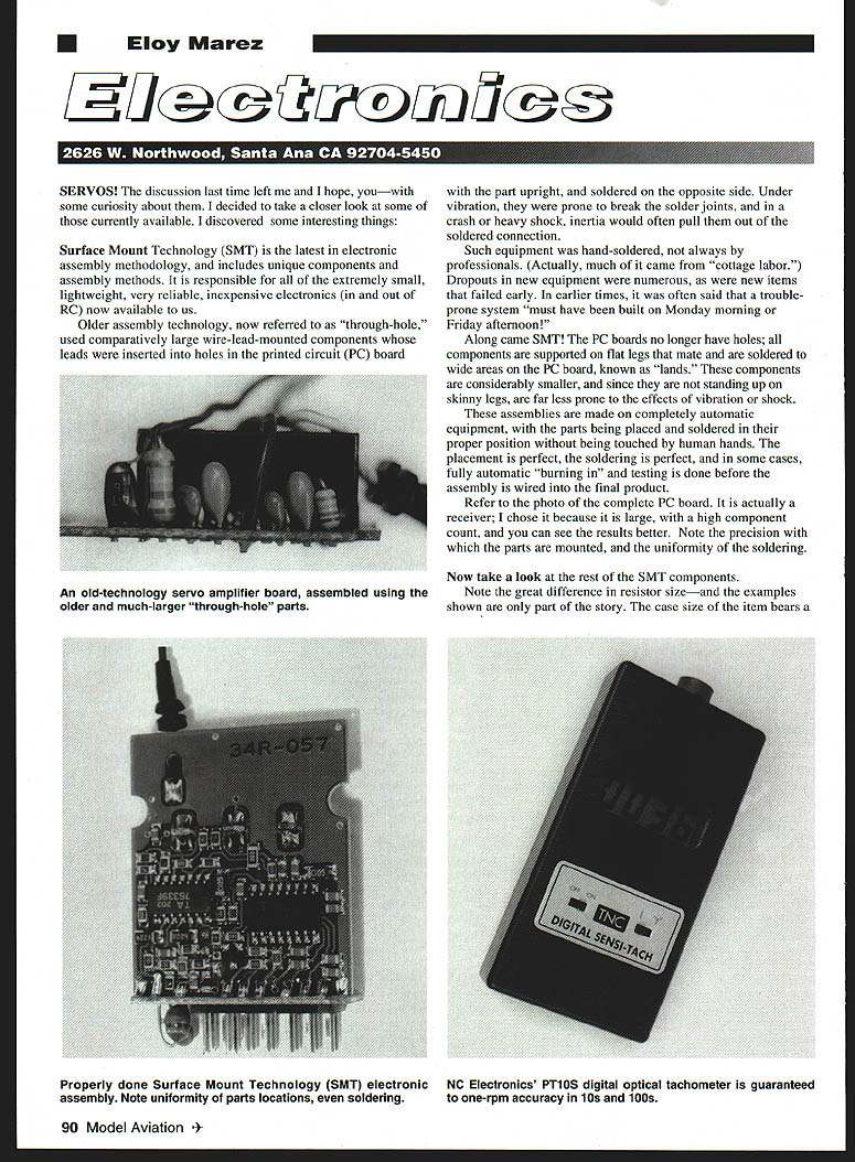
Older assembly technology, now referred to as "through-hole," used comparatively large wire-lead-mounted components whose leads were inserted into holes in the printed circuit (PC) board with the part upright, and soldered on the opposite side. Under vibration they were prone to breaking the solder joints, and in a crash or heavy shock inertia would often pull them out of the soldered connection.
Such equipment was hand-soldered, not always by professionals. (Much of it came from "cottage labor.") Dropouts in new equipment were numerous, as were new items that failed early. It was often said that a trouble-prone system "must have been built on Monday morning or Friday afternoon!"
With SMT, PC boards no longer have holes; components are supported on flat legs that mate and are soldered to wide areas on the PC board known as "lands." These components are considerably smaller, and since they are not standing up on skinny legs they are far less prone to the effects of vibration or shock.
SMT assemblies are made on completely automatic equipment, with parts placed and soldered in their proper positions without the benefit of human hands. Placement is precise, soldering is uniform, and in some cases fully automatic "burning in" and testing is done before the assembly is wired into the final product.
Refer to the photo of the complete PC board (a receiver). I chose it because it is large with a high component count so you can see the results better. Note the precision with which the parts are mounted and the uniformity of the soldering.
Note the great difference in resistor size — and the examples shown are only part of the story. The case size of the item bears a number, such as 0805 or 1206 for resistors; these indicate the actual size in hundredths of an inch:
- 0805 = 0.08 inch long by 0.05 inch wide
- 1206 = 0.12 inch long by 0.06 inch wide
Chip resistors are now available in 0402 case size; you can do your own calculations in hundredths of an inch.
All other SMT components are similarly reduced in size. For example, on the receiver board, the two larger components in the middle are integrated circuits (ICs). Significant size reductions have taken place in ICs; the active element inside is often much smaller than the package. The package is larger for ease of handling and for soldering into the circuit.
Servos
I discovered several interesting things, mostly about aftermarket cheaper servos (those available from companies other than the major RC system manufacturers).
- Many such servos, regardless of label or package, come from the same manufacturer: Grand Wing Servo-tech Co. in Taiwan. Often the only differences are wiring and sometimes color. That is not necessarily bad; there are excellent electronic products from Taiwan.
- Some SMT servos are not made by automatic equipment but are obviously put together by hand. This is undesirable for a couple of reasons: the components don't line up as neatly, and the soldering is not as uniform. Uniform soldering is a major reliability factor.
- Surface mount components (SMCs) are rated for soldering temperature and the time the temperature can be applied. If overdone, component values and expected life can be affected. Hand soldering SMCs with handheld irons greatly increases the chance of overheating, which will likely reduce life and reliability.
- Some servos advertised as SMT are actually the old-fashioned wire-lead type. Those servos can work, but it makes you question the labeling.
You cannot expect the same performance and reliability from a $10 servo as from a $50 servo. If you fly expensive airplanes or ones you've built yourself, using cheap servos for throttle and minor functions is acceptable, but saving money by using them for main flight controls can be false economy. You get what you pay for.
The same applies to all radio equipment. Another point to look for is the connectors: some use plain silver-colored contacts, while others are gold-plated. Gold-plated contacts have less contact resistance, are less likely to corrode, and are preferred.
Price makes a difference in many items, for example, tachometers.
Tachometers and Calibration
The first tachometer aimed primarily at modelers was the Heath Thumb Tach from the now-disappeared Heathkit Company. We appreciated it despite its limitations: it read 0–25,000 rpm on an analog scale about 1½ inches wide and required ideal lighting to get a good reading.
Other analog instruments appeared; no doubt the best was the Royal Products ProTach, which used expanded-scale techniques for smaller and more accurate readings.
When digital readouts and related circuitry appeared, they quickly found their way into modelers' tachometers. As with servos, all types have their place — even a Thumb Tach is better than no tach if you are serious about engine operation.
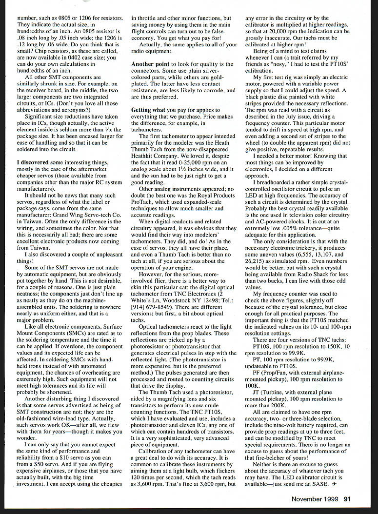
For the serious, more-involved flier there is a superior option: digital tachometers from TNC Electronics (2 White's Ln., Woodstock NY 12498; Tel.: [914] 679-8549). Before listing versions, a bit about optical tachs:
Optical tachometers react to light reflections from the prop blades. These reflections are picked up by a photoresistor or phototransistor that generates electrical pulses in step with the reflected light. The phototransistor is more expensive but is the preferred method. The pulses are processed and routed to counting circuits that drive the display.
The Thumb Tach used a photoresistor aided by a magnifying lens and six transistors for counting. The TNC PT10S includes a phototransistor and eleven ICs, any one of which can contain hundreds of transistors. It is a very sophisticated, advanced piece of equipment.
Calibration of any tachometer greatly affects accuracy. It is common to calibrate these instruments by aiming them at a light bulb that flickers 120 times per second; the tach reads this as 3,600 rpm. That's fine at 3,600 rpm, but any error in the circuitry or calibration is multiplied at higher readings, so at 20,000 rpm the indication can be grossly inaccurate. Tachs must be calibrated at higher rpm.
I tested the PT10S' calibration. My first test rig was an electric motor powered with a variable supply and a black plastic disc painted with white stripes for reflection. The PT10S was read with a circuit driving a frequency counter. The motor tended to drift in speed at high rpm, and adding a second set of stripes (to double apparent rpm) did not give repeatable results.
I needed a better source. I breadboarded a simple crystal-controlled oscillator circuit to pulse an LED at high frequencies. The accuracy of such a circuit is determined by the crystal. A commonly available crystal (used in television color circuitry and AC-powered clocks) is cut to an extremely low ±0.005% tolerance — adequate for this application.
With the necessary electronic trickery, it produces some uneven simulated rpm values (6,555; 13,107; and 26,215). Even numbers would be better, but with such a crystal available from Radio Shack for less than two dollars, I can live with those odd values.
My frequency counter checked the above figures (slightly off because of crystal tolerance but close enough). The important thing is that the PT10S matched the indicated values on its 10- and 100-rpm resolution settings.
TNC offers four versions:
- PT10S — 100 rpm resolution to 150,000 rpm
- PT — 10 rpm resolution to 99,900 rpm
- PF (Prop/Fan) — 100 rpm resolution to 100,000 rpm, with external airplane-mounted pickup
- JT (Turbine) — 100 rpm resolution to more than 200,000 rpm, with external plane-mounted pickup
All are claimed to have one-rpm accuracy, two- or three-blade selection, include the required nine-volt battery, can provide prop readings at up to three feet, and can be modified by TNC to meet special requirements.
There is no longer an excuse to guess about the performance of that fire-belcher of yours — nor an excuse to guess about the accuracy of whatever tach you have. The LED calibrator circuit is available — send a SASE.
Transcribed from original scans by AI. Minor OCR errors may remain.

