
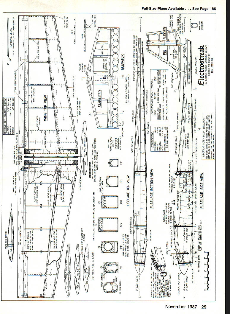
Electrostreak
Electric-powered models have proven they can fly for extended periods, go fast, and climb with authority. This model combines all three in a go-for-broke aerobatic configuration that changes opinions about electrics wherever it's flown. For four-channel control and .05-size motors. — Tom Stryker
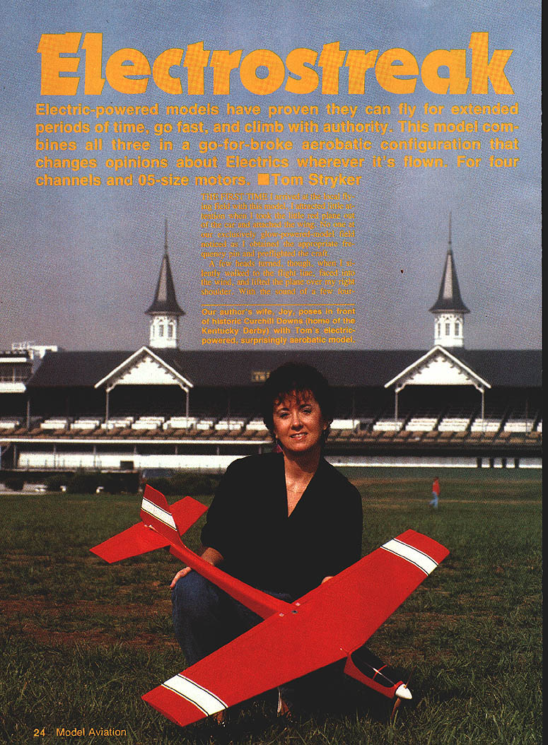
The first time I arrived at the local flying field with this model, I attracted little attention. When I took the little red plane out of the car and attached the wings, no one at our exclusively glow-powered field noticed as I obtained the appropriate frequency pin and preflighted the craft.
A few heads turned, though, when I silently walked to the flight line, faced into the wind, and lifted the plane over my right shoulder. With the sound of a few four-strokers flying in the background, the Electrostreak could not be heard at all as I launched it and let it gracefully climb to altitude.
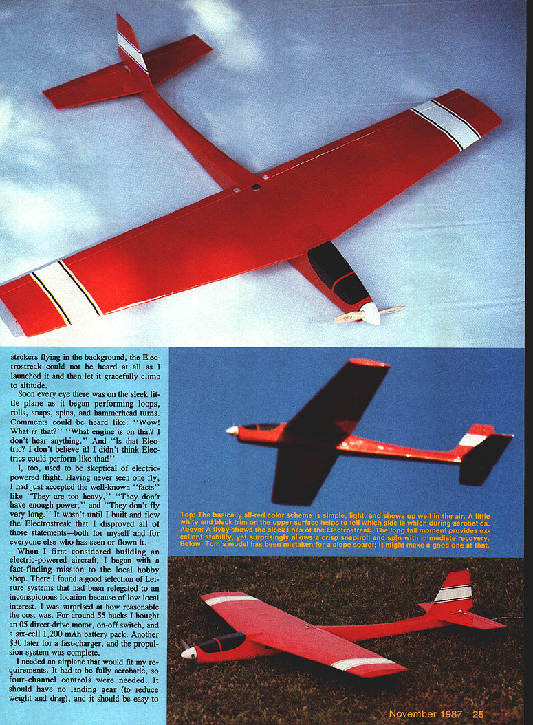
Soon every eye was on the sleek little plane as it began performing loops, rolls, snaps, spins, and hammerhead turns. Comments could be heard like: "Wow! What is that?" "What engine is on that? I don't hear anything." and "Is that electric? I don't believe it! I didn't think electrics could perform like that!"
I, too, used to be skeptical of electric-powered flight. Having never seen one fly, I had just accepted the well-known "facts" that they were too heavy, didn't have enough power, and didn't fly very long. It wasn't until I built and flew the Electrostreak that I disproved those statements—for myself and for everyone else who has seen or flown it.
Design goals and components
- Fully aerobatic: four-channel controls.
- No landing gear: to reduce weight and drag; intended for hand launch and grass landings.
- Shoulder-wing layout: easy hand launching.
- Sleek appearance: avoid unsightly cooling holes in the bottom fuselage.
- Flow-through cooling: air is forced just below the spinner, travels through the fuselage, and exits under the elevator.
- Semi-symmetrical airfoil and tapered wing planform based on Jim Denaro's Taper Ace (drawn-rib tapered wing).
Propulsion and cost:
- I found O.S. direct-drive motors locally for a reasonable cost. For around $55 I bought an O.S. direct-drive motor, an on-off switch, and a six-cell, 1,200 mAh battery pack. Another $30 for a fast charger completed the propulsion system.
- Motors used on the prototype: Leisure .05 competition-wind motor and later an Astro Cobalt .05.
Adhesive and build approach:
- Built entirely with medium-viscosity Super Jet cyanoacrylate (CyA). No fuel-proofing needed.
- Construction goes quickly—less to build than a glow-engine ship, and no landing gear reinforcements are required.
Materials and preparation
- Take a trip to the hobby shop with a postal scale; select the lightest balsa available. Exceptions: the 1/4" and 3/16" sheets used for wing spars and stabilizer parts.
- Use very light 1/16" balsa (four- to six-pound contest grade) for ribs and sheeting where indicated (available from Sig Mfg. Co. or Lone Star Models).
- Cut formers, ribs, and parts accurately and trial-fit often.
Wing construction
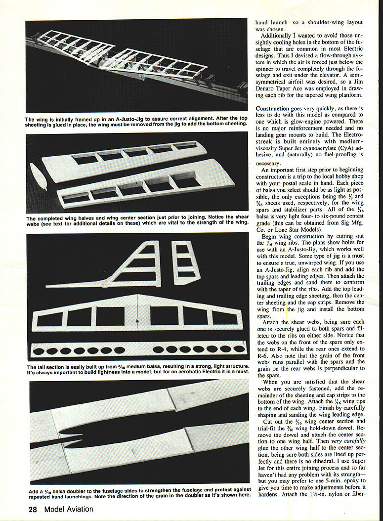
- Cut out the 1/16" wing ribs. The plans show jig holes for use with an A-Justo-Jig — some type of jig is a must to ensure a true, unwarped wing.
- Using the A-Justo-Jig, align ribs and add top spars and leading edges.
- Attach trailing edges and sand them to conform to the taper of the ribs.
- Add top leading- and trailing-edge sheeting, center sheeting, and cap strips.
- Remove the wing from the jig and install bottom spars and shear webs. Fillet shear webs to the ribs on either side and ensure they are securely glued to both spars.
- Note: front shear webs extend to R-4; rear shear webs extend to R-6.
- Note: grain direction — front webs' grain runs parallel to the spars; rear webs' grain runs perpendicular to the spars.
- When satisfied the shear webs are secure, add the remainder of bottom sheeting and cap strips.
- Attach 1/16" wing tips and carefully shape and sand the wing leading edge.
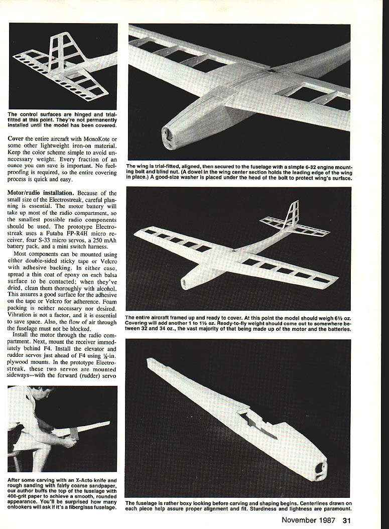
- Cut out the 1/16" wing center section and trial-fit the 1/16" wing hold-down dowel. Remove the dowel and attach the center section to one wing half, then glue the other wing half to the center section. Be sure both sides are perfectly aligned — there is no dihedral.
- I used Super Jet for the wing join; some builders may prefer 5-minute epoxy to allow time for adjustment.
- Install the 1/2" nylon or fiber wing hold-down dowel.
- Use glass reinforcing tape with Super Jet or epoxy and insert the wing hold-down dowel after joining.
Tail and control surfaces
- Tail surfaces are built with 3/32" medium balsa, resulting in a strong, light structure. Assemble parts over the plans and ensure good fits in corners.
- Taper the rear of the rudder and elevator and cut lightening holes in the elevator with a Dremel sanding drum (or similar).
- Sand a V-shape on the front of the rudder and elevator and slot them for hinges.
- Add a balsa doubler to the fuselage sides to strengthen the fuselage and protect against repeated hand launches. Note grain direction per plans.
Control linkages:
- Ailerons: use 1/8" x 1/4" aileron stock; cut hinge slots and install ailerons after joining the wing.
- Elevator pushrod: 1/4" balsa pushrod.
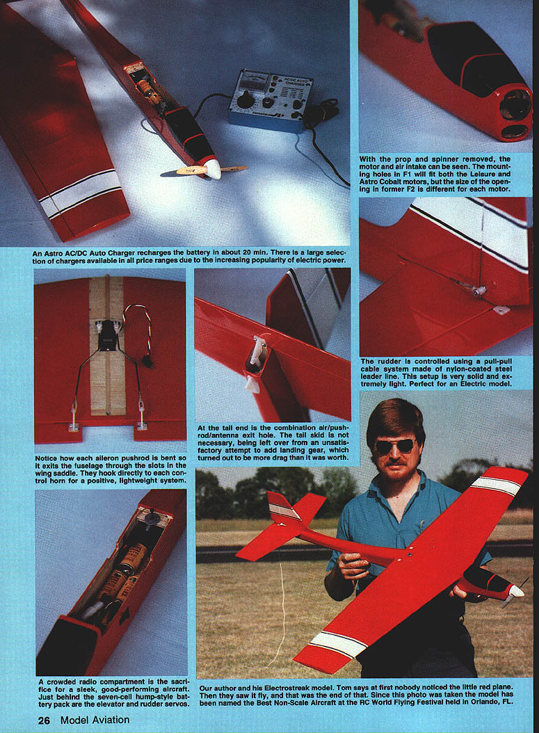
- Rudder: controlled with a pull-pull cable system made of nylon-coated steel leader line — very light and solid.
- Each aileron pushrod is bent so it exits the fuselage through slots in the wing saddle and hooks directly to each control horn for a positive, lightweight system.
- Typical hinge locations and additional construction details are shown on the plans.
Fuselage construction and assembly
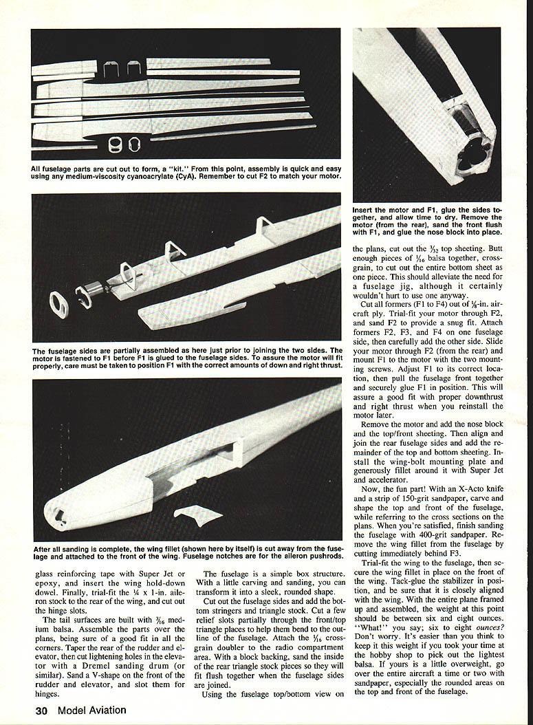
- Cut formers F1–F4 from 1/16" aircraft plywood.
- Install F2–F4 on one fuselage side and pin the fuselage sides together. Trial-fit the motor through F2 and sand F2 for a snug fit.
- Insert the motor through F2 (from the rear) and attach F1 to the motor with the mounting screws. Adjust F1 to its correct location to ensure the proper downthrust and right thrust when the motor is reinstalled.
- Pull the fuselage front together and securely glue F1 in position. After glue is set, remove the motor and sand the front flush. Glue in the nose block.
- Add fuselage top and bottom sheeting, wing-bolt mounting plate (1/8" ply), and blind nut as shown on the plans. Generously fillet around the wing-bolt plate with Super Jet and accelerator.
- Carve and shape the top and front of the fuselage with an X-Acto knife and 150-grit sandpaper, referring to cross sections on the plans. Finish with 400-grit sandpaper.
- Remove the wing fillet from the fuselage by cutting immediately behind F3. Trial-fit the wing, tack-glue the stabilizer in position and ensure close alignment with the wing.
- When framed up and assembled, weight at this point should be between six and eight ounces if very light balsa was selected. If overweight, sand rounded areas on the top and front of the fuselage to save ounces.
Additional details:
- Cut out fuselage sides and add bottom stringers and triangle stock. Cut relief slots in front/top triangle pieces to help them bend to outline.
- Attach 1/16" cross-grain doubler to the radio compartment area. Back the rear triangle stock pieces and sand their inside to fit flush when the fuselage sides join.
Covering and finish
- Cover the aircraft with MonoKote or another lightweight iron-on material. Keep the color scheme simple to avoid unnecessary weight.
- No fuel-proofing is required; the covering process is quick and easy.
- Install reinforcing cloth and glass tape where indicated.
Motor and radio installation
Because of the small size of the Electrostreak, careful planning is essential.
Recommended prototype components:
- Receiver: Futaba FP-R4H micro receiver.
- Servos: four S-33 micro servos (ailerons, elevator, rudder, throttle).
- Radio battery: 250 mAh pack and a mini switch harness.
Mounting:
- Most components can be mounted using double-sided sticky tape or Velcro with adhesive backing. Spread a thin coat of epoxy on each balsa surface to be contacted; when dry, clean with alcohol to provide a good adhesive surface.
- Foam packing is neither necessary nor desired. Save space and avoid blocking airflow through the fuselage.
- Install the motor through the radio compartment. Mount the receiver immediately behind F4.
- Install elevator and rudder servos just ahead of F4 using 1/8" plywood mounts. In the prototype, the rudder servo is mounted 1/2" higher than the elevator servo to allow clearance for pull-pull cables.
- The elevator uses a conventional balsa pushrod; the rudder uses the light pull-pull cable system.
- Mount the motor switch directly to the side of the throttle servo; both are installed just rear of F3. The battery is mounted across from and a bit forward of the throttle servo, straddling the side post of F3. Use Velcro or sticky tape strips ahead of and behind F3 to secure it.
- A six-cell 1,200 mAh pack fits in the radio compartment. If you use seven cells, the seventh cell may have to be positioned toward the rear and rotated 90° to clear the aileron pushrods.
- Aileron servo is mounted with 3/8" ply mounts and situated as deep into the wing as possible. The two bends in each aileron pushrod allow exit through the fuselage and provide direct hookups to each aileron. The pushrod exit slots also help cooling airflow.
Charging
- Refer to the instructions for your particular battery/charger combination. Hobby shops can be helpful because of the popularity of electrics.
- Most chargers fully charge a battery in 15 minutes; in practice I have found it takes about 20 minutes.
- As a rule, most batteries feel warm to the touch when fully charged, but follow the battery/charger instructions.
- If your charger has AC capability, consider doing the first charge at home so you arrive at the field ready.
- The 1,200 mAh cells seem to work best for this application. They deliver constant power until almost exhausted and then drop off quickly. Smaller cells (800 mAh, etc.) sometimes provide good early power and gradually taper off, which can be annoying during aerobatic sequences.
Flying
- Choose a prop per the plans or motor manufacturer's recommendations and balance the prop carefully. If you use a wooden prop, take extras—gear-less landings can occasionally cost you one.
- Recheck the model's balance front-to-rear and side-to-side before flight.
Hand-launch procedure:
- Hold the model at the center-of-gravity (CG) with one hand and the transmitter in the other.
- Trott a few steps forward and toss it level. For the first test flight, add a few clicks of up-elevator trim to prevent an immediate dive.
- Allow a few seconds of level flight to build speed before climbing or performing maneuvers.
Flight experience and motors:
- The Electrostreak was first flown with a Leisure .05 motor, Cox gray 6x4 prop, and a six-cell 1,200 mAh pack. Straight-and-level flight was fast; climb rate was modest but aerobatics were possible.
- Replacing the Leisure motor with an Astro Cobalt .05 and using a seven-cell Sanyo 1,200 mAh pack improved climb and speed noticeably. Performance then allowed loops with snap rolls on top, four- and eight-point rolls, square loops, and successive rolls across the field.
Flight times and landing:
- Typical airborne time seems to be in the seven- to nine-minute range—enough for an aerobatic routine.
- Flight times can be extended by climbing, turning off the motor, and gliding; then restart the motor to climb again.
- When the battery begins to give out, set up your landing pattern. Battery power will usually drop off over about a minute, giving time to reach the runway.
- Be sure the motor is off prior to touchdown. The Leisure motor will often windmill down and the prop flattens in the grass; the Astro Cobalt has more compression and the prop usually stops as the plane slows.
- If the prop stops vertical, a quick throttle bump may help. You may occasionally break a wooden prop ($1.50), but that's about the only regular expense.
Recommended control throws
- Ailerons: 5/32" each way
- Elevators: 1/4" up and down
- Rudder: 1/2" each way
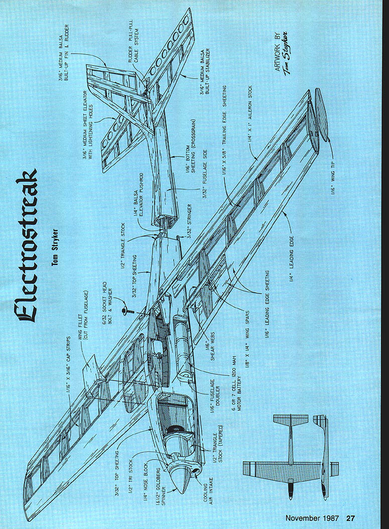
Parts and materials (from plans)
- 3/32" medium balsa built-up fin & rudder
- Rudder pull-pull cable system
- 3/32" medium sheet elevator with lightening holes
- 1/4" balsa elevator pushrod
- 1/2" triangle stock
- 3/32" top sheeting
- 1/16" bottom sheeting (crossgrain)
- 3/32" stringer
- Fuselage side
- 1/16" leading edge sheeting
- 1/16" leading edge
- 1/8" x 1/4" wing spars
- 1/16" shear webs
- 1/16" wing ribs
- 1/16" wing tip
- 1/8" x 1/4" aileron stock
- Cooling air intake
- 1/4" nose block
- 1/8" nose block spinner
- 6- or 7-cell 1,200 mAh motor battery
- 1/16" fuselage doublers
- Wing bolt mounting plate 1/8" ply
- 0-32 blind nut
- Lightening holes recommended (install after wing is joined and reinforcing cloth is attached)
- Typical hinge locations shown on plans
Notes
- A crowded radio compartment is the sacrifice for a sleek, high-performing aircraft. On the prototype, the battery hump occupies much of the compartment, with elevator and rudder servos just behind it.
- Artwork and photography by Tom Stryker. The Electrostreak has been named Best Non-Scale Aircraft at the RC World Flying Festival in Orlando, FL.
Transcribed from original scans by AI. Minor OCR errors may remain.

