
Elf Biplane Senior
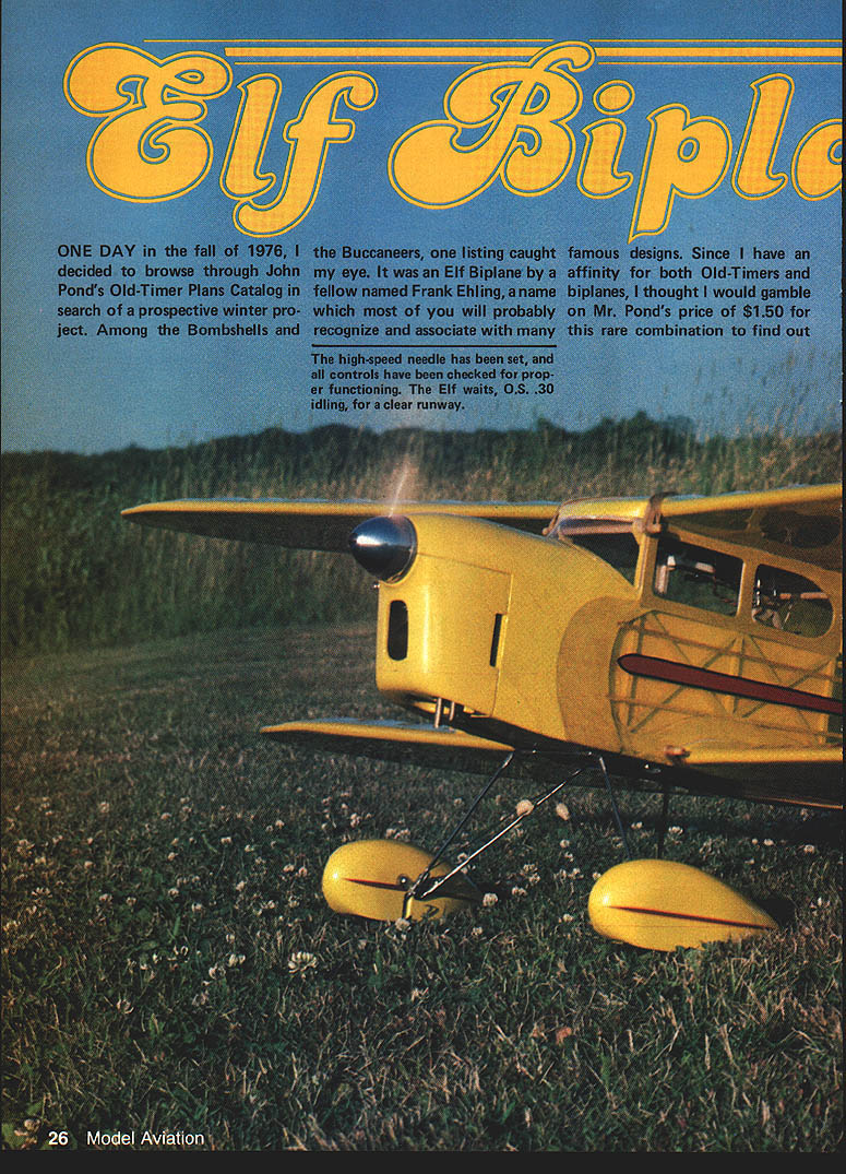
ONE DAY in the fall of 1976 I decided to browse John Pond's Old-Timer Plans Catalog in search of a winter project. Among the Bombshells and Buccaneers one listing caught my eye: an Elf Biplane by Frank Ehling. Since I have an affinity for both Old-Timers and biplanes, I gambled on Pond's $1.50 price for this rare combination and ordered a couple sets of plans.
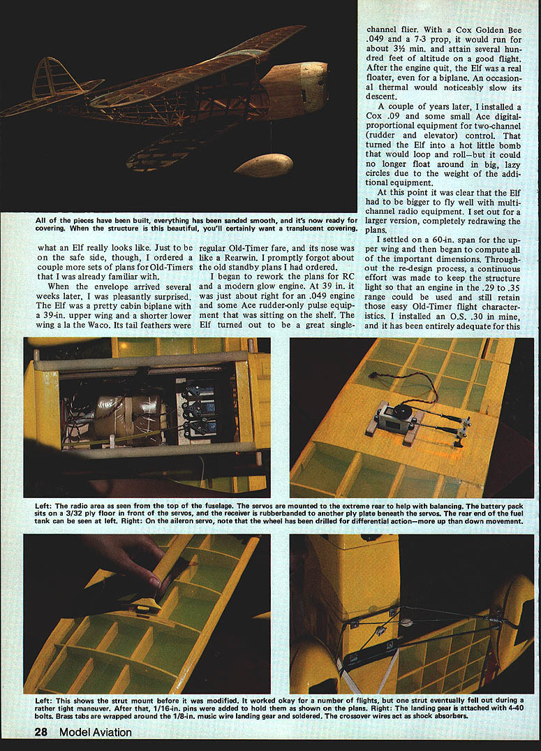
When the envelope arrived several weeks later I was pleasantly surprised. The Elf is a pretty cabin biplane with a 39‑in. upper wing and a slightly shorter lower wing a la Waco. Its tail feathers are channel‑flier style and the nose resembles a Rearwin. With a Cox Golden Bee .049 and a 7x3 prop it would run about 3–3½ minutes and attain several hundred feet; after the engine quit the Elf was a real floater — an occasional thermal would noticeably slow its descent.
A couple of years later I installed a Cox .09 and some small Ace digital proportional equipment for two‑channel (rudder and elevator) control. That turned the Elf into a hot little bomb that would loop and roll, but it could no longer float in big lazy circles because of the added weight. It became clear the Elf would have to be larger to fly well with multichannel radio gear.
I set out to design a larger version, completely redrawing the plans, and settled on a 60‑in. span for the upper wing. Throughout the redesign I worked to keep the structure light so engines in the .29–.35 range could be used while retaining easy Old‑Timer flight characteristics. I installed an O.S. .30 and it proved entirely adequate.
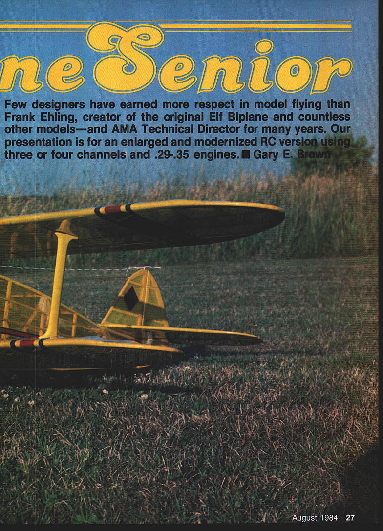
Gary E. Brown
Design and General Notes
- Purpose: an enlarged, modernized RC version of the original Elf Biplane for three or four channels using .29–.35 engines.
- Typical power:
- Original single‑channel: Cox Golden Bee .049 (7x3 prop)
- Upgraded: Cox .09 or O.S. .30 (installed in the 60‑in. version)
- A Schnuerle‑type .25 will probably suffice; avoid anything larger than a .40.
- Finished weight: about 5 lb.
- Appearance: semi‑scale cabin biplane with a clean enclosed muffler cowl and optional wheel pants.
Radio and Control Layout
- Radio area is on the top of the fuselage.
- Servos are mounted toward the extreme rear to help balance; battery pack sits on a 3/32" plywood floor.
- Front servos and receiver are rubber‑banded to another ply plate beneath the rear servos.
- The fuel tank is located toward the rear (tank floor glued in after determining position).
- Aileron servo is mounted for drilled differential action — more up than down movement.
- Control configuration:
- Two‑channel: rudder and elevator (hot, aerobatic with heavier gear)
- Three‑channel option: rudder, elevator, ailerons — plans include suggested increased rudder/fin sizes and dihedral values for conservative three‑channel flight.
Construction
Before beginning, study the plans thoroughly. Construction techniques are typical of Old‑Timers, but note two important points:
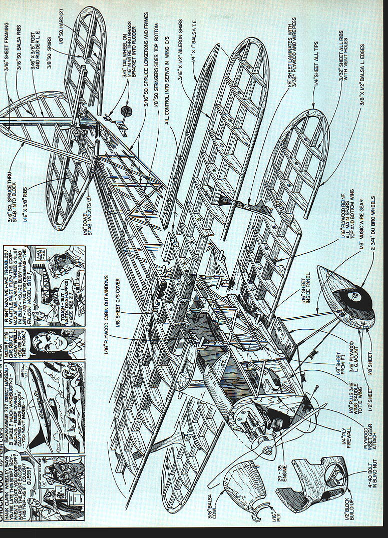
- Do not omit the 3/32" plywood front top wing dowel mount; it extends from the top of the cabin down to the plywood landing gear mount and carries significant load.
- The 1/8" sheet balsa wedge between the fuselage and stabilizer gives positive incidence to the stab; the stab is secured with three dowels.
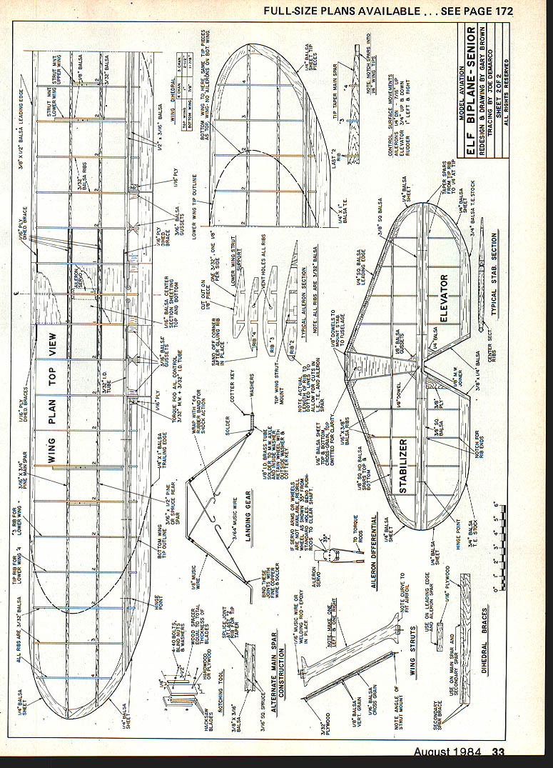
Wings
- Cut all parts first. Make two 1/16" plywood templates of the No. 2 rib, sandwich the balsa No. 2 ribs between them, and gang‑sand to finished dimensions.
- While ribs are stacked, cut notches for spars and cut off tails at the aileron spar.
- Even if you plan to build without ailerons, include the aileron spar if you might add them later.
- Spars:
- Aileron spar: firm to hard 1/8" x 3/16" balsa; tips tapered after assembly.
- Front spars: sawn from 3/8" plank of knotless spruce (or straight‑grained pine to 3/16" thickness as alternate).
- Rear spar: 3/16" x 1/2" pine or spruce.
- If you lack the power tools to cut a 3/16" x 3/4" main spar, laminate a 3/8" x 3/16" balsa strip between two 3/16" square spruce pieces. A splice joint may be needed where the spar begins to taper at the last No. 2 rib.
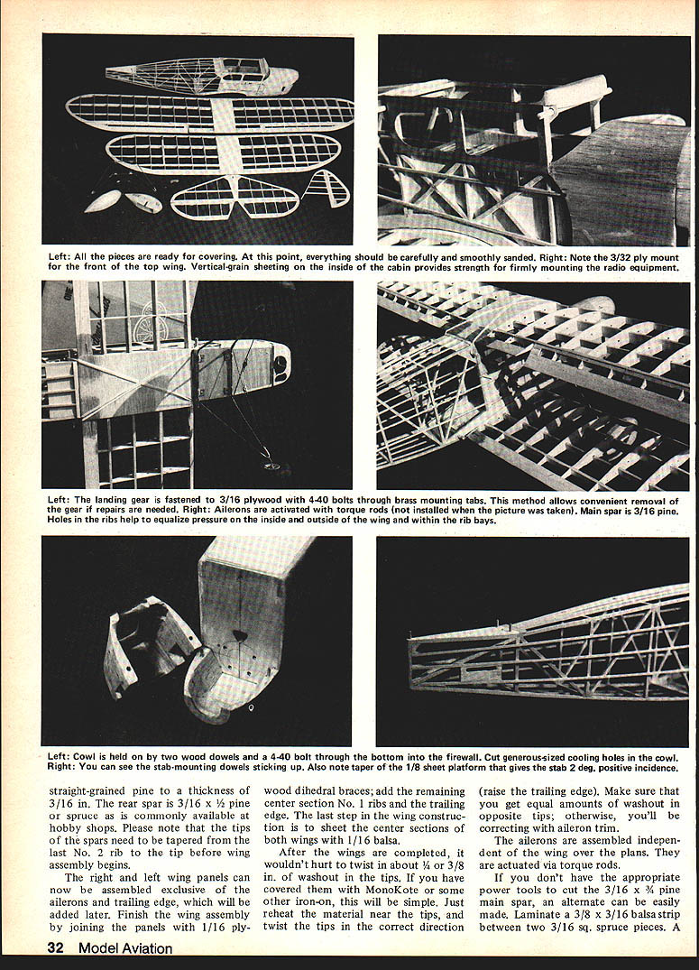
- Assembly:
- Assemble right and left panels (exclusive of ailerons and trailing edges), join with 1/16" plywood dihedral braces, add center No. 1 ribs and trailing edge, then sheet center sections with 1/16" balsa.
- Tip washout: twist in about 1/4" to 3/8" of washout in the tips (raise the trailing edge) — easiest if covering with MonoKote: reheat at tips and twist; ensure equal washout both sides.
- Ailerons:
- Assemble independent of wing over the plans; actuated via torque rods.
- Reinforcement:
- Wrap trailing edge dihedral joints at the center section with fiberglass cloth and a couple coats of epoxy for strength and protection before covering.
- Notches for ribs in leading edge and aileron spar can be cut with a simple tool made of two wood pieces sandwiching two or three hacksaw blades; adjust width/depth by adding or removing blades.
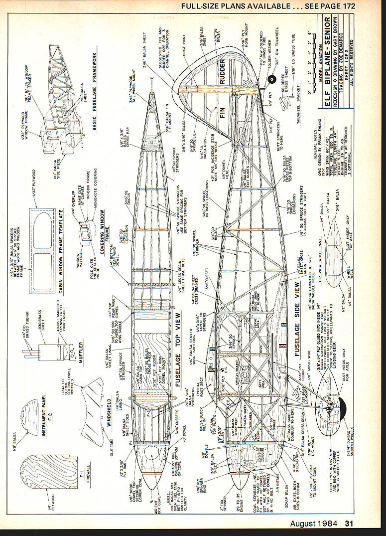
Fuselage
- Build two side frames from 3/16" sq. spruce and balsa, pin over plans; longerons are 3/16" sq. spruce.
- After first side dries, assemble the second directly on top of the first. Laminate 1/8" balsa wing saddle doublers to inside of each fuselage side (doubler extends only to front of landing gear mount).
- Join sides at wing trailing edges, top and bottom, with 1/4" balsa plates; ensure sides are parallel forward of these points.
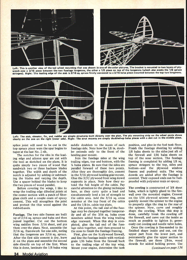
- Cement in 3/16" plywood landing gear mount and glue 3/32" plywood front wing dowel supports — these extend full height of the cabin and are critical load carriers.
- Add 3/16" sq. cross members at top front of cabin and 1/8" cabin top plate.
- Clamp tail end, add 3/16" sq. balsa cross members from wing trailing edge rearward, then glue tail end of fuselage sides together and finish nose framing.
- Glue on 1/4" plywood firewall, line fuselage inside with vertical grain 1/16" balsa from firewall back to trailing edge of top wing, mount engine and glue in fuel tank floor.
- Finish fuselage sheeting:
- Add 1/8" balsa sheets to sides just aft of firewall.
- Add 1/16" balsa sheets on top of nose section.
- Add 1/8" square spruce stringers to top, sides and bottom; add plywood window frames and pushrod exits.
- Wing dowels are added after fuselage is covered; exposed ends can be fuel‑proofed with polyester resin or epoxy.
Cowling
- Construct cowling from 3/8" sheet balsa, lightly glued to the firewall over the mounted engine.
- Cement 1/16" plywood spinner ring, mount spinner to align ring, then carve and rough shape cowling.
- Break cowling off firewall, hollow the inside to lighten it, and cut generous cooling and needle valve holes.
- Fine‑sand, split upper and lower parts, permanently glue upper section to firewall and use three 1/8" wood dowels for retention.
- Reinforce inside of cowling with glass cloth and polyester resin for strength.
- A 1/8" wood dowel or the bolt/dowel method shown on the plans helps retain the cowl.
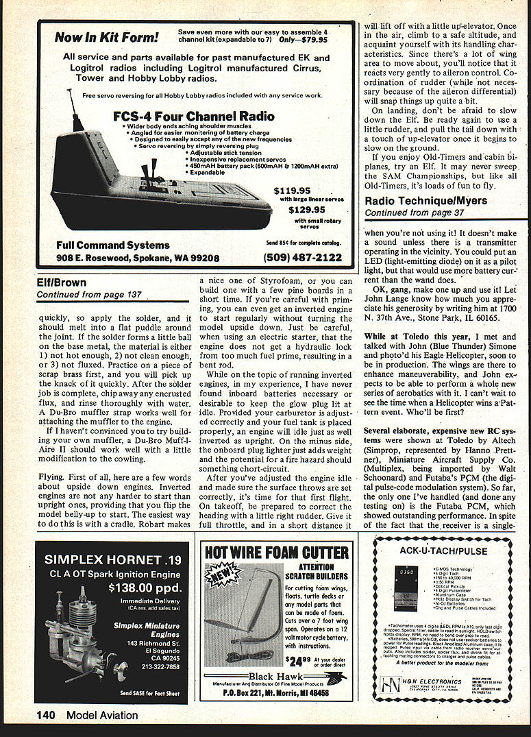
Struts
- Struts are optional (do not carry significant load) and should be built last after the model is finished.
- Measure finished wing gap or make a cardboard template to determine exact strut length; build to fit snugly.
- Note cross‑graining of balsa strut laminations before cutting — important for strength.
- Finish and epoxy paint struts to match cowl/wheel pants; epoxy mount 3/32" plywood blocks to each end of the struts and epoxy to the wings while aligned.
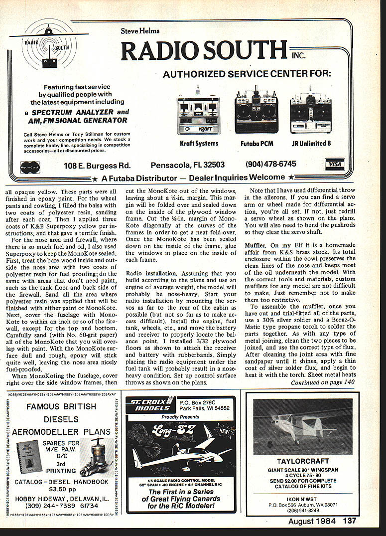
Tail Section
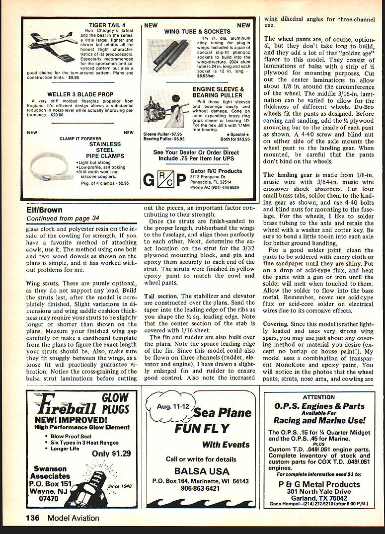
- Stabilizer and elevator built over the plans. Sand a taper into the leading edge of the ribs while shaping the 1/4" square leading edge. Center section of stab is sheeted with 1/16" balsa.
- Fin and rudder built over the plans — fin has a spruce leading edge. Slightly enlarged fin and rudder are shown for three‑channel use; increased wing dihedral figures for three‑channel flight are on the plans.
Wheel Pants
- Optional but quick to build and add period flavor. Laminate balsa with a strip of 1/4" plywood for mounting.
- Cut center laminations to allow about 1/8" clearance around the wheel; vary the middle 3/16" lamination for different wheel thicknesses.
- Add 1/4" plywood mounting bar inside each pant before carving. Mount with a 4‑40 screw and blind nut on either side of the axle. Ensure pants do not bind on the wheels.
- Finish pants with polyester resin and epoxy paint for durability and gloss.
Landing Gear
- Made from 1/8" music wire with 3/64" music wire crossover shock absorbers.
- Cut small brass tabs, solder to the landing gear, and mount with 4‑40 bolts and blind nuts to the fuselage.
- For axle: solder brass tubing to the axle and retain the wheel with a washer and cotter key. Bend a little toe‑in to each axle for better ground handling.
- For good solder joints: clean parts with emery or fine sandpaper until shiny, use acid flux, heat parts and apply solder. (Do not use acid flux on electrical wiring.)
Covering and Finishing
- The model is lightly loaded and uses strong wing spars, so most covering methods will work (avoid burlap or house paint).
- The author used transparent MonoKote combined with epoxy paint:
- Wheel pants, struts, nose area and cowling were epoxy painted (all opaque yellow in the photos).
- For wheel pants: two coats polyester resin, sand, then three coats K&B Superpoxy yellow per instructions.
- Nose area and firewall: fuel‑proof with two coats of polyester resin on bare wood; do same for tank floor and back side of firewall.
- Cover fuselage with MonoKote to within about 1" of firewall (top & bottom excepted). Sand overlap area of MonoKote with 60‑grit to dull it so epoxy will bond.
- When MonoKoting window frames, cover right over the frame, cut out the window leaving a 1/4" margin, fold margin over and seal inside the plywood frame (diagonal cuts at curves for neat folds), then glue windows in place.
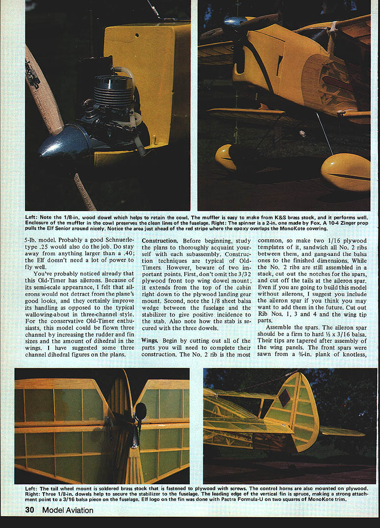
- Epoxy overlaps and fuel‑proofed areas are visible ahead of the red stripe in photos.
Radio Installation
- Mount servos as far rearward as possible (but still accessible).
- Install engine, tank, wheels, then move battery and receiver to set correct balance point; placing radio under tank often results in nose‑heavy condition.
- Use 3/32" plywood floors to attach receiver and battery with rubberbands.
- Set control throws per plans; use aileron differential (more up than down). If no differential wheel is available, redrill servo wheel as shown on plans and bend pushrods to clear servo shaft.
Muffler
- The author made a homemade muffler from K&S brass stock and enclosed it within the cowl to preserve clean lines and keep oil underneath the model.
- Construction tips:
- Trial‑fit all parts, then silver solder with 30% silver solder and a propane torch; use correct flux.
- Heat part evenly, avoid blackening inside of muffler and avoid overheating (brass warps).
- File and polish after cooling.
- Alternative: a Du‑Bro Muffl‑Aire II can work with minor cowling modifications.
Flying
- Inverted engines: not harder to start than upright ones if you flip the model belly‑up to start (use a cradle). Be cautious with priming and electric starters to avoid hydraulic lock.
- Inboard plug lighters add weight and fire risk; with correct carburetor adjustment and tank placement an inverted engine idles as well as upright.
- First flight procedure:
- Adjust engine idle and verify surface throws.
- On takeoff be prepared for a bit of right rudder; give full throttle and a little up elevator for liftoff.
- Climb to safe altitude and evaluate handling. The large wing area yields gentle aileron response; coordinate rudder for crisp moves.
- On landing slow the Elf and be ready to use a little rudder and a touch of up elevator to pull the tail down once it slows on the ground.
- If flown three‑channel (conservative Old‑Timer style), increase rudder/fin sizes and dihedral as noted on the plans.
If you enjoy Old‑Timers and cabin biplanes, try an Elf. It may never sweep the SAM Championships, but like all Old‑Timers, it's loads of fun to build and fly.
Transcribed from original scans by AI. Minor OCR errors may remain.

