
ELIMINATOR II
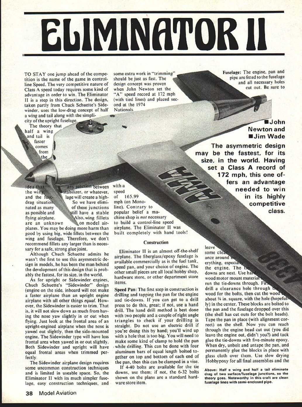
TO STAY one jump ahead of the competition is the name of the game in control-line Speed. The very competitive nature of Class A speed today requires some kind of advantage in order to win. The Eliminator II is a step in this direction. The design, taken partly from Chuck Schuette's Sidewinder, uses the low-drag concept of half a wing and tail along with the simplicity of the upright fuselage.
The theory that half a wing and tail is faster comes from the idea that any junction between the wing and the fuselage, stabilizer, or whatever, will create a high-drag situation. So we have eliminated as many of these junctions as possible and still have a stable flying airplane. Also, wing fillets are an unknown on model airplanes. You may be doing more harm than good by using big, wide fillets between the wing and fuselage. Therefore, we don't recommend fillets any larger than is necessary for a safe, strong glue joint.
Although Chuck Schuette admits he wasn't the first to use this asymmetric design in models, he has been the man behind the development of this design that is probably the fastest, for its size, in the world.
As for upright or Sidewinder engines, Chuck Schuette's "Sidewinder" design (engine on the side, inboard) will not make a faster airplane than an upright engine airplane with all other things equal. However, the Sidewinder is easier to trim. That is, it will not slow down as much from having the nose yaw slightly in or out when flying. Just look at the frontal area of an upright-engined airplane when the nose is yawed out slightly, then the side-mounted engine. The Sidewinder type will have less frontal area when yawed in or out slightly. Both Sidewinder and upright will have equal frontal areas when trimmed perfectly.
The Sidewinder airplane design requires some uncommon construction techniques and is limited in useable space. So, the Eliminator II with its much simpler fuselage, easy construction techniques, and some extra work in "trimming" should be just as fast. The design concept was proven when John Newton set the "A" speed record at 172 mph (with tied lines) and placed second at the 1974 Nationals with a speed of 165.99 mph (on Monoline). Contrary to popular belief a machine shop is not necessary to build a control-line speed airplane. The Eliminator II was built completely with hand tools!
Construction
Eliminator II is an almost off-the-shelf airplane. The fiberglass/epoxy fuselage is available commercially as is the fuel tank, speed pan, and your choice of engine. The other small pieces are all local hobby shop, hardware store, or other department store items.
Speed Pan
The first step in construction is drilling and tapping the pan for the engine and tie-downs. If you can get to a drill press to do this, great; if not, use a hand drill. The hand drill method is best done with two people and a couple of right angle triangles to check if your drilling is straight. Do not use an electric drill if you're doing this by hand; you'll wind up with a hole that is too big. You will need to make some kind of clamp to hold the pan while drilling. This can be done with four aluminum bars of equal length bolted together on top and bottom of each end of the pan, then this can be clamped in a vise.
If 4-40 bolts are available for the tie downs, use them; if not, the 6-32 bolts shown on the plans are a standard hardware store item.
Fuselage: The engine, pan and pipe are fitted to the fuselage and all necessary holes cut out. Be sure to leave some clearance around everything, especially the engine. The tie downs are next. Use hard wood motor mount material and run the tie-downs through. First drill a clearance hole through the wood for the bolts, then cut the wood about 1/4 in. square, with the hole (hopefully) in the center. These blocks are bolted to the pan and the fuselage dropped over this (the shell has cut outs for the bolt heads). Tape the pan in place (with alignment correct) on the shell. Now you can reach through the engine head cut out (you did leave the engine out, didn't you?) and tack glue the tie-downs with five-minute epoxy. When dry, unbolt and untape the pan, and permanently glue the blocks in place with glass cloth over them. Use slow drying Hobbypoxy for all final assemblies. Above: Half-wing, half-tail eliminate drag — two surface/fuselage junctions, the theory goes.
Noteworthy craft: clean fuselage lines, semi-enclosed pipe.
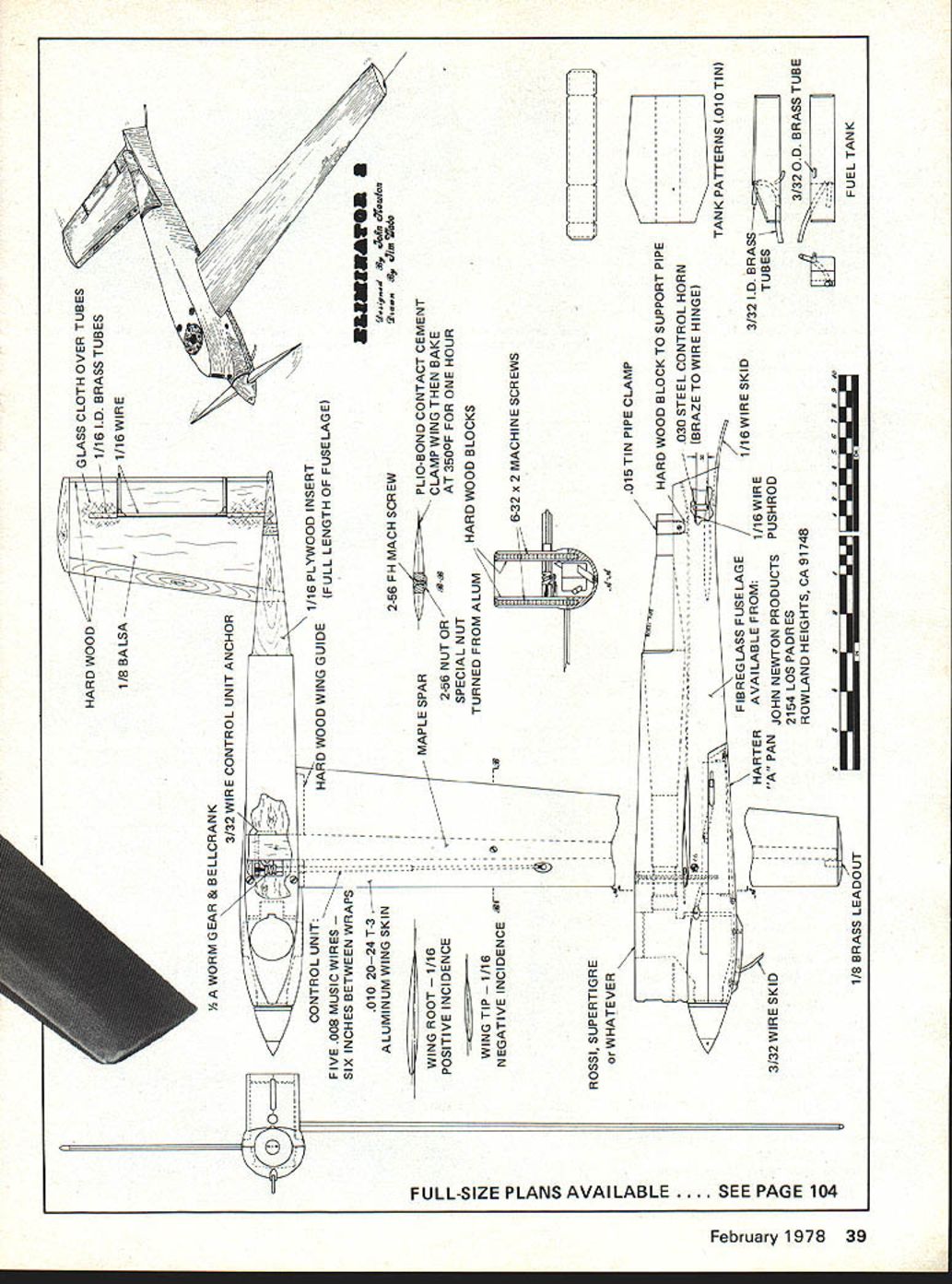
GLASS CLOTH OVER TUBES 1/16 I.D. BRASS TUBES 1/16 WIRE HARD WOOD 1/8 BALSA CONTROL UNIT ANCHOR HARD WOOD WING GUIDE 1/16 PLYWOOD INSERT (FULL LENGTH OF FUSELAGE) MAPLE SPAR ALUMINUM WING SKIN WING ROOT — 1/16 POSITIVE INCIDENCE WING TIP — 1/16 NEGATIVE INCIDENCE ROSSI SUPERTIGRE OR WHATEVER 3/32 WIRE SKID 1/16 WIRE PUSHROD .015 TIN PIPE CLAMP HARD WOOD BLOCK TO SUPPORT PIPE TANK PATTERNS 3/32 O.D. BRASS TUBE FUEL TANK FIBREGLASS FUSELAGE HARTER "A" PAN AVAILABLE FROM JOHN NEWTON PRODUCTS 1/8 BRASS LEADOUT
FULL-SIZE PLANS AVAILABLE .... SEE PAGE 104 five-minute kind for all tack glueing.
The rear of the pan is waxed and re-bolted on the shell, then run some epoxy down the rear of the pan to form a "key" to hold the rear of the pan in alignment. A couple of keys at the front of the pan might be helpful, but are not absolutely necessary.
Make the cut outs for the wing spar and tail. Also, split the rear top of the fuselage down to the stabilizer cut out.
Don't forget to cut out the 1/16 in. plywood inserts for the fuselage. These inserts strengthen the fuselage and keep hot air (from around the pipe) from entering the engine intake. Coat these with glue before inserting in the fuselage.
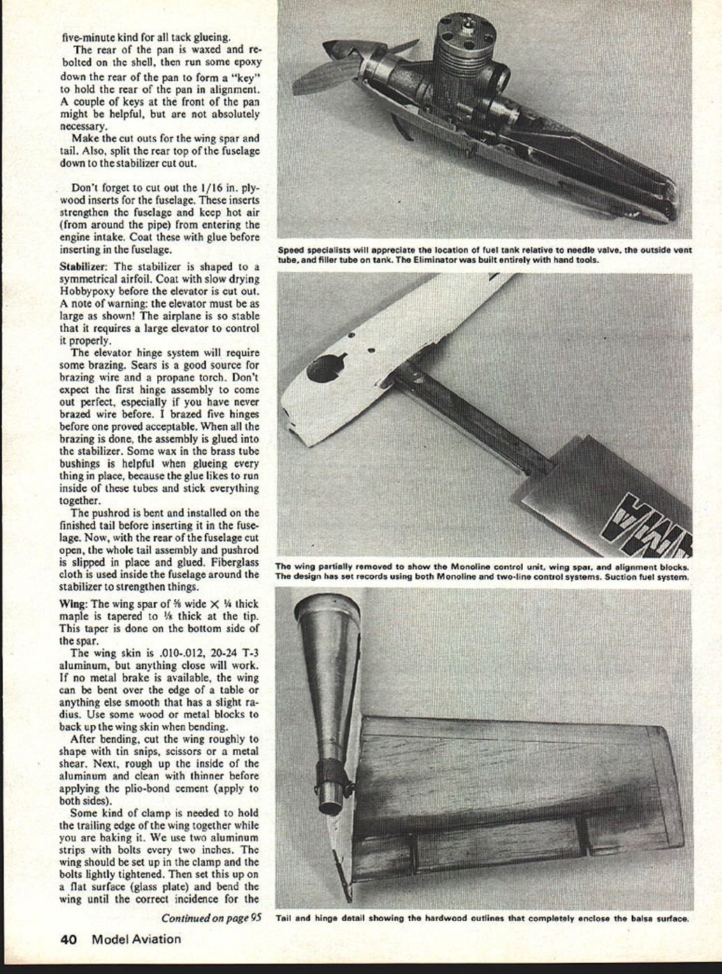
Stabilizer: The stabilizer is shaped to a symmetrical airfoil. Coat with slow drying Hobbypoxy before the elevator is cut out. A note of warning: the elevator must be as large as shown! The airplane is so stable that it requires a large elevator to control it properly.
The elevator hinge system will require some brazing. Sears is a good source for brazing wire and a propane torch. Don't expect the first hinge assembly to come out perfect, especially if you have never brazed wire before. I brazed five hinges before one proved acceptable. When all the brazing is done, the assembly is glued into the stabilizer. Some wax in the brass tube bushings is helpful when glueing everything in place, because the glue likes to run inside of these tubes and stick everything together.
The pushrod is bent and installed on the finished tail before inserting it in the fuselage. Now, with the rear of the fuselage cut open, the whole tail assembly and pushrod is slipped in place and glued. Fiberglass cloth is used inside the fuselage around the stabilizer to strengthen things.
Wing: The wing spar of 5/8 wide X 1/4 thick maple is tapered to 1/8 thick at the tip. This taper is done on the bottom side of the spar.
The wing skin is .010-.012, 20-24 T-3 aluminum, but anything close will work. If no metal brake is available, the wing can be bent over the edge of a table or anything else smooth that has a slight radius. Use some wood or metal blocks to back up the wing skin when bending.
After bending, cut the wing roughly to shape with tin snips, scissors or a metal shear. Next, rough up the inside of the aluminum and clean with thinner before applying the plio-bond cement (apply to both sides).
Some kind of clamp is needed to hold the trailing edge of the wing together while you are baking it. We use two aluminum strips with bolts every two inches. The wing should be set up in the clamp and the bolts lightly tightened. Then set this up on a flat surface (glass plate) and bend the wing until the correct incidence for the root and tip is achieved. Use a small steel scale marked in hundredths of an inch (.01) to check the alignment. The tip is 1/16 in. negative. The root should be 1/16 in. positive. When the alignment is correct, tighten the bolts and re-check the alignment, then bake for the required time. After the glue is baked and has cooled, the trailing edge is filed smooth and straight.
Control Units
Although a Mono-line unit is shown on the plans we will not go into detail on its construction because parts are not readily available. If you have built a similar control unit before and can find parts, the numbers are on the plans. A two-line system can be substituted very successfully for the Mono-line control unit. In fact, that was one of the reasons for originally designing and building the Eliminator II—so we could fly two lines and still be competitive with Mono-line.
Final Assembly Notes
Set up everything on a glass plate and measure before final assembly to ensure perfect alignment with the thrust line.
Some tooth picks might be helpful when aligning the spar and stab. Drill some 1/16 holes in the outboard side of the shell (where the spar will butt against) and in the spar, then use the toothpicks to align and hold the spar. Do the same for the stabilizer.
Use glass cloth around the spar for added strength (several layers of glass cloth).
We do not paint the tails of any of our airplanes because of the weight build up and the possibility of warping. The tail surface is sealed with epoxy glue rubbed into the wood (as are all unpainted wood surfaces).
Fuel Tank: The suction fuel system is very simple and should provide very constant engine runs. The tank itself can be easily made from .010 tin, or can be ordered from John Newton Speed And Racing Products, completely assembled and ready to bolt into the airplane.
Takeoff Dolly: Any three-wheel dolly with a front wheel spread close to the wing span should prove satisfactory. Ours is the lift-out type with two guide pins extending two to three inches above the wing—one at mid-wing, the other close to the fuselage. Some weight might be needed close to the outboard wheel; it just depends on the dolly design.
Engines, Fuel, Props: We use essentially stock Rossi Rear Rotor 15's. Except for a bar stock head, the engine is stock. We use a bar-stock head to save on the price of Rossi inserts. The Rossi insert is faster, if you can keep the element in for a whole run.
A stock Rossi with a stock 6-7 Rev-Up prop on 65% nitro can very consistently put you in the 162-mph bracket. With more nitro and the Rossi pipe as short as it will go, the 170 mph range is achievable, but not consistently.
The standard fuel mix used is usually 65-75% nitro, 20% oils, and the rest alcohol. We have always used at least 5%-10% castor oil in our fuel with the other oil content being a synthetic oil.
The Rev-Up 6-7 prop seems about right with the 65-75% nitro fuel and most weather conditions, but don't stop there. Experiment.
Flying: The airplane is very smooth flying and should present no real problems. On the takeoff run, hold some down elevator until flying speed is approached, then ease to neutral and the airplane should lift off easily. Don't let the airplane climb too high. Keep at about 5 feet.
If you have any questions or problems feel free to contact us: John Newton, 2154 Los Padres, Rowland Heights, CA 91748; Jim Wade, 1853 Yettford Rd., Vista, CA 92083.
Transcribed from original scans by AI. Minor OCR errors may remain.

