
The Engine Shop
Joe Wagner
Why small model engines seem expensive
A query that comes up from time to time goes something like this:
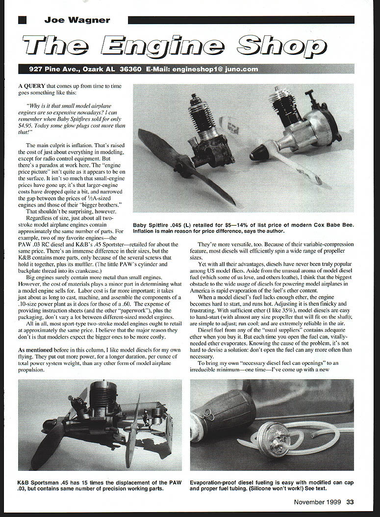
"Why is it that small model airplane engines are so expensive nowadays? I can remember when Baby Spitfires sold for only $4.95. Today some glow plugs cost more than that!"
The main culprit is inflation. That's raised the cost of just about everything in modeling, except for radio-control equipment. But there's a paradox: the "engine price picture" isn't quite as it appears. It isn't so much that small-engine prices have gone up; it's that larger-engine costs have dropped, narrowing the gap between the prices of 1/2A-sized engines and those of their bigger brothers. That shouldn't be surprising.
Regardless of size, just about all two-stroke model airplane engines contain approximately the same number of parts. For example, two of my favorite engines—the PAW .03 RC diesel and K&B's .45 Sportster—retailed for about the same price. There's an immense difference in their sizes, but the K&B contains only a few more parts, because of the several screws that hold it together and its muffler. (The little PAW's cylinder and backplate thread into its crankcase.)
Big engines surely contain more metal than small engines. However, the cost of materials plays a minor part in determining what a model engine sells for. Labor cost is far more important: it takes just about as long to cast, machine, and assemble the components of a .10-size power plant as it does for those of a .60. The expense of providing instruction sheets (and the other paperwork), plus the packaging, don't vary a lot between different-sized model engines.
All in all, most sport-type two-stroke model engines ought to retail at approximately the same price. I believe the major reason they don't is that modelers expect the bigger ones to be more costly.
Diesels: advantages and the ether-evaporation problem
As mentioned before in this column, I like model diesels for my own flying. They put out more power, for a longer duration, per ounce of total power-system weight, than any other form of model-airplane propulsion.
They're more versatile, too. Because of their variable-compression feature, most diesels will efficiently spin a wide range of propeller sizes.
Yet with all their advantages, diesels have never been truly popular among U.S. model fliers. Aside from the unusual aroma of model diesel fuel (which some of us love and others loathe), I think the biggest obstacle to wider use of diesels in America is rapid evaporation of the fuel's ether content.
When a model diesel's fuel lacks enough ether, the engine becomes hard to start and runs hot. Adjusting it is finicky and frustrating. With sufficient ether (I like 35%), model diesels are easy to hand-start (with almost any size propeller that will fit on the shaft), are simple to adjust, run cool, and are extremely reliable in the air.
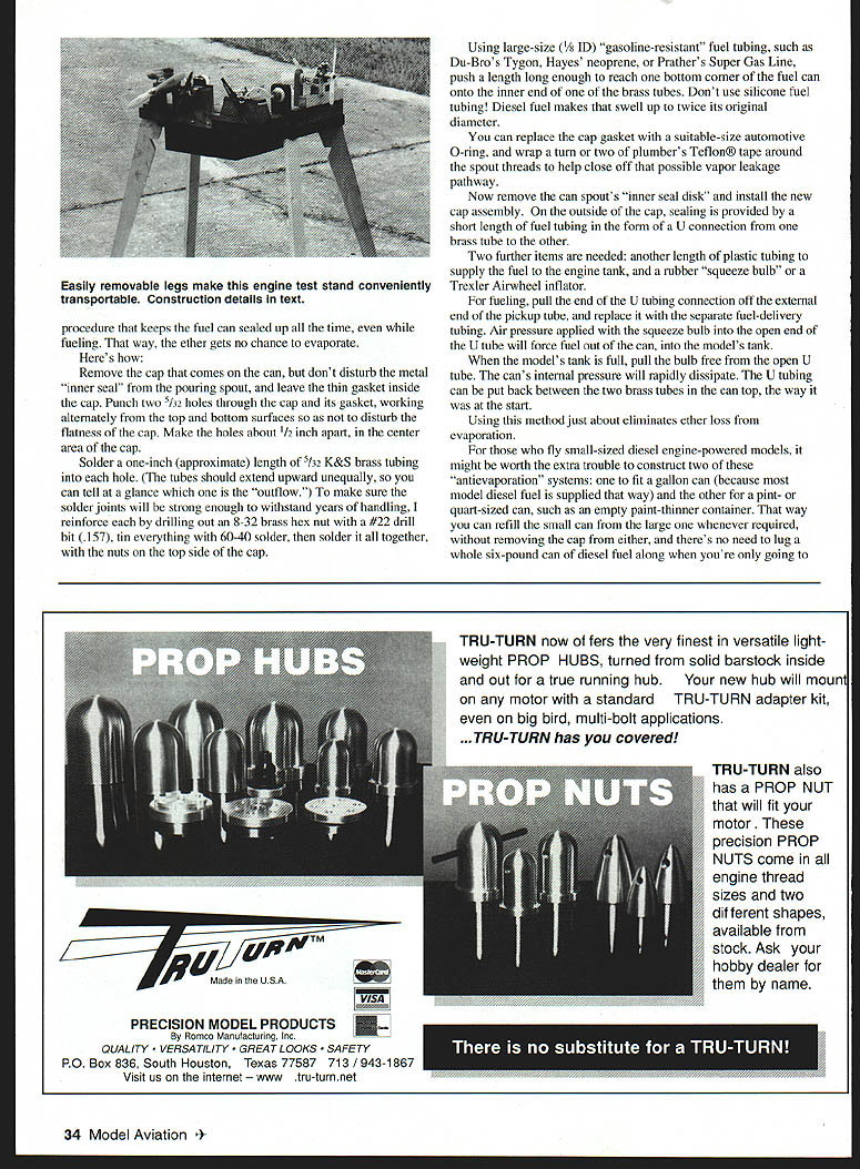
Diesel fuel from any of the usual suppliers contains adequate ether when you buy it. But each time you open the fuel can, vitally needed ether evaporates. Knowing the cause of the problem, it's not hard to devise a solution: don't open the fuel can any more often than necessary.
An evaporation-proof diesel-fueling method
To bring my own "necessary diesel fuel can openings" to an irreducible minimum—one time—I devised an evaporation-proof diesel-fueling method that keeps the fuel can sealed after that single opening. Here's how to make one:
- Remove the cap from the can, but don't disturb the metal inner seal (the pouring spout). Leave the thin gasket inside the cap.
- Punch two 1/32-inch holes through the cap and its gasket, working alternately on the top and bottom surfaces so as not to disturb the flatness of the cap. Make the holes about 1/2 inch apart in the center area of the cap.
- Solder one-inch lengths of 1/32 K & S brass tubing into the holes; the tubes should extend upward unequally so you can tell at a glance which is the outflow. Make sure the solder joints are strong enough to withstand years of handling.
- Reinforce by soldering an 8-32 brass hex nut to the top side of the cap (drill the nut out with a #22 drill bit first). Tin everything with 60-40 solder, then solder the nut and tubes to the top side of the cap.
- Using large-size 3/8-inch ID gasoline-resistant fuel tubing (such as Du-Bro Tygon, Hayes neoprene, or Prather's Super Gas Line), push a length long enough to reach the bottom corner of the fuel can onto the inner ends of the brass tubes.
- Do not use silicone fuel tubing—diesel fuel makes it swell up to twice its original diameter.
- You can replace the cap gasket with a suitable-size automotive O-ring. Wrap two turns of plumber's Teflon tape around the spout threads to help close off any possible vapor-leakage pathway.
- Remove the can spout's inner seal disk and install the new cap assembly; the outside cap sealing is provided by the short length of fuel tubing formed into a U connection between the two brass tubes.
Two further items are needed:
- Another length of plastic tubing to supply fuel to the engine tank.
- A rubber squeeze bulb or a Trexler Airwheel inflator.
For fueling:
- Pull the end of the U tubing connection off the external end of the pickup tube, and replace it with the separate fuel-delivery tubing.
- Apply air pressure with the squeeze bulb into the open end of the U tube; this forces fuel out of the can into the model's tank.
- When the model's tank is full, pull the bulb free from the open U tube. The can's internal pressure will rapidly dissipate. Put the U tubing back between the two brass tubes in the can top the way it was at the start.
Using this method just about eliminates ether loss from evaporation.
For those who fly small diesel-powered models, it might be worth the extra trouble to construct two of these antievaporation systems: one to fit a gallon can (because most model-diesel fuel is supplied that way) and the other for a pint- or quart-sized can, such as an empty paint-thinner container. That way you can refill the small can from the large one whenever required without removing the cap from either, and there's no need to lug a whole six-pound can of diesel fuel when you're only going to the local field to fly your .06-powered airplane.
Breaking in engines: why use a test stand
I feel it's always better to break in a new model engine on a test stand rather than in an airplane. The test stand gives you easy access to everything; and since the new engine is out in the open, it receives maximum cooling just when it needs it most.
However, quite a few fliers avoid model engine test stands, claiming they're inconvenient to use:
"If you bolt one of those to your workbench to break in your engines indoors, oil gets all over the place, the room fills with fumes, and there's way too much racket. But doing the job outside is just as bad. You can't make a really permanent installation because of the weather—and installing temporary outdoor engine test setups and then tearing them down later takes way too much time and trouble for me."
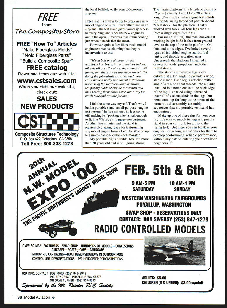
I felt the same way myself. That's why I built a portable stand: an all-purpose engine test system. In five minutes its legs come off, making its package size small enough to fit in a VW Bug's luggage compartment. Another five minutes and the stand is reassembled, ready for test-running any model engine from a Cox Pee Wee up to a more-than-one-cubic-inch monster.
My portable rig is durable, too—it's more than 30 years old and still going strong.
Portable engine test stand: construction and features
- Main platform: a length of clear 2 x 12 pine (actually 1 1/2 x 11 1/2), 28 inches long. Similar stands have been made using three-foot particle-board shelf stock with good results.
- Legs: all four legs cut from a single eight-foot 2 x 4.
- Working height: for me (5'6" tall) the convenient top-of-platform height is 32 inches from the ground.
- Attachments: several types of individual engine stands, fuel tanks, and throttle-actuation arms are bolted to the platform edges.
- Storage: a drawer installed underneath the platform for tools, propellers, and other useful items.
- Leg mounting: removable legs splay outward at a 15° angle for a wide, stable stance. Each leg is attached with a single 3/8 x 4 bolt that threads into a T-nut installed in a notch cut into the back edge of the leg.
- Note: threaded inserts of various kinds were tried but didn't withstand the stress of repeated disassembly and assembly.
Make up one of these rigs for your own use. It's easy to unbolt the legs and put the stand in your car trunk for a trip to the flying field. Out there you can break in your engines, for as long as it takes for them to develop cool-running, reliable performance, without any risk of irritating your next-door neighbors.
Transcribed from original scans by AI. Minor OCR errors may remain.

