


The Engine Shop
135 Waugh Avenue, New Wilmington PA 16142
Propeller-driven power: models vs full-scale aircraft
ANYTIME someone makes a snide remark to you about your "toy airplanes," you might squelch them with the fact that model aircraft are the highest-powered propeller-driven vehicles in existence. And that's not by any narrow margin, either!
Take the speediest and fastest-climbing prop-equipped fighter ever built: Grumman's F8F Bearcat. It weighed 9,334 pounds and had 2,800 horsepower—that's about 3 1/3 pounds per horsepower for the Navy fighter version. The recent world-record-setting, specially modified Rare Bear Bearcat came out to somewhere around two pounds per horsepower. That's a mighty impressive weight-to-power ratio—until you consider that today's competition Free Flight models nearly double it.
A typical .15-powered F1C Free Flight entry weighs 27 ounces, and its engine develops about 1.5 horsepower. That works out to a fantastic 1.10 lb/hp!
The reason for the incredible power levels in today's competition model airplane engines is that Free Flight (FF) has effectively become a racing event—the "race" is for maximum vertical distance in a given time. Competing in it requires much the same sort of powerplants as Control Line Speed.
The extraordinary power output of today's competition model airplane engines comes from:
- intensive design and development,
- the very latest metallurgical advances,
- high-nitro fuel, and
- rpm in the close-to-30,000 range.
Rule of thumb for prop-driven speed
A useful Rule of Thumb: the approximate maximum speed limit (in mph) of a propeller-driven airplane equals the propeller pitch (in inches) times the engine rpm (in thousands). Thus a CL Stunt model pulled by a 9 x 5 prop spinning 10,000 rpm just can't travel more than about 50 mph.
If you want speed there are two ways to get it:
- use a higher-pitch prop,
- increase rpm—preferably both.
Notice the horsepower the engine develops doesn't enter directly into this relationship. You could have a four-horsepower chain‑saw engine on a model driving an eight-inch-pitch prop; regardless of its diameter, at 9,000 rpm the aircraft couldn't exceed about 72 mph in a full-throttle dive. That's the reason today's 30,000+ rpm model engines' performance astounds.
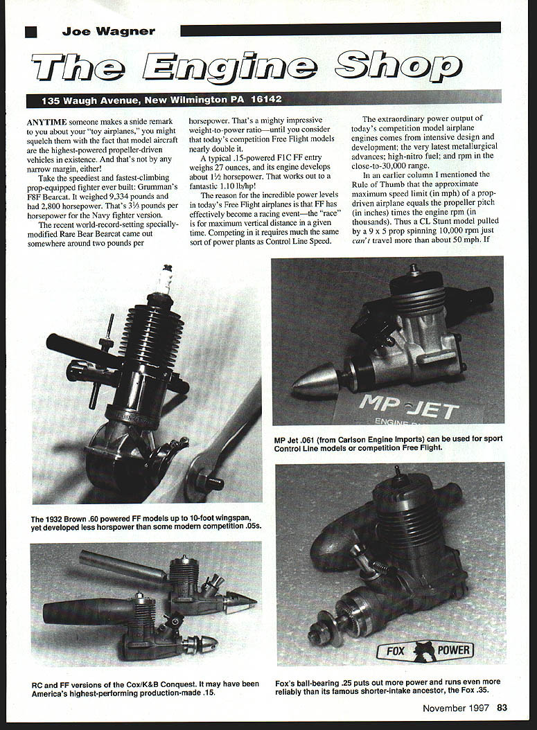
Their dynamometer figures are impressive: 1.80 hp from a Rossi .21; 0.26 hp from an MP Jet .061. Of course, those horsepower figures come from dyno testing and don't necessarily represent what happens in flight.
For example, take the Brown Junior .60 that powered Joe Konefes' Buzzard Bombshell on its 49-minute flight that won the Class C Free Flight at the 1941 Nationals. The Brown put out well under one-fifth horsepower that day. Any of the new Russian competition .11A glow engines can outdo that on paper, yet if you installed, say, an AME in the nose of Joe's famous record-setter, even at 30,000 rpm it could barely manage to taxi that six-foot, 3½-pound thick-winged craft. High rpm's not everything!
For most model flying, 15,000 rpm is plenty fast enough. That's what my MP Jet .061 delivers on 5% nitro fuel and an APC 7 x 3 prop—close-to-ideal power for small CL Stunt models.
Dangers of high rpm and prop choice
High rpm has dangers. When model engine speed doubles (for example, from 10,000 to 20,000 rpm) the forces tending to pull the prop apart increase dramatically—by a factor of sixteen in the examples discussed by experienced builders—so propeller hub stresses and centrifugal effects must be taken seriously.
True model propeller makers have beefed up their products. APC props have featured massive hubs right from the start; Windsor and Master Airscrew have strengthened theirs as well. Fliers who compete with engines that turn in the 30,000 rpm range would not even think of trying props with skimpy hubs. Those guys are pros, and they know better!
Still, there's always the fellow who loves to hear his engine shriek and may be tempted to put a plain nylon 7 x 4 on a honkin' Conquest .15 to see how fast it'll spin. That's tragedy in the making.
Customizing engines — what's worthwhile
Back in the Good Old Days a sizable number of us gas-model fliers put a fair amount of time and ingenuity into "hopping up" our engines. Most of that effort did little good; some of it did harm. Still, we felt we were accomplishing something worthwhile, even if it amounted mostly to "personalizing" our powerplants.
There's always been a temptation for mechanically minded people to customize automobiles, bikes, computers, boats, and model airplane engines. But with today's ever-increasing level of technology, it's getting harder to find affordable, do-it-yourself improvements that actually help.
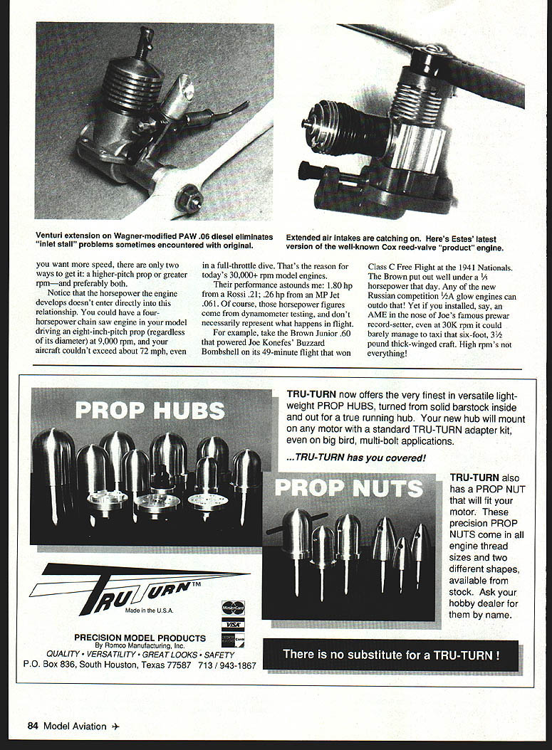
However, there is a relatively simple, highly beneficial modification you can make to most model airplane engines. It boosts reliability, usually adds power, and makes your engine look noticeably different from stock: extend the venturi (lengthen the air intake). That isn't a new idea; it's merely little-understood.
First investigated and reported on by prewar British model engine expert Col. C. E. Bowden, and later written about by E. C. "Ted" Martin, lengthened air intakes never caught on widely. For about 40 years I've been reworking and customizing model engines. In all that time the single most beneficial change I've ever found has been adding venturi extensions.
Doing that improves fuel draw. When combined with a smoothly contoured bellmouth air inlet, it boosts running reliability and adds power. Here's why.
Why venturi extensions and bellmouth inlets help
The inlet port of any model engine (two-stroke or four-stroke) is open for just part of each shaft revolution. That's the only time the air/fuel mixture can enter. For that reason, the flow through the entry port pulsates.
Pulsating airflow in a model engine's intake is detrimental because it takes time for the flow to get started and up to speed. Just when the incoming air/fuel flow gets moving nicely into the engine, its inlet closes and cuts the inflow off. The air/fuel mix approaching the inlet port at that instant "bounces back." It's moving the wrong way as the inlet port reopens and has to reverse again. That takes time.
Airflow that oscillates at the inlet port costs power. It limits the amount of oxygen the engine can "inhale" to burn its fuel. As for fuel supply by suction, you could hardly ask for worse conditions for delivering consistent, reliable fuel flow than a pulsating vacuum at the spraybar orifice.
The only reason a suction-feed model engine can overcome this problem is that the airstream passing through its venturi has both momentum and compressibility. The inertia of the air accelerating inward through the venturi entry tends to keep it going, even though the flow at the engine end is stop-and-go. It does that by compressing the air ahead of it in the "passageway." But if the passageway is short, the amount of air within it at any given instant may not have enough "moving mass" to overcome the pulsation at the engine's inlet port.
Speeding up the flow increases momentum, which is why "model engines are happier at high rpm." If the passageway is long, there's enough air mass moving within it to keep the inflow steady even at low rpm. One reason today's RC engines idle so much more reliably than those of yesteryear is that their total inlet passage length is greater.
Inlet stall and the bellmouth analogy
There's also the mysterious "inlet stall" phenomenon. Ducted-fan fliers were among the first to notice the ill effects. When that branch of aeromodeling was new, experimenters found that the contour of a duct's entry had as much effect on airflow through it as its cross-sectional area. Sharply-edged duct entries stole power from the fans—especially when the airplane was turning and meeting the air at an angle. Fan fliers soon discovered that smoothly radiused "bellmouth" duct entries boosted airflow, raised efficiency, and eliminated much of the sensitivity to sidewash airflow.
A useful analogy: imagine a crowd tossing Ping-Pong balls as rapidly as possible at a bottomless coffee can on the floor. Balls that go into the can fall through; those that miss do nothing. Balls that strike the rim or the area just inside it will bounce and interfere with other incoming balls, preventing some from entering. This interference becomes worse when the balls are thrown at an angle to the can's axis. The jam-up at the entry is like inlet stall.
To make it easy for the "balls" (air molecules) to pass through an opening, the opening should be trumpet-shaped with a gently rounded edge. Those molecules that hit the wall surfaces on the way in will be deflected only slightly from their entry path, and no obstructive jam-up will clog the inflow.
What happens at a model airplane engine's air inlet has a major effect on its performance. Its power depends on an optimum fuel-air mixture reaching the combustion chamber—but that has to pass through the intake passage first. (True, some air can enter via subpiston induction—Cox Tee Dees use that feature—but the subpiston gap is narrow and remains open exceedingly briefly: less than half a millisecond for a TD .049 at 18,000 rpm. Not much air can sneak into the engine in that flicker of time.)
What I'll cover next
Do you know why rear-rotary induction was used on so many record-setting racing engines (e.g., McCoys and Doolings) instead of the far simpler front-rotary valve? Or why restricting intake diameter often cures an erratic engine? How about why getting good midrange settings is such a trick to achieve with RC barrel throttles?
I'll explain all those points—and more—in my next column.
One practical tip
Keep a plastic bag (the type used in supermarkets for produce) wrapped around the nose of each of your engine-powered models any time it's not being flown. That simple step can add years to your engines' lifespan.
Transcribed from original scans by AI. Minor OCR errors may remain.

