

The Engine Shop
Joe Wagner
West Coast Park Flyer Fun-Fly
In October I attended the first West Coast Park Flyer Fun-Fly, sponsored by the Blacksheep club, at Robert Gross Park in Burbank, California. Naturally, electric-powered airplanes predominated, but a few CO2 radio control (RC) models were present—and their performance graphically demonstrated to everyone there the advantages of CO2 power over electric.
CO2 motors run just as quietly as electric, but their power systems weigh far less, and they can be recharged in a few seconds from carry-anywhere CO2 “bulk reservoirs” (such as flashlight-sized CO2 cylinders for paintball guns). As for in-flight motor speed control, many of Stefan Gasparin’s latest line of Czech-made CO2 motors include RC throttles.
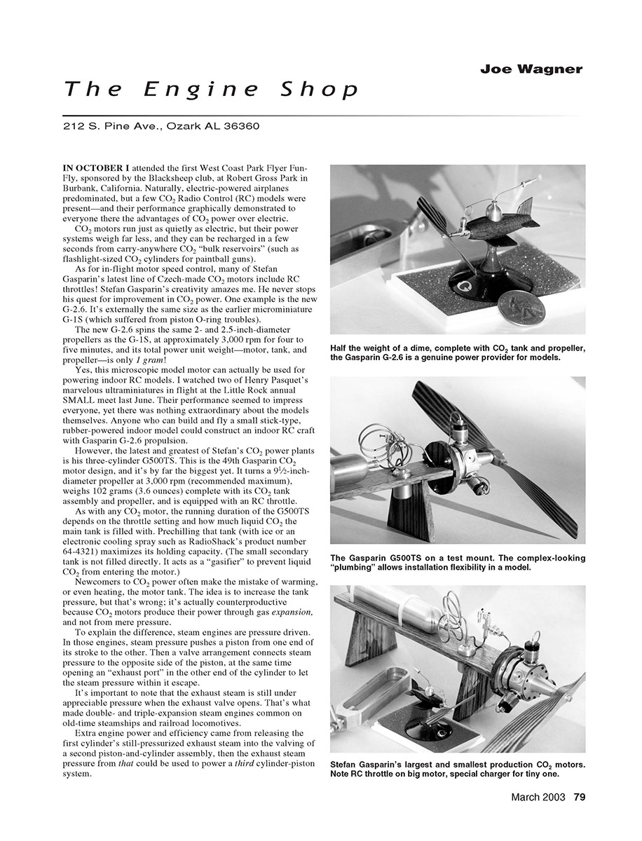
Stefan Gasparin’s creativity amazes me. He never stops his quest for improvement in CO2 power. One example is the new G-2.6. It’s externally the same size as the earlier microminiature G-1S (which suffered from piston O-ring troubles). The new G-2.6 spins the same 2- and 2.5-inch-diameter propellers as the G-1S at approximately 3,000 rpm for four to five minutes, and its total power unit weight—motor, tank, and propeller—is only 1 gram.
Yes, this microscopic model motor can actually be used for powering indoor RC models. I watched two of Henry Pasquet’s marvelous ultraminiatures in flight at the Little Rock annual SMALL meet last June. Their performance seemed to impress everyone, yet there was nothing extraordinary about the models themselves. Anyone who can build and fly a small stick-type, rubber-powered indoor model could construct an indoor RC craft with Gasparin G-2.6 propulsion.
The G500TS: Gasparin’s Largest CO2 Motor
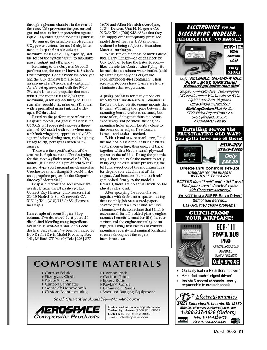
However, the latest and greatest of Stefan’s CO2 power plants is his three-cylinder G500TS. This is the 49th Gasparin CO2 motor design, and it’s by far the biggest yet. It turns a 9½-inch-diameter propeller at 3,000 rpm (recommended maximum), weighs 102 grams (3.6 ounces) complete with its CO2 tank assembly and propeller, and is equipped with an RC throttle.
As with any CO2 motor, the running duration of the G500TS depends on the throttle setting and how much liquid CO2 the main tank is filled with. Prechilling that tank (with ice or an electronic cooling spray such as RadioShack product number 64-4321) maximizes its holding capacity. (The small secondary tank is not filled directly; it acts as a “gasifier” to prevent liquid CO2 from entering the motor.)
Newcomers to CO2 power often make the mistake of warming, or even heating, the motor tank. The idea is to increase the tank pressure, but that’s wrong; it’s actually counterproductive because CO2 motors produce their power through gas expansion, not from mere pressure.
How CO2 Motors Work
To explain the difference, steam engines are pressure driven. In those engines, steam pressure pushes a piston from one end of its stroke to the other. Then a valve arrangement connects steam pressure to the opposite side of the piston while opening an exhaust port in the other end of the cylinder to let the steam within it escape. The exhaust steam is still under appreciable pressure when the exhaust valve opens. That’s what made double- and triple-expansion steam engines common on old-time steamships and railroad locomotives: extra engine power and efficiency came from releasing the first cylinder’s still-pressurized exhaust steam into the valving of a second piston-and-cylinder assembly, then using that exhaust steam pressure to power a third cylinder-piston system.
However, CO2 motors don't work that way. Their cylinders are supplied with high-pressure gas only briefly, at the very top of the piston’s stroke. As soon as that piston starts moving, the inlet valve closes and the CO2 inflow shuts off. From then on, gas expansion provides the power that moves the piston. Ideally, when the CO2 motor's exhaust ports open (which they do at the bottom of the stroke, just like those of a two-stroke internal-combustion engine), the gas in the cylinder has expanded almost to atmospheric pressure. That’s why CO2 motors run so quietly: very little energy is released through the exhaust ports and converted into noise.
Because CO2 motors do their work via gas expansion, the fins on their cylinders act as warming fins. As anyone who has felt the chilly outflow from a compressed-air gun knows, whenever pressurized gas is released through an orifice it absorbs heat as it expands. To maximize that expansion, more heat needs to be added from an external source. In CO2 motors, that source is the warmth of the surrounding air.
Stefan Gasparin's new three-cylinder G500TS seems especially efficient in transferring atmospheric heat to its cylinders. Its crankcase and finely finned cylinders provide ample surface area exposed to the propeller slipstream. In addition, the CO2 supply to the G500TS cylinders passes through a plenum chamber in the rear of the case. This prewarms the pressurized gas and further protects against liquid CO2 entering the motor's cylinders.
To sum up the principle: CO2 power systems for model airplanes need to keep their tanks cold (to maximize liquid CO2 capacity) and the rest of the system warm (to maximize power output and efficiency).
G500TS Performance and Application
The motor I have is Stefan’s first prototype. I don't know the price yet, and the CO2 tank system size and arrangement isn't necessarily optimized. As it’s set up now, and with the 9½ x 9½-inch laminated propeller that came with it, the motor runs at 2,700 rpm maximum, gradually declining to 1,000 rpm after roughly six minutes (that was with a prechilled main tank and wide-open RC throttle).
Based on the performance of earlier Gasparin motors, I'd guesstimate that the G500TS will adequately power a three-channel RC model with roughly a 40-inch wingspan, approximately 250 square inches of wing area, and weighing (ready to fly) perhaps as much as 22 ounces.
Those are the specifications of the semiscale airplane model I'm designing for this three-cylinder marvel of a CO2 motor. It’s based on a pre-World War II parasol-type sport monoplane designed in Czechoslovakia—a fitting project for the Gasparin three-cylinder radial.
Where to Buy
Gasparin motors and accessories are available from the Blacksheep club. Contact Roy Hanson (club treasurer) at:
- 21410 Nashville St., Chatsworth, CA 91311
- Tel.: (818) 718-1685 (leave a message)
Diesel Fuel, Suppliers, and Fuel Containers
In a couple of recent Engine Shop columns I've described do-it-yourself diesel-fuel blending using ingredients available at Wal-Mart and John Deere dealers. Since then I've been reminded by Bob Davis and Allen Heinrich that they can supply excellent-quality premixed model diesel fuel via UPS without Hazardous Material surcharges:
- Bob Davis — Davis Model Products, Box 141, Milford, CT 06460; Tel.: (203) 877-1670
- Allen Heinrich — Aerodyne, 17244 Darwin, Unit H, Hesperia, CA 92345; Tel.: (760) 948-6334
Larry Renger—chief engineer for Cox Hobbies before the Estes buyout—likes diesels for control-line flying. He learned that aluminum water bottles (sold by camping-supply dealers) make excellent model-fuel containers. Their screw-in stoppers have O-ring seals that eliminate ether evaporation.
Modifying Molded Plastic Engine Mounts
A pesky problem for many modelers who fly with smaller-size RC engines is finding molded plastic engine mounts that fit them. Widening the space between the mounting beams works sometimes, but more often that thins the beams excessively and positions the engine-mounting holes uncomfortably close to the beam outer edges. I’ve found a better—and easier—method:
- Cut the molded plastic mount in half on its vertical centerline with a band saw or scroll saw.
- Insert a birch aircraft-plywood spacer in the middle and epoxy the halves back together. This allows fitting the mount exactly to the engine case while preserving the full cross-section of the mounting lugs for dependable attachment.
- Do the assembly on a waxed-paper-covered flat surface to ensure accurate alignment.
- After epoxying, carefully sand or file the rear surface and the engine-mounting beam tops flat. This ensures maximum mounting security and minimal localized stresses throughout the engine installation.
Because the mount itself is bolted firmly to the model's firewall, there are no significant loads on the glued center joint.
JW
Transcribed from original scans by AI. Minor OCR errors may remain.

