
The Engine Shop
Air density and engine performance
Performance of any internal combustion engine depends on how much oxygen it can inhale to burn fuel. It needs plenty. Air contains about 21% oxygen, and for every cubic inch of fuel/oil vapor that enters a glow model engine's inlet, roughly seven cubic inches of air are required for complete combustion. (Diesels and gasoline-fueled engines need about 12 cubic inches of air.)
Those numbers are for "standard conditions," but conditions vary considerably, especially when model airplanes are being flown. Engines lose power in hot weather (the air is less dense) and with increasing altitude. Humidity also causes power loss: whenever water vapor is present in the atmosphere, it displaces some of the oxygen by volume. (Moist air's density is lower, which is one reason it tends to rise and form clouds.) Low barometric pressure (from an impending weather change) also lowers air density.
These effects are combined in full-scale aviation into a number called "density altitude," which varies with local conditions. You can find the density altitude where you are by calling your local airport.
Density altitude and power loss (example)
As I write this (July 14, 4 p.m.), the air temperature here (near Pittsburgh, PA) is 83° Fahrenheit, and my hygrometer (by no means a precision instrument) indicates about 80% humidity. The airport is located 860 feet above mean sea level (MSL); however, with the temperature and humidity as high as they are, the density altitude at the airport is about 2,200 feet.
That means that, for example, if you were flying a Cessna 172 from here this afternoon, you'd have to restrict its gross weight to what it could safely take off with from an airport 2,200 feet above sea level in standard conditions. To a model flier, a density altitude of 2,200 feet means your engine will only be able to put out about 94% of the power it could at sea level. Propeller thrust and wing lift will suffer similar reductions.
To calculate percentage power available:
- Subtract the density altitude in thousands of feet from 36.
- Divide that result by 36.
Example with density altitude 2,200 feet:
- 36 − 2.2 = 33.8
- 33.8 ÷ 36 = 0.94 → 94%
Turbulence and intake location
There is one more variable that can reduce the density of the air your engine breathes: turbulence. Bernoulli's Principle states that a fluid's static pressure drops when that fluid is in motion. Air is a fluid, and turbulent air, by definition, is highly in motion, which reduces its effective density—more than you might suspect.
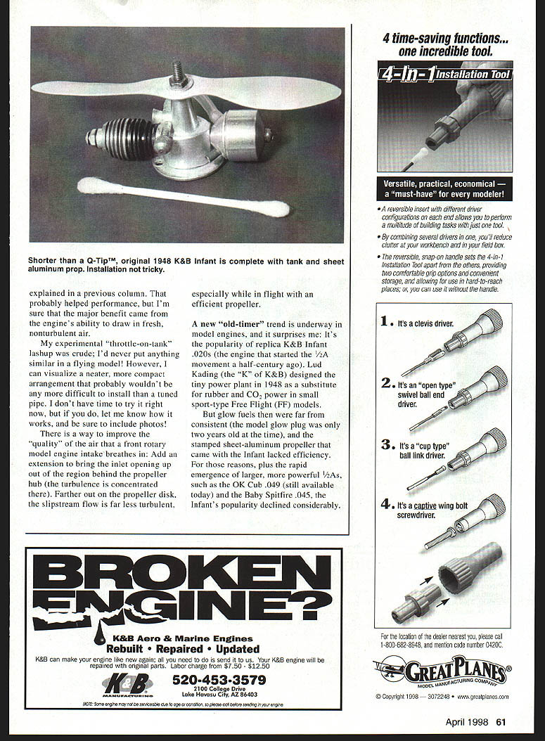
When a model's engine is running, the air behind its whirling propeller hub becomes exceedingly turbulent (even with a spinner). That turbulent air is what "front rotary" model airplane engines are compelled to breathe for combustion.
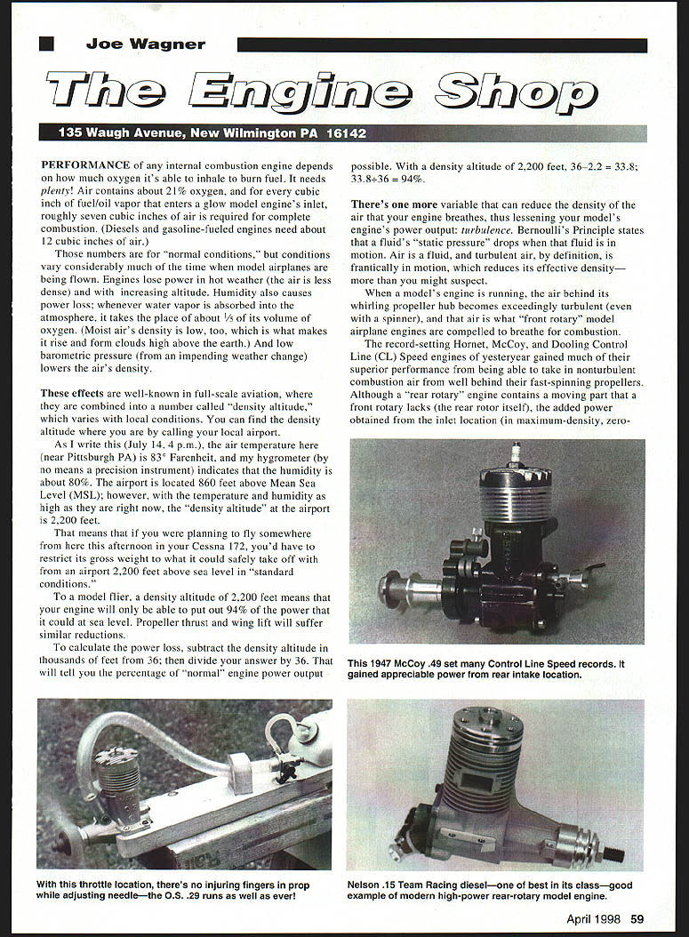
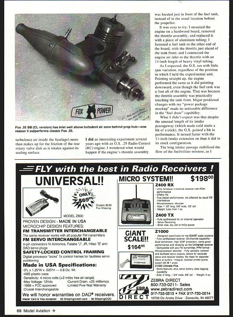
Record-setting Hornet, McCoy, and Dooling control-line speed engines of yesteryear gained much of their superior performance from being able to take in nonturbulent combustion air from well behind their fast-spinning propellers. Although a "rear rotary" engine contains a moving part that a front rotary lacks (the rear rotor itself), the added power obtained from the inlet location—in maximum-density, near-zero-turbulence air—is significant. Turbulence (for example, air inside the fuselage) more than makes up for the friction of a rear rotary valve disk as it rotates against its sealing surface, especially while in flight with an efficient propeller.
Intake-extension experiment (O.S. .29)
Several years ago I did an experiment with an O.S. .29 radio-control engine. I wondered what would happen if the engine's throttle assembly were located just in front of the fuel tank instead of the usual location behind the propeller. It was an easy try: I mounted the engine on a hardwood board, removed the throttle assembly, and replaced it with a short piece of aluminum tubing fastened to the fuel tank at the other end of the board. The throttle was just ahead of the tank front and was connected to the engine air inlet by an 11-inch length of heavy vinyl tubing.
As expected, the O.S. ran with little rpm variation regardless of the position in which the experimental unit was held. Pointing straight up, the engine performed the same as when pointing downward, even though the fuel tank was a foot aft of the engine, because the throttle assembly was practically touching the front of the tank. Major positional changes to the power-package mockup made no noticeable difference in fuel-draw capability.
What I didn't expect was that cold starts were a bit trickier, despite the unusual length of the intake passageway. The O.S. .29 did gain a bit of performance — it turned faster. The 11-inch intake extension, like the stock configuration, stabilized the flow of the fuel/oil/air mixture.
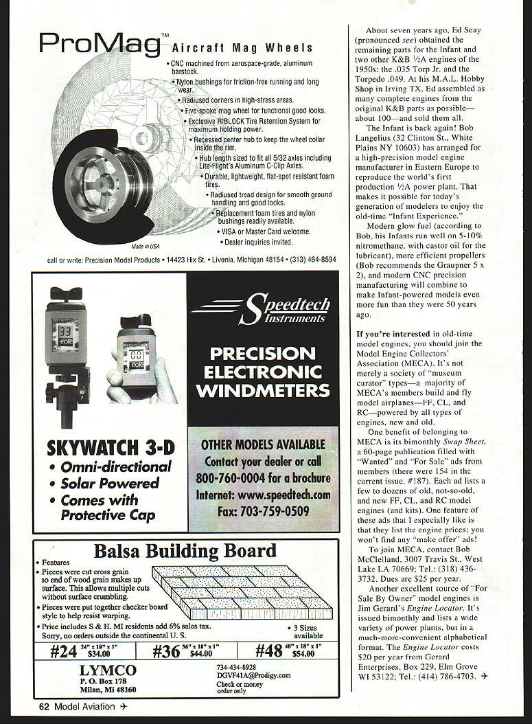
Replica K&B Infant .020 and "old-timer" trend
A new "old-timer" trend is underway in model engines: the popularity of replica K&B Infant .020s, the engine that helped start the 1/2A movement a half-century ago. Lud Kading (the "K" of K&B) designed the tiny power plant in 1948 as a substitute for rubber and CO2 power in small sport-type free-flight models.
At the time, glow fuels were far from consistent (the model glow plug was only two years old), and the stamped sheet-aluminum propeller that came with the Infant lacked efficiency. For those reasons, and because larger, more powerful 1/2As such as the OK Cub .049 and the Baby Spitfire .045 emerged quickly, the Infant's popularity declined.
About seven years ago Ed Seay (pronounced "see") obtained the remaining parts for the Infant and two other K&B 1/2A engines of the 1950s: the .035 Torp Jr. and the Torpedo .049. At his M.A.L. Hobby Shop in Irving, TX, Ed assembled as many complete engines from the original K&B parts as possible—about 100—and sold them all.
Now the Infant is back. Bob Langeluis (32 Clinton St., White Plains, NY 10603) has arranged for a high-precision model engine manufacturer in Eastern Europe to reproduce the world's first production 1/2A power plant. Modern glow fuel (Bob reports his Infants run well on 5–10% nitromethane, with castor oil as the lubricant), more efficient propellers (Bob recommends the Graupner 5 × 2), and modern CNC precision manufacturing will combine to make Infant-powered models even more fun than they were 50 years ago.
Model Engine Collectors' Association (MECA) and resources
If you're interested in old-time model engines, consider joining the Model Engine Collectors' Association (MECA). It's not merely a society of "museum curator" types—a majority of MECA members build and fly model airplanes (free flight, control line, and radio control) powered by all types of engines, new and old.
One benefit of MECA membership is its bimonthly Swap Sheet, a 60-page publication filled with "Wanted" and "For Sale" ads from members (there were 154 ads in the current issue, #187). Each ad lists a few to dozens of old, not-so-old, and new free-flight, control-line, and radio-control model engines (and kits). A feature I especially like is that the ads list engine prices; you won't find "make offer" ads.
To join MECA:
- Contact: Bob McClelland, 3007 Travis St., West Lake, LA 70669
- Tel.: (318) 436-3732
- Dues: $25 per year
Another excellent source of "For Sale By Owner" model engines is Jim Gerard's Engine Locator. It's issued bimonthly and lists a wide variety of power plants in a convenient alphabetical format.
- Cost: $20 per year
- Order from: Gerard Enterprises, Box 229, Elm Grove, WI 53122
- Tel.: (414) 786-4703
Transcribed from original scans by AI. Minor OCR errors may remain.

