
The Engine Shop
Several readers asked for more specifics about the engine intake extensions mentioned in a previous column: "How long?" "What's the best length?" "Where can you buy them?" Below is consolidated, edited guidance on intake extensions, fuel-orifice positioning, gearing, and a related reliability tip.
Intake Extensions — Length
- Make them as long as reasonably possible.
- A useful rule of thumb: extend the length to four to five times the inlet's inside diameter for a noticeable improvement on most two-stroke model engines.
- Longer extensions may provide additional gains, but with diminishing returns.
Intake Extensions — Construction and Sources
- As far as I know, no commercial manufacturer sells model-engine intake extensions—too many variables make it a poor product-market fit. This is generally a do-it-yourself project.
- Examples of construction methods:
- Jim Correll (New Albany, IN) uses K&S brass tubing. Various sizes telescope together (same wall thickness), are sweat-soldered into the required length, and the entry end is shaped into a smooth trumpet-shaped inlet. Epoxy can be an alternative to soldering.
- Jerry Price (Walsenburg, CO) has extensions machined from bar-stock aluminum by a small machine shop. Custom-machined parts are not expensive, and outsourcing saves hobby time.
- Shape the inlet for a smooth transition into the intake passage.
Fuel Orifice Position and Atomization
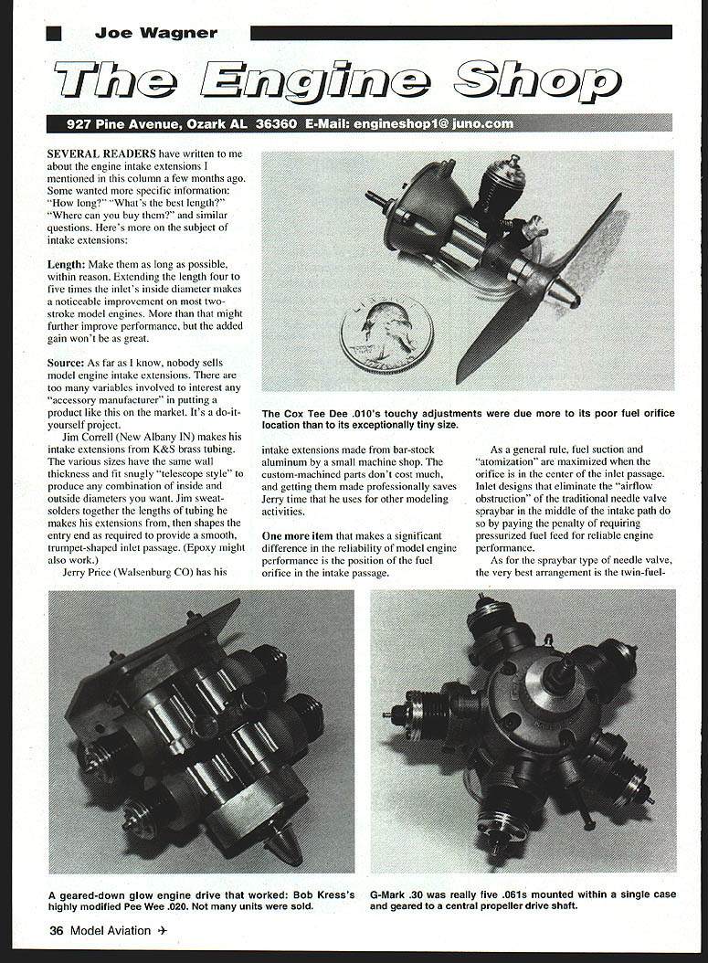
- In general, fuel suction and atomization are maximized when the fuel orifice is centered in the inlet passage.
- Intake designs that remove the spraybar from the airflow path (to reduce obstruction) typically require pressurized fuel feed to maintain reliable performance.
Spraybar Orifice Design and Positioning
- The best spraybar arrangement is a twin-fuel-orifice spraybar.
- Many spraybars show holes that are not exactly straight-across the bar; this is deliberate. Offsetting the holes slightly downstream of a straight-across-the-venturi position maximizes fuel suction.
- For single-hole spraybars:
- Often helps to hand-drill a matching hole directly opposite the original (use a bit held in a pin vise) to create a double-orifice. This minimizes adverse effects from needle-point eccentricity and taper.
- If you keep the factory single-orifice configuration, orient the hole pointing toward the rear wall of the intake passage, about five degrees downstream of a straight-across orientation.
- Some manufacturers aim the orifice straight downstream to encourage atomization by turbulent flow. Comparative tests by experimenters (including Jerry Price and Frank Williams) show no power loss from a sideways-oriented spraybar orifice and in many cases improved running reliability.
Geared Two-Stroke Engines — Why They’re Problematic
- Electric motors deliver essentially uniform torque, so geared drives handle loading well. Two-stroke engines deliver power in impulses; gears experience shock loading from each impulse, which shortens gear life and reduces reliability.
- The single drive tooth on the crank gear that first enters mesh during a power stroke takes the brunt of each impulse—this concentrated shock is the core problem.
- Historical attempts and lessons:
- Bob Kress marketed a gear-reduction version of the Cox Pee Wee .020 and solved gear failures by adding a flywheel to absorb impulse shocks. The fix worked but added significant weight—nearly tripling the powerplant installation mass.
- Du-Bro’s reduction/prop-drive unit used a flywheel and a toothed timing-belt to reduce gear shock for giant-scale use. It solved the technical problem but was bulky, heavy, and expensive relative to the engines it was meant to drive.
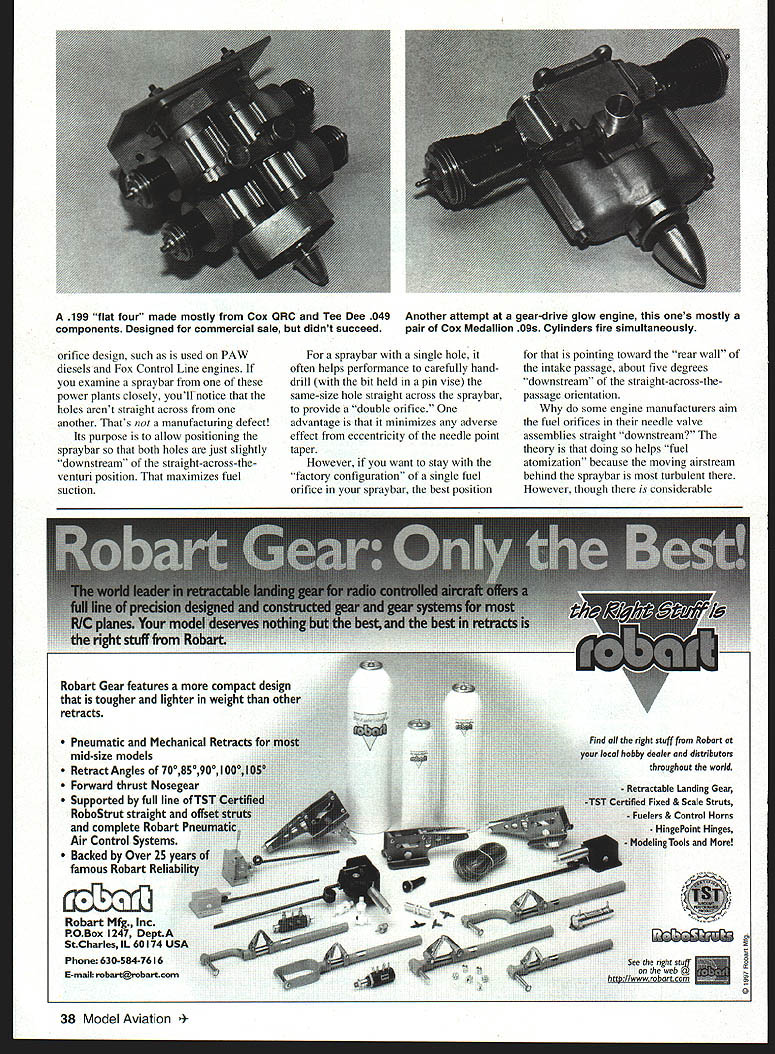
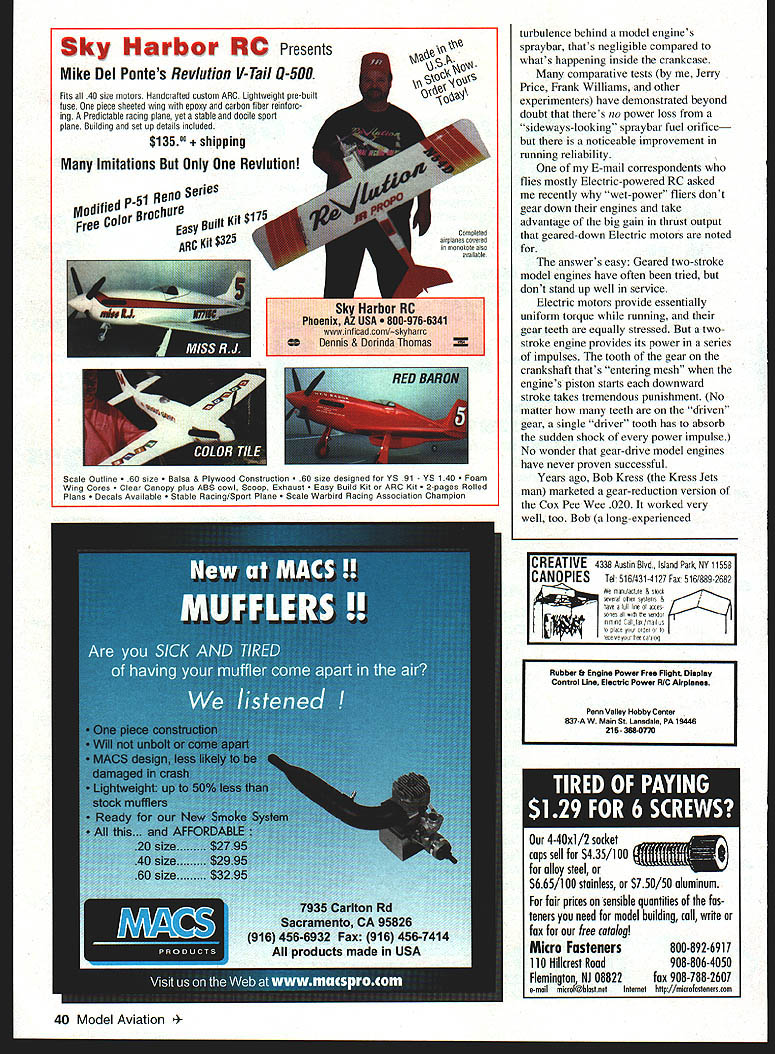
- Several multicylinder projects (e.g., G-Mark 30 five-cylinder) and custom multi-engine gearings were produced in small numbers; most were impractical for regular flying and often became display pieces. Some custom Cox-based multicylinders ran, but gear failures and lack of commercial viability were common.
- Note on propeller acting as flywheel: while the prop has flywheel effect, on gear-drive setups the prop is on the driven shaft. That increases the load on the single drive gear tooth that absorbs each impulse (it must handle both torque and inertial flywheel load), worsening the shock problem.
Cylinder Hold-Down Screw Tightness — A Practical Tip
- Cylinder hold-down screw tightness significantly affects engine performance.
- Anecdote: At the 1959 Nationals, while testing a K&B Greenhead .15, adjusting the three cylinder hold-down screws while the engine ran changed rpm by as much as 300 rpm (about 2.5% at 12,000 rpm). This demonstrates that uneven or improper torque on hold-down screws can alter compression, sealing, and thus power output.
- Check and regularly re-torque cylinder hold-down screws to ensure consistent performance.
If you have specific engines or intake geometries in mind, provide the make/model and inlet diameter and I can suggest tailored dimensions and shaping details.
Transcribed from original scans by AI. Minor OCR errors may remain.

