
The Engine Shop
Joe Wagner
Contact
- 927 Pine Avenue, Ozark, AL 36360
- E-Mail: engineshop1@juno.com
Compressed-air motors: a brief history
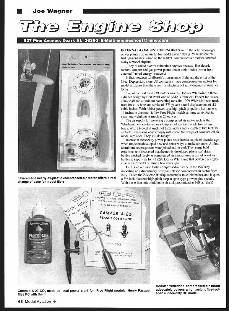
Internal-combustion engines aren't the only piston-type power plants useful for model aircraft. Years before the first "gas engines" came on the market, compressed-air motors powered many model airplanes. They're called motors rather than engines because, like electric motors, compressed-gas power plants obtain their motive power from external, stored-energy sources.
Between Lindbergh's transatlantic flight and the onset of the Great Depression, more U.S. companies made compressed-air motors for model airplanes than there are manufacturers of glow engines in America today.
The Hoosier Whirlwind
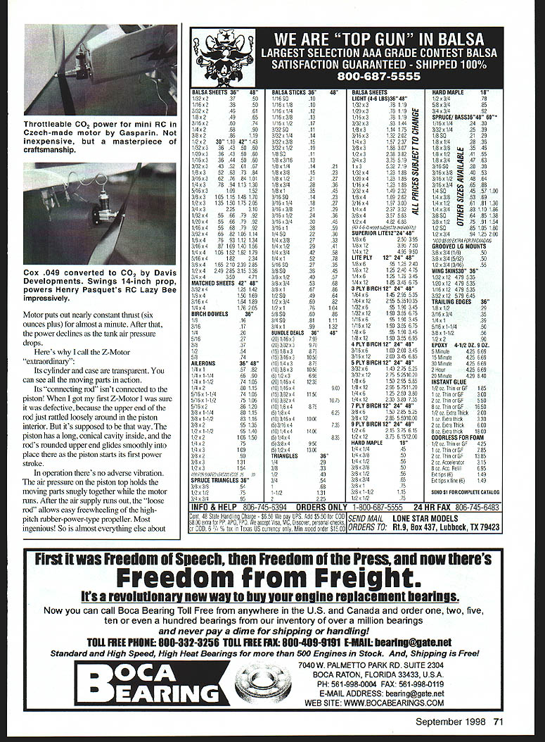
One of the best pre-1930 motors was the Hoosier Whirlwind, a three-cylinder design by Bert Pond, one of AMA's founders. Except for its steel crankshaft and aluminum connecting rods, the 1929 Whirlwind was made from brass. A bore and stroke of .375 gave it a total displacement of .12 cubic inches. With rubber-power-type high-pitch propellers from nine to 14 inches in diameter, it flew Free Flight models as large as six feet in span and weighing as much as 20 ounces.
The air supply for a compressed-air motor such as the Whirlwind was contained in a long cylindrical tank made from shim brass. With a typical diameter of three inches and a length of two feet, air-tank dimensions very strongly influenced the design of compressed-air model airplanes — and still do today.
Revival: modern air tanks and the Z-Motor
Interest in these early power plants resurfaced a couple of decades ago when modelers developed new and better ways to make air tanks. At first, aluminum beverage cans were joined end-to-end. Then experimenters discovered that plastic soft-drink bottles worked nicely as compressed-air tanks. Pairs of one-liter bottles have been used successfully to supply air for vintage motors.
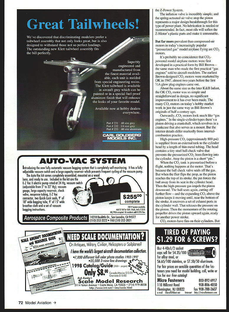
Bert Pond returned to the compressed-air scene in the 1980s by importing an extraordinary, nearly all-plastic compressed-air motor from Italy: the Z-Motor. Its displacement is .04 cubic inches, and it spins a 7-1/2-inch-diameter high-pitch prop at sport-type glow engine speeds. With a one-liter soft-drink bottle air tank pressurized to about 160 psi, the Z-Motor produces nearly constant thrust (over six ounces) for almost a minute before power declines as tank pressure falls.
Notable features of the Z-Motor:
- Transparent cylinder and case — you can see all the moving parts in action.
- A "connecting rod" that isn't rigidly attached to the piston. The rod's rounded upper end glides into a conical cavity in the piston on the first power stroke; air pressure holds the parts snugly together during operation.
- After the air supply runs out, the loose rod allows easy freewheeling of high-pitch propellers.
- A simple inflation valve and a spring-actuated air valve atop the piston represent a major design breakthrough for this type of power plant.
- No lubrication is needed or recommended; most oils will soften the Z-Motor's parts and render it unrunnable.
CO2 motors: evolution and operation
CO2-powered model motors are far more prevalent today than compressed-air motors. It's probably no coincidence that CO2-powered motors were first developed in practical form by Bill Brown — the same man who made the first practical "gas engines" sold to aircraft modelers. The earliest Brown-designed CO2 motors were marketed by OK in 1947, almost two years before the first 1/2A glow-plug engines appeared.
Outwardly, CO2 motors resemble "gas engines." Single-cylinder types have a piston driving a crankshaft that revolves in a crankcase which also serves as a mount. Internally, however, they differ markedly from internal-combustion practice.
High-pressure CO2 (approximately 800 psi) is supplied from an external tank to the cylinder head by thin metal tubing. The head contains a tiny steel ball check valve that prevents pressurized CO2 from entering the cylinder. Atop the piston is a short pin.
When the CO2 tank is pressurized before flight, nothing happens because the ball check valve seals the gas. But when the filler plug is opened at the point the piston reaches the top of its stroke, the pin forces the ball away from its seat. High-pressure gas then impels the piston downward. The ball reseats, cutting off further flow, and the expanding CO2 above the piston keeps it moving until, near the end of the stroke, it uncovers exhaust ports in the cylinder wall and releases the pressure. The propeller's momentum then drives the piston upward for another power stroke.
CO2 motors have fins on their cylinders — not cooling fins as on glow engines, but heating fins. As the high-pressure CO2 expands it gets extremely cold; heat supplied to the cylinder assists the expansion and increases power output. The warmer the cylinder, the more power a CO2 motor develops.
Wear, materials, and the Gasparin motors
Lubrication is a challenge for compressed-gas motors: high-pressure air or CO2 quickly blows away most oils added before startup. However, these motors operate at room temperature and are lightly stressed, so wear rates are low. The major cause of motor wear is dust contamination on the flying field.
Some manufacturers tried nylon plastic pistons to reduce friction (the British Teffo is one example). Though these worked for a while, they did not provide as consistent performance or as long a life as the all-metal motors made by Brown.
Czech-made motors designed and developed by Stefan Gasparin are now widely used. They come in an incredible range of sizes, from an unbelievably tiny three-cubic-millimeter (≈0.0002 cubic inch) motor weighing less than a new dime, up to 14-cylinder radials.
One Gasparin CO2 motor is equipped with an RC throttle: a .307 cc (about .020 cubic inch) single-cylinder motor that swings a seven-inch prop and can power mini-RC models of roughly 120 square inches of wing area and a total weight around five ounces. Henry Pasquet (Ellisone, MO) has flown RC models with this throttleable CO2 motor for years — and with many of the smaller motors too. Henry regularly brings an ever-growing fleet of CO2-powered radio-control miniatures to the annual SMALL (Small Model Aircraft Lovers' League) meet in Little Rock.
Free Flight CO2 models flown every Sunday morning at Balboa Park (a suburban flying site near Van Nuys, CA) demonstrate the trouble-free flyability of CO2 motors.
CO2 fueling and charging techniques
The only problematic area in operating CO2 motors is fueling. Unlike the early OK motors that used a heavy steel Sparkletts cylinder in a filler attached to the power plant and carried during flight, most modern CO2 motors use refillable aluminum tanks. Refilling these is something of an art.
There are two distinct types of CO2 fills:
- Gas fill — pressurizes the motor's tank with CO2 gas; used for short runs.
- Liquid fill — charges the tank with liquid CO2, providing a much longer and more constant-speed run time.
The difference depends on the orientation of the CO2 filler supply reservoir during filling. If the supply container (Sparkletts capless charger or a five-pound artist's airbrush bottle) points upward, the model's tank receives a gas fill. If the reservoir points downward, liquid CO2 charges the motor tank.
Connecting the model to the reservoir without losing pressure is the tricky part. The standard method is to hand-connect a small male fitting (attached by thin tubing to the charger) to a mating pressurized fitting on the model. Although CO2 pressure is around 800 psi, the fittings and O-rings are very small and require little force to hold during charging. Gas leakage, however, can be a nuisance.
Bill Brown's charging connectors were prized for their freedom from leakage because they used tapered mating surfaces, which sealed well during the charge. After Brown suffered a stroke, his CO2 products became unavailable. Current Gasparin (GMOT) connectors use straight-sided mating parts and can be prone to leakage if not precisely aligned during charging.
Safety, handling, and advantages
Despite the cold produced during CO2 expansion and charging, there's virtually no danger of frostbite while operating CO2 model motors. The liquid CO2 in the reservoir remains at normal air temperature. Cooling occurs during charging and when the motor runs (motors often get cold enough to form frost), but motor components have so little mass that there's no risk of a fingertip being frozen to a CO2 motor, its tank, or plumbing.
One of the best features of CO2 motor operation is quietness. These little power plants produce a definite piston-engine sound at such a low level that they are unobtrusive in most flying sites.
Summary
Compressed-air and CO2 motors have a long, practical history in model aviation. From brass Whirlwinds to transparent Z-Motors and the wide variety of Gasparin CO2 motors, these stored-energy power plants remain viable, interesting, and remarkably capable alternatives to glow engines for many modelers.
Transcribed from original scans by AI. Minor OCR errors may remain.

