
Engine Technique
Don Jehlik
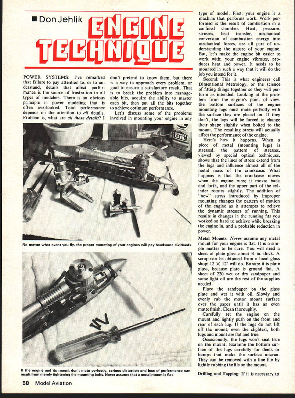
POWER SYSTEMS: I've remarked that failure to pay attention to, or to understand, details that affect performance is the source of frustration to all types of modelers. There is an obvious principle in power modeling that is often overlooked. Total performance depends on the attention to all details. Problem is, what are all those details? I don't pretend to know them, but there is a way to approach every problem, or goal to ensure a satisfactory result. That is to break the problem into manageable bits, acquire the ability to master each bit, then put all the bits together to achieve optimum performance.
Let's discuss some of the problems involved in mounting your engine in any type of model. First: your engine is a machine that performs work. Work performed is the result of combustion in a confined chamber. Heat, pressure, stresses, heat transfer, mechanical conversion of combustion energy into mechanical forces, are all part of understanding the nature of your engine. But, let's make the engine bit easier to work with; your engine vibrates, produces heat and power. It needs to be mounted in such a way that it will do the job you intend for it.
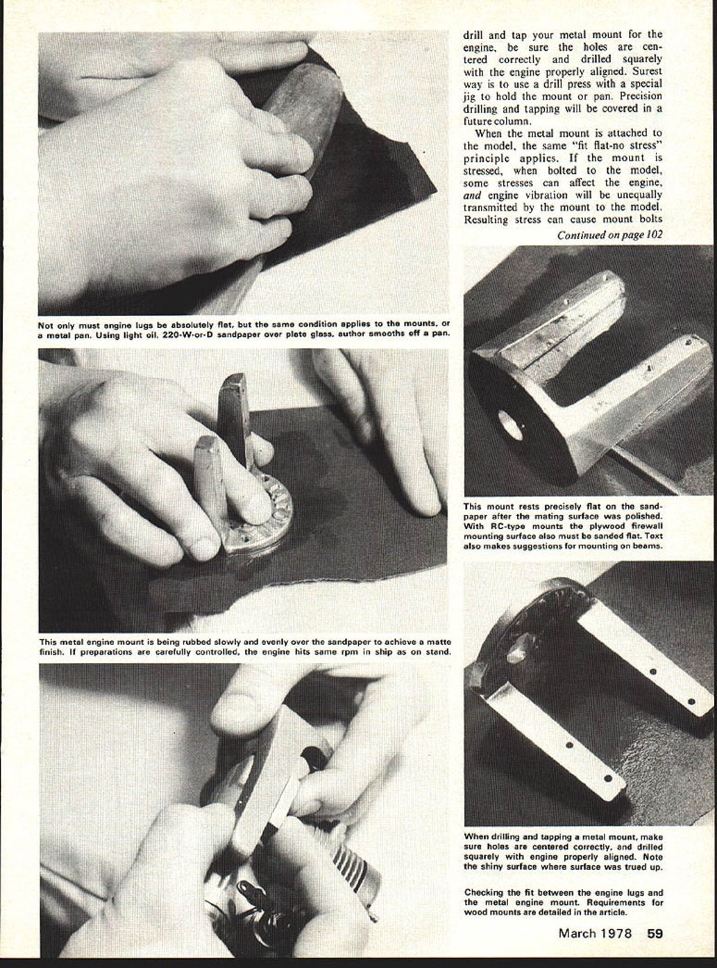
Second: This is what engineers call Dimensional Metrology, or the science of fitting things together so they will perform as intended. Looking at the problem from the engine's point of view, the bottom surfaces of the engine mounting lugs must mate perfectly with the surface they are placed on. If they don't, the lugs will be forced to change their shape slightly when bolted to the mount. The resulting stress will actually affect the performance of the engine.
Here's how it happens. When a piece of metal (mounting lugs) is stressed, the pattern of stresses, viewed by special optical techniques, shows that the lines of stress extend from the lugs and influence almost all of the metal mass of the crankcase. What happens is that the crankcase moves when the engine runs; it moves back and forth, and the upper part of the cylinder rotates slightly. The addition of "new" stress introduced by improper mounting changes the pattern of motion of the engine as it attempts to relieve the dynamic stresses of running. This results in changes in the running fits you worked so hard to achieve while breaking the engine in, and a probable reduction in power.
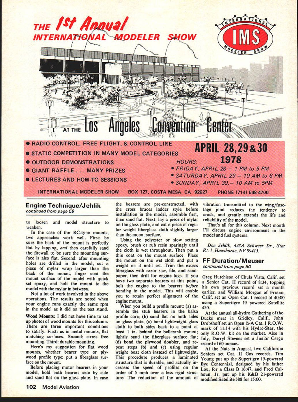
Metal Mounts: Never assume any metal mount for your engine is flat. It is a simple matter to be sure. You will need a sheet of plate glass about 1/4 in. thick. A scrap can be obtained from a local glass shop; 12 x 12 will do. Be sure it is plate glass, because plate is ground flat. A sheet of 220 wet or dry sandpaper and some light oil are the rest of the supplies needed.
Place the sandpaper on the glass plate and wet it with oil. Slowly and evenly rub the motor mount surface over the paper until it has an even matte finish. Clean thoroughly.
Carefully set the engine on the mount and lightly push on the front and rear of each lug. If the lugs do not lift off the mount, even the slightest, both lugs and mount are flat and true.
Occasionally, the lugs won't seat true on the mount. Examine the bottom surface of the lugs carefully for dents or bumps that make the surface uneven. They can be removed with a fine file by lightly rubbing the file on the mount.
Drilling and Tapping: If it is necessary to drill and tap your metal mount for the engine, be sure the holes are centered correctly and drilled squarely with the engine properly aligned. Surest way is to use a drill press with a special jig to hold the mount or pan. Precision drilling and tapping will be covered in a future column.
When the metal mount is attached to the model, the same "fit flat-no stress" principle applies. If the mount is stressed, when bolted to the model, some stresses can affect the engine, and engine vibration will be unequally transmitted by the mount to the model. Resulting stress can cause mount bolts to loosen and model structure to weaken.
In the case of the RC-type mounts, two approaches work well. First: be sure the back of the mount is perfectly flat by lapping, and then carefully sand the firewall to be sure the mounting surface is also flat. Second: after mounting holes are drilled in the model, cut a piece of mylar wrap larger than the back of the mount, finger coat the mount surface of the model with quick set epoxy, and bolt the mount to the model with the mylar in between.
Not a lot of work involved in the above operations. The results are noted when your engine runs exactly the same rpm in the model as it did on the test stand.
Wood Mounts: I did not have time to set up photos of wood mounts for this column. There are three important conditions to satisfy. First: as in metal mounts, flat matching surfaces. Second: stress free mounting. Third: durable mounting.
Here's my suggestion for flat wood mounts, whether bearer type or plywood profile type: put a fiberglass surface on the mount.
Before placing motor bearers in your model, hold both bearers side by side and sand flat on the glass plate. In case the bearers are pre-constructed, with the cross braces ladder style before installation in the model, assemble first, then sand flat. Next, lay a piece of mylar on the glass plate, and cut a piece of regular weight fiberglass cloth slightly larger than the mount surface.
Using the polyester or slow setting epoxy, brush or rub resin sparingly until the cloth is wet throughout. Then put a thin coat on the mount surface. Place the mount on the wet cloth and put a weight on it until set. Trim the excess fiberglass with razor saw, file, and sandpaper, then drill for engine lugs. If you have two separate bearers at this point, bolt the engine to the bearers before bonding in the model. This will enable you to retain perfect alignment of the engine mount.
When you build a profile mount: (a) assemble the stub bearers in the balsa profile core; (b) sand flat on both sides on glass plate; (c) bond lightweight glass cloth to both sides back to a point at least 1 in. behind the bellcrank mount; lightly sand the fiberglass surface flat; (d) bond the plywood doubler, and repeat steps (b) and (c) using regular weight boat cloth instead of lightweight. This procedure produces a laminated structure that is durable, and actually increases the speed of profiles on the order of 5 mph over a less rigid structure. The reduction of the amount of vibration transmitted to the wing/fuselage joint reduces the tendency to crack, and greatly extends the life and reliability of the model.
That's all for this column. Next month I'll discuss engine environment in the model and fuel systems.
Don Jehlik, 438A Schweer Dr., Star Rt. 1, Hawthorne, NV 89415.
Transcribed from original scans by AI. Minor OCR errors may remain.

