
Engine Technique
SEEMS LIKE the 12 days of Christmas, the big day a few days away at this writing, and the first four of a dozen planned articles on power systems are completed. I am receiving letters, will respond to all personally, and print the good information that comes in. Thanks for your interest in the column!
Royal Kramer, from Allentown, Pa., writes. Why disassemble engines from .15 to .60 before running? The answers are: (1) you don't have to; but, if you want to be sure of maximum life and performance from your engine, that's how to do it. It's like taking delivery on a new car and then checking it out and taking it back to the dealer to fix minor problems. In this case, you are the buyer and the fixer. (2) To develop (if you wish) personal skills that can add to the enjoyment and results you achieve in power modeling. Over the years I've heard many modelers remark that they get real satisfaction from their ability to "set up" engines. In some, if not all, competitive events, winning just doesn't happen, unless specialized attention is paid to getting specific performance from an engine.
Dr. Gene Smith, from Stillwater, Okla., writes, "I have really enjoyed your articles on new engine preparation. I gave an X40 'the treatment' and as you said, you can feel the difference." Gene dropped a nice hint in his letter. He purchased a SONAC (denture ultrasonic cleaner) for about $15 (sale locally for under $10) and "after five minutes of cleaning the new engine parts, the bottom of the pan looked like I was panning for silver."
He said my cleaning solution formula softened the plastic pan on the cleaner. That's easily solved. Take a piece of Saran Wrap and put it in the pan, then pour in the cleaning solution. When you are through, pick up the Saran Wrap "bag" and pour the solution through a coffee filter into a jar. Seal the jar tightly for storage and throw the wrap and filter away. Gene said this is fun! Wonder if he thinks that really is silver in that pan? If he keeps writing these kind of letters I'll send him some gold ore my boys have picked up out here and let him separate it!
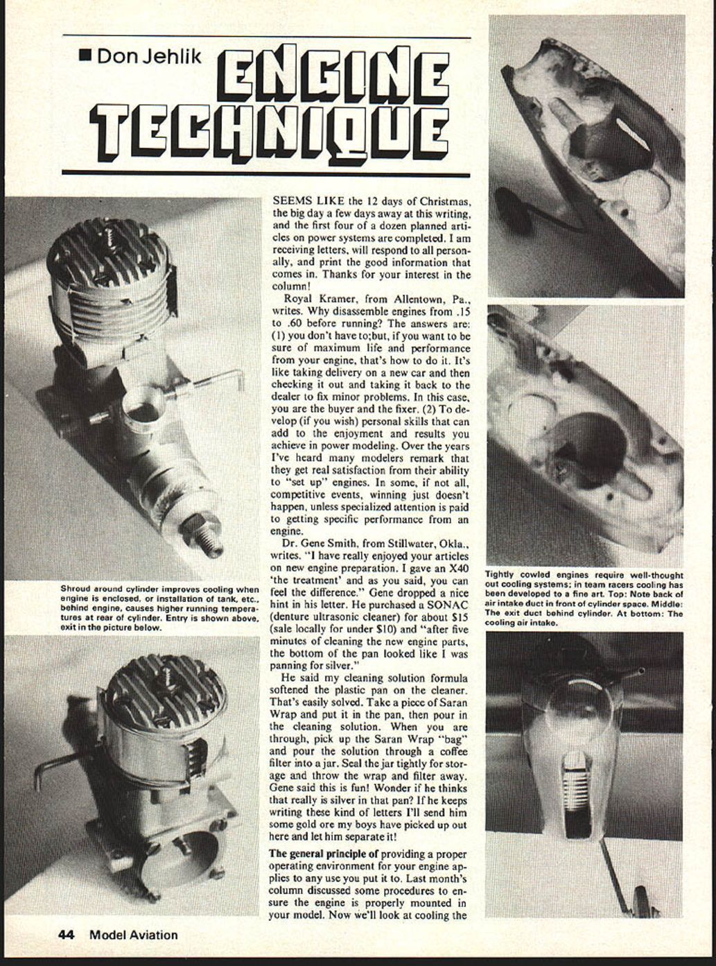
The general principle of providing a proper operating environment for your engine applies to any use you put it to. Last month's column discussed some procedures to ensure the engine is properly mounted in your model. Now we'll look at cooling the cylinder. Don't assume that the engine you have is designed by the manufacturers to cool itself, that is, operate within an acceptable temperature range when you use it. Let's break cooling into three categories: (1) air cooling, (2) air/heat sink cooling, and (3) water cooling.
Air Cooling: Usually confined to airplane applications. Air cooling ranges from "hang it in the breeze" to carefully designed cooling systems involving cooling ducts, fans, etc. All air-cooled applications can benefit from some thought.
Example: Hang it in the breeze in a profile model. Cooling air is blown from the prop and air stream over the engine. It does not flow smoothly (laminar flow) over the entire cylinder. Flow at the front tends to be laminar until the air tries to flow around the back of the engine, where it separates from the engine, leaving an area of rough (turbulent) flow at the rear. The turbulent flow does not transfer heat (cool) the engine as well as the laminar flow. Net result is the front of the engine is cooler than the back. You might say so what? That's what happened on the test stand, too, and since the engine was run in that way it should be okay when it flies. Not necessarily so. Engines have a way of running too hot in the model and not on the test stand, for a variety of reasons.
You may have mounted your tank too close behind the engine, thereby enlarging the area of turbulent air at the back of the engine. If the engine does run hotter at the rear, the temperature differential between front and rear of the cylinder will be greater. The engine will compensate for this condition by wearing more clearance between piston and sleeve. Early Supertigre engines came into the U.S. with instructions printed in Italian. One portion stated that, after break-in, the engine should be mounted in the model and flown 20-30 flights, thereby "settling in" to the model before maximum performance is reached. In many cases, that is exactly what happens.
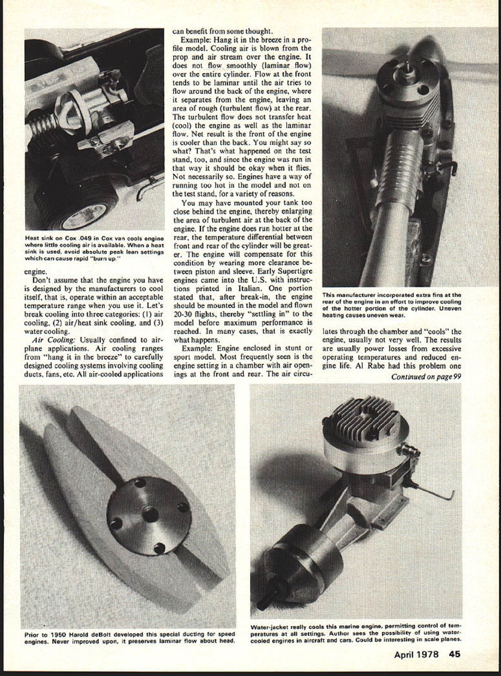
Example: Engine enclosed in stunt or sport model. Most frequently seen is the engine setting in a chamber with air openings at the front and rear. The air circulates through the chamber and "cools" the engine, usually not very well. The results are usually power losses from excessive operating temperatures and reduced engine life. Al Rabe had this problem one
Engine Technique
It worked out that, by using an X-40 (.700 stroke) crankshaft, the displacement could be reduced to .357—just what we wanted. As in any stroke change, the liner must be adjusted (upward for decreased stroke) to maintain the proper cylinder timing.
The hybrid ST-36RRV performed on a par with the standard ST-G-21-3S on 30% nitro. However, the ringed piston would allow us to run 55% nitro, still with dependable restarts. Therefore, we were able to show some improvement over the standard .35. All of the testing was done with a suction venturi. We also tried the same engine with a G-21-29 crank (.668 stroke), which lowered the displacement to .340, but this had only limited success.
It quickly became obvious that we still needed Schnuerle ports. We tried a bar-stock engine designed and built by Henry Nelson, using a ST lapped piston and crank. This ran extremely well, but obviously was too costly. We then looked at the OS-40SR and the HP 40, which we were using with such good success in Rat Race. I decided to attempt to destroke the 40 cranks on these to achieve a .36 displacement.
After about three weeks of failures and scrapped parts, I finally got a HP36FR together. It dramatically "blew the doors off" of everything else. We then proceeded to make both an OS36RRV and FV along with a HP 36RRV. All were successful, except for the OS36FV, which managed to keep throwing the crank bearings out of the front end. It turned out that the HP's required a new stroke of .667" ± .001" and the OS a .657" ± .001" for legal displacements. Again, the liners had to be shimmed on all of these. The HP36FV and RV essentially ran the same, while the OS performed slightly better than both of these.
The next step was to determine the maximum venturi choke area that we could get away with. Initially, we used a nominal .315" diameter with a stock ST spray bar going through the middle. We tried many different lengths and angles and eventually found that a .355" ± .005" diameter venturi with a 7° entrance angle worked about the best in flight testing, and we have since stuck with that. It is interesting to note that we measured a 400–500 rpm, or about 5–8 mph gain, between the .315" and the new .355" diameter.
I have had discussions with both John Maloney of World Engines and Jerry Nelson of Midwest (H.P.) concerning the production of these .36 engines. I have supplied both of them engines and specifications to forward to the respective factories. Meanwhile both Fox and K&B now are producing Schnuerle .36's, although neither are ringed and don't seem to restart consistently.
Since the 1978–79 rules for Slow Rat require quantity manufactured engines and parts, Fox and K&B may have a lock on the market, at least until either OS or HP come out with a ringed-piston, ball-bearing, Schnuerle-ported .36 engine.
We found that a basic 8×8 fiberglass prop (Bartel or Kelly) pitched to 7 in., and thinned down a little, provides the best performance. Our engines swing this prop between 19,200 and 20,000 static ground rpm.
Whatever engine you use either now or in the future, I think that you will find the Bobcat to be a very efficient no-nonsense model capable of winning performances for years to come.
Year at the Nats. I examined his engine and found it okay. There was evidence of overheating. I suggested fabricating a tin can cooling shroud wrapped around the back of the cylinder and a little more nitro in the fuel. The overheating problem which created the power loss was solved.
Example: Air duct cooled engine. This is really the way to go for all enclosed engines. Harold Debolt worked up a properly designed duct cooling system before 1950 that really hasn't been improved on. The principle is to control cooling air by forcing it to flow laminar all the way around the cylinder. He achieved nearly even cooling front to back. I really believe almost all enclosed engine models can and should incorporate air duct cooling.
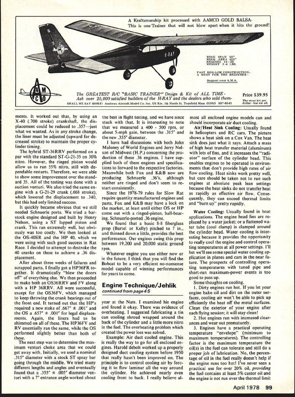
Air/Heat Sink Cooling: Usually found in helicopters and RC cars. The picture shows a heat sink on a Cox Van. The heat sink does just what it says. Attach a mass of high heat transfer material (aluminum) with lots of fins, and it increases the "radiator" surface of the cylinder head. This enables engines to be operated in environments that don't provide high rates of air flow cooling. Heat sinks work pretty well, but care should be taken not to run such engines at absolute peak lean settings because the heat sinks do not transfer heat as rapidly as effective air flow. Consequently, they can exceed thermal limits and "burn up" pretty rapidly.
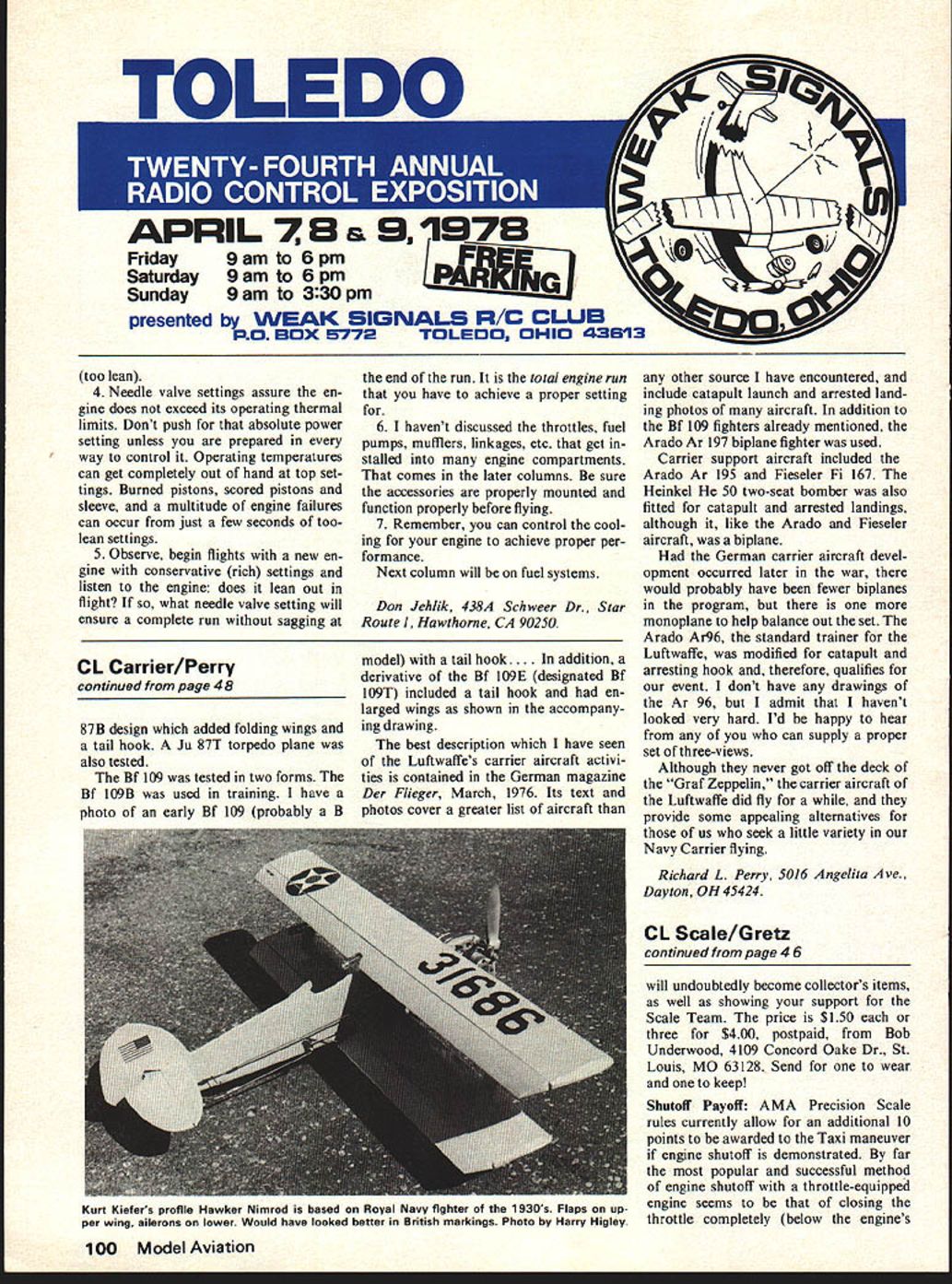
Water Cooling: Usually found in boat applications. The engine head fins are replaced by a water jacket; or a flattened water tube (cool clamp) is clamped around the cylinder head. Water cooling is interesting because it provides the opportunity to really cool the engine and control operating temperatures at all power settings. I'll bet we'll see some special water cooling application in planes and cars in the near future. The prospects of controlling operating temperatures with tuned pipe and short-run maximum-power events is too good to pass up.
Some thoughts on cooling.
- Dirty engines run hot. If you let your engine bake oil and dirt on the outer surfaces, cooling air won't be able to pick up efficiently the heat off the metal surfaces. Clean the exterior of your engine after each flying session; it will stay clean!
- Hot engines run hot with increased clearances and wear out prematurely.
- Engines have a practical operating temperature "envelope" (minimum to maximum temperatures). The controlling factor is the maximum temperature the oil(s) in the fuel can tolerate and still do a proper job of lubrication. No, the percentage of oil in the fuel really doesn't help if the engine runs too hot! I've never seen a practical use for over 20% oil, providing the fuel contains at least 5% castor oil and the engine is not run over the thermal limit.
(too lean).
- Needle valve settings assure the engine does not exceed its operating thermal limits. Don't push for that absolute power setting unless you are prepared in every way to control it. Operating temperatures can get completely out of hand at top settings. Burned pistons, scored pistons and sleeve, and a multitude of engine failures can occur from just a few seconds of too-lean settings.
- Observe, begin flights with a new engine with conservative (rich) settings and listen to the engine; does it lean out in flight? If so, what needle valve setting will ensure a complete run without sagging at the end of the run. It is the total engine run that you have to achieve a proper setting for.
- I haven't discussed the throttles, fuel pumps, mufflers, linkages, etc. that get installed into many engine compartments. That comes in the later columns. Be sure the accessories are properly mounted and function properly before flying.
- Remember, you can control the cooling for your engine to achieve proper performance.
Next column will be on fuel systems.
Don Jehlik, 4384 Scherer Dr., Star Route 1, Hawthorne, CA 90250.
Transcribed from original scans by AI. Minor OCR errors may remain.

