
Engine Technique - Don Jehlik
FUEL SYSTEMS: The ideal fuel system isn't here yet, but a lot of work has been put into making engines run in optimum fashion. Let's begin by taking a look at some of the forces that affect the fuel delivered to your engine: gravity, centrifugal force, partial vacuum, turbulent and laminar flow.
Starting with the fuel tank, there are many different types of tanks, but they all serve one basic purpose, to hold the engine's fuel supply. Tanks can be further broken into two basic categories: pressure and demand. Pressure tanks are the expanded bladder type, or hard tanks with an external pressure source—such as crankcase, muffler, or pipe pressure supplied to the tank. They supply fuel to the engine by forcing fuel to the carburetor. Demand tanks are unpressurized bladder or hard tanks that supply fuel to the engine as the result of the partial vacuum (fuel draw) created by the flow of air through the carburetor venturi.
It's hard to understand that the type of tank (pressure or demand) doesn't change the fact that, in nearly all applications, the fuel supplied to the engine varies in quantity throughout the run. This means that the needle valve setting will be a compromise that must allow for the larger amount of fuel flow provided at the beginning of the run and smaller amount of flow at the end.
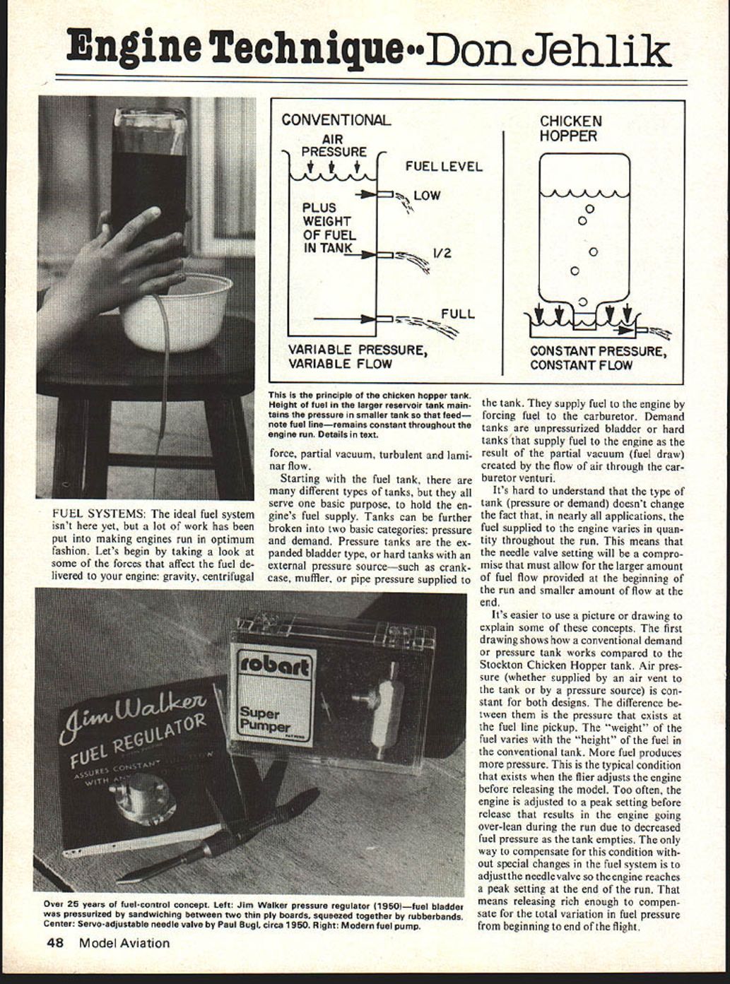
It's easier to use a picture or drawing to explain some of these concepts. The first drawing shows how a conventional demand or pressure tank works compared to the Stockton Chicken Hopper tank. Air pressure (whether supplied by an air vent to the tank or by a pressure source) is constant for both designs. The difference between them is the pressure that exists at the fuel line pickup. The "weight" of the fuel varies with the "height" of the fuel in the conventional tank. More fuel produces more pressure. This is the typical condition that exists when the flier adjusts the engine before releasing the model. Too often, the engine is adjusted to a peak setting before release that results in the engine going over-lean during the run due to decreased fuel pressure as the tank empties. The only way to compensate for this condition without special changes in the fuel system is to adjust the needle valve so the engine reaches a peak setting at the end of the run. That means releasing rich enough to compensate for the total variation in fuel pressure from beginning to end of the flight.
The chicken hopper tank is designed to deliver constant fuel pressure at the fuel line pickup. The fuel pickup is located in a separate constant-pressure hopper which is supplied from a larger reservoir. The relationship between air pressure and fuel head height in the small hopper tank remains essentially constant throughout the entire run.
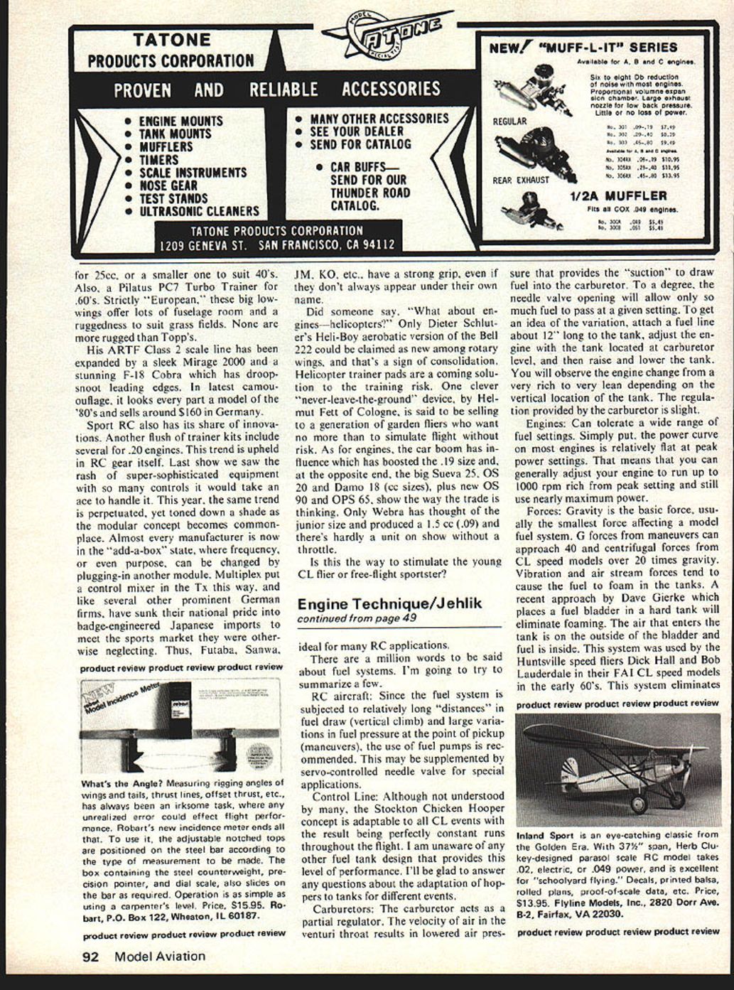
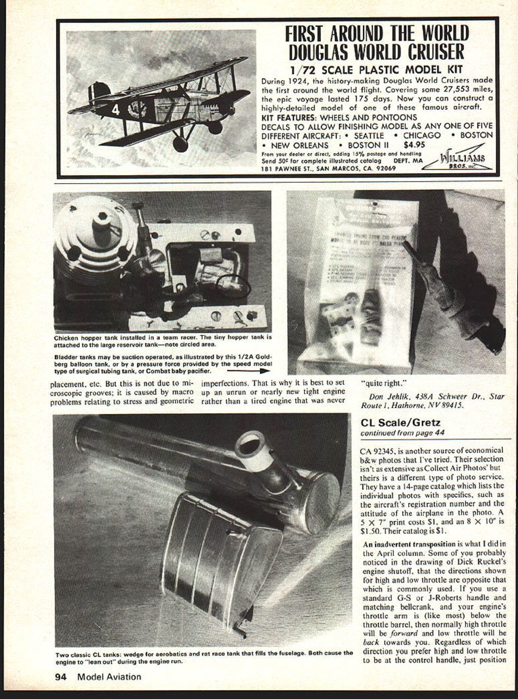
A photo of a hopper tank used in a team race installation illustrates several things. First, note the extremely small size of the hopper tank compared with the reservoir tank. Second, note that the size or shape of the reservoir tank has no effect on fuel flow to the engine. Third, the location of the hopper tank relative to the engine carburetor is critical because the constant-pressure fuel source provided by the hopper tank enables you to set an optimum needle valve setting which will remain constant throughout the flight.
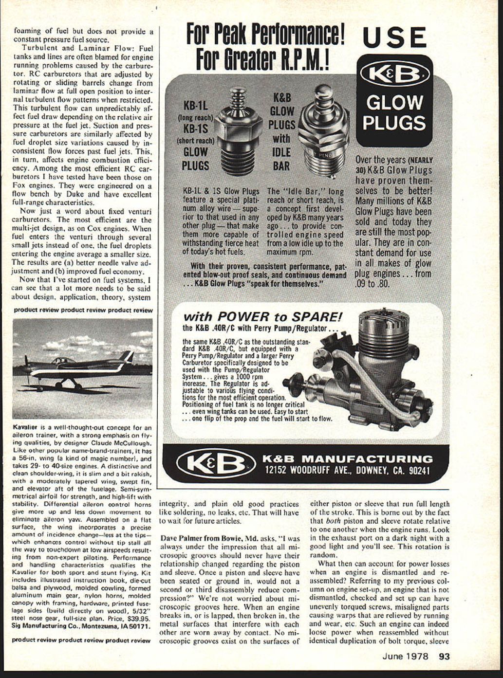
A Goodyear tank adapted as a hopper tank is an example of adapting the principle to a specialized event. Similar hoppers can be adapted to CL stunt tanks, speed tanks, etc. RC boats have adapted the idea by locating a small hopper tank (1 oz.) near the carburetor, connecting the main reservoir tank located aft in the boat. Model race cars and RC tethered cars can also benefit from similar installations.
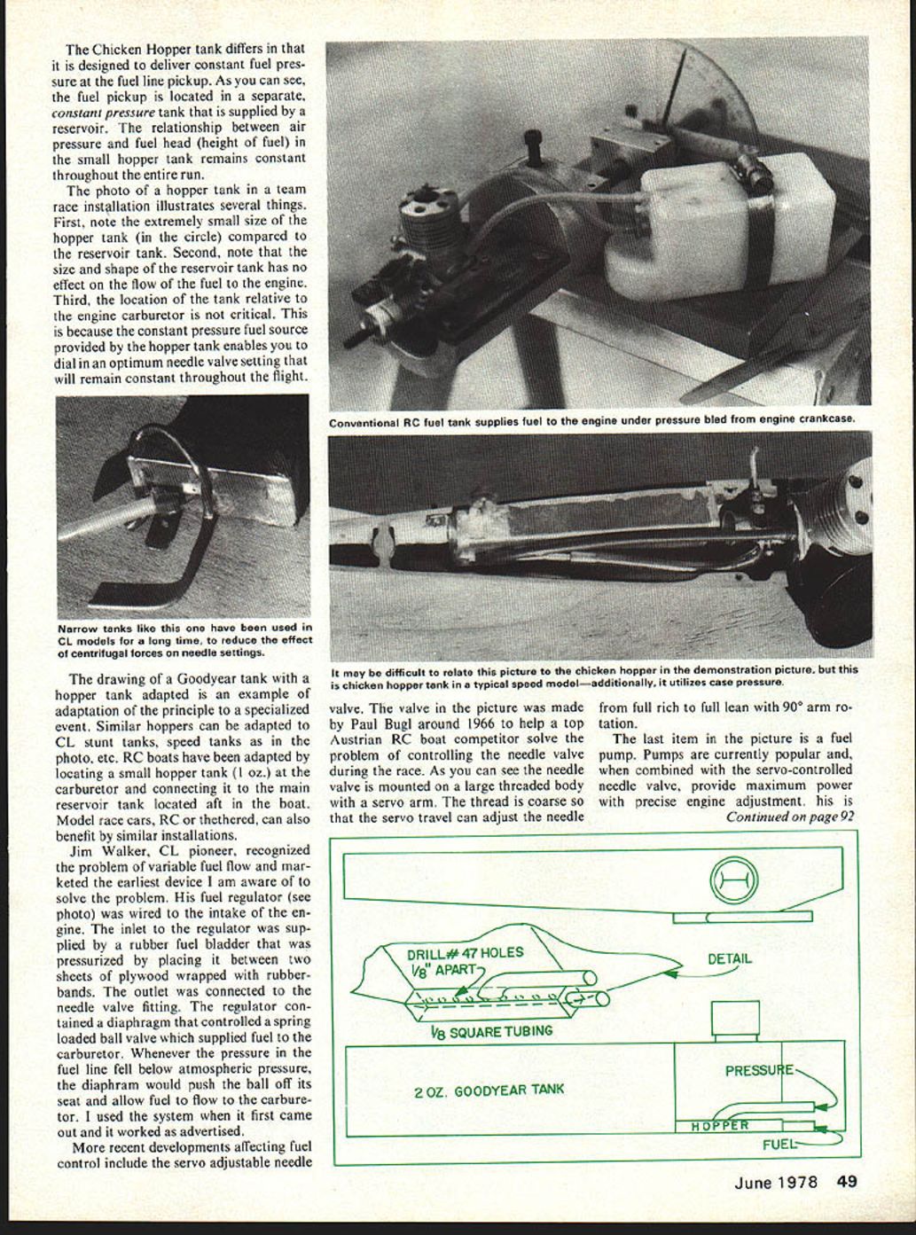
Jim Walker, a CL pioneer, recognized the problem of variable fuel flow and marketed the earliest device I am aware of to solve the problem—the fuel regulator. The wired intake engine inlet regulator supplied a rubber fuel bladder pressurized by sandwiching it between two thin ply boards, squeezed together by rubberbands. The outlet connected to a needle-valve fitting. The regulator contained a diaphragm-controlled, spring-loaded ball valve which supplied fuel to the carburetor. Whenever pressure in the fuel line fell below atmospheric pressure, the diaphragm would push the ball off its seat and allow fuel flow. The carburetor used this system when it first came out and it worked as advertised.
Recent developments affecting fuel control include servo a adjustable needle valve. The valve in the picture was made by Paul Bugl around 1966 to help a top Austrian RC boat competitor solve the problem of controlling the needle valve during the race. As you can see the needle valve is mounted on a large threaded body with a servo arm. The thread is coarse so that the servo travel can adjust the needle from full rich to full lean with 90° arm rotation.
The last item in the picture is a fuel pump. Pumps are currently popular and, when combined with the servo-controlled needle valve, provide maximum power with precise engine adjustment. Ideal for many RC applications.
There are a million words to be said about fuel systems. I'm going to try to summarize a few.
RC aircraft: Since the fuel system is subjected to relatively long "distances" in fuel draw (vertical climb) and large variations in fuel pressure at the point of pickup (maneuvers), the use of fuel pumps is recommended. This may be supplemented by a servo-controlled needle valve for special applications.
Control Line: Although not understood by many, the Stockton Chicken Hopper concept is adaptable to all CL events with the result being perfectly constant runs throughout the flight. I am unaware of any other fuel tank design that provides this level of performance. I'll be glad to answer any questions about the adaptation of hoppers to tanks for different events.
Carburetors: The carburetor acts as a partial regulator. The velocity of air in the venturi throat results in lowered air pressure that provides the "suction" to draw fuel into the carburetor. To a degree, the needle valve opening will allow only so much fuel to pass at a given setting. To get an idea of the variation, attach a fuel line about 12" long to the tank, adjust the engine with the tank located at carburetor level, and then raise and lower the tank. You will observe the engine change from a very rich to very lean depending on the vertical location of the tank. The regulation provided by the carburetor is slight.
Engines: Can tolerate a wide range of fuel settings. Simply put, the power curve on most engines is relatively flat at peak power settings. That means that you can generally adjust your engine to run up to 1000 rpm rich from peak setting and still use nearly maximum power.
Forces: Gravity is the basic force, usually the smallest force affecting a model fuel system. G forces from maneuvers can approach 40 and centrifugal forces from CL speed models over 20 times gravity. Vibration and air stream forces tend to cause the fuel to foam in the tanks. A recent approach by Dave Gierke which places a fuel bladder in a hard tank will eliminate foaming. The air that enters the tank is on the outside of the bladder and the fuel is inside. This system was used by the Huntsville speed fliers Dick Hall and Bob Lauderdale in their FAI CL speed models in the early 60's. This system eliminates foaming. foaming of fuel but does not provide a constant pressure fuel source.
Turbulent and Laminar Flow: Fuel tanks and lines are often blamed for engine running problems caused by the carburetor. RC carburetors that are adjusted by rotating or sliding barrels change from laminar flow at full open position to internal turbulent flow patterns when restricted. This turbulent flow can unpredictably affect fuel draw depending on the relative air pressure at the fuel jet. Suction and pressure carburetors are similarly affected by fuel droplet size variations caused by inconsistent flow forces past fuel jets. This, in turn, affects engine combustion efficiency. Among the most efficient RC carburetors I have tested have been those on Fox engines. They were engineered on a flow bench by Duke and have excellent full-range characteristics.
Now just a word about fixed venturi carburetors. The most efficient are the multi-jet design, as on Cox engines. When fuel enters the venturi through several small jets instead of one, the fuel droplets entering the engine average a smaller size. The results are (a) better needle valve adjustment and (b) improved fuel economy.
Now that I've started on fuel systems, I can see that a lot more needs to be said about design, application, theory, system integrity, and plain old good practices like soldering, no leaks, etc. That will have to wait for future articles.
Dave Palmer from Bowie, Md. asks, "I was always under the impression that all microscopic grooves should never have their relationship changed regarding the piston and sleeve. Once a piston and sleeve have been seated or ground in, would not a second or third disassembly reduce compression?" We're not worried about microscopic grooves here. When an engine breaks in, or is lapped, then broken in, the metal surfaces that interfere with each other are worn away by contact. No microscopic grooves exist on the surfaces of either piston or sleeve that run full length of the stroke. This is borne out by the fact that both piston and sleeve rotate relative to one another when the engine runs. Look in the exhaust port on a dark night with a good light and you'll see. This rotation is random.
What then can account for power losses when an engine is dismantled and reassembled? Referring to my previous column on engine set-up, an engine that is not dismantled, checked and set up can have unevenly torqued screws, misaligned parts causing warps that are relieved by running and wear, etc. Such an engine can indeed lose power when reassembled without identical duplication of bolt torque, sleeve orientation and other settings.
Engine Technique
Don Jehlik
FUEL SYSTEMS
An ideal fuel system isn't here yet; a lot of work has been put into making engines run in optimum fashion. Let's begin by taking a look at some forces that affect fuel delivered to the engine: gravity, centrifugal, and conventional air pressure — plus the weight of fuel in the tank. As the fuel level falls, pressure and therefore flow can vary. The principle behind the chicken-hopper tank is to provide a larger reservoir which maintains a constant pressure to a smaller feed tank so the fuel line pickup pressure remains essentially constant throughout the engine run.
Starting with fuel tanks: different types of tanks serve the basic purpose of holding an engine's fuel supply. Tanks can further be broken into two basic categories: pressure and demand. Pressure tanks include expanded-bladder types, hard tanks, or tanks with external pressure sources such as crankcase or muffler-pipe pressure supplied to them. The chicken-hopper is a constant-pressure, constant-flow tank which supplies fuel to the engine by forcing fuel to the carburetor.
Demand tanks are unpressurized bladder or hard tanks which supply fuel to the engine as a result of the partial vacuum or fuel draw created by air flowing through the carburetor venturi. It is hard to understand from a casual inspection whether a tank is pressure or demand, but the fact remains that in nearly all applications the quantity of fuel supplied the engine varies throughout a run. That means needle-valve setting will be a compromise: it must allow a larger amount of fuel flow at the beginning of the run and a smaller amount at the end. It's easier to use a picture or drawing to explain some concepts: a conventional demand/pressure tank arrangement varies pickup height as fuel weight changes, whereas a chicken-hopper-type small tank with a separate constant-pressure pickup maintains a constant fuel head throughout the run.
Goodyear-type hopper adaptations are an example of adapting the principle for a specialized event. Similar hoppers can be adapted for CL stunt tanks, speed tanks, photo, etc. RC boats have adapted the locating of a small hopper (1 oz) at the carburetor, connecting to a main reservoir tank located aft in the boat. Model race cars and RC tethered cars can also benefit from similar installations.
Jim Walker, a CL pioneer, recognized the problem of variable fuel flow and marketed one of the earliest devices to solve the problem — a fuel regulator wired to the engine inlet. The regulator used a rubber fuel bladder pressurized by placing it between two sheets of plywood and wrapping with rubber bands; the outlet was connected to a needle-valve fitting. The regulator contained a diaphragm-controlled, spring-loaded ball valve to supply the carburetor. Whenever pressure in the fuel line fell below atmospheric pressure the diaphragm would push the ball off its seat to allow fuel flow. When the carburetor-use system first came out it worked as advertised.
Recent developments affecting fuel control include servo a
Transcribed from original scans by AI. Minor OCR errors may remain.

