
Engine Technique
Don Jehlik
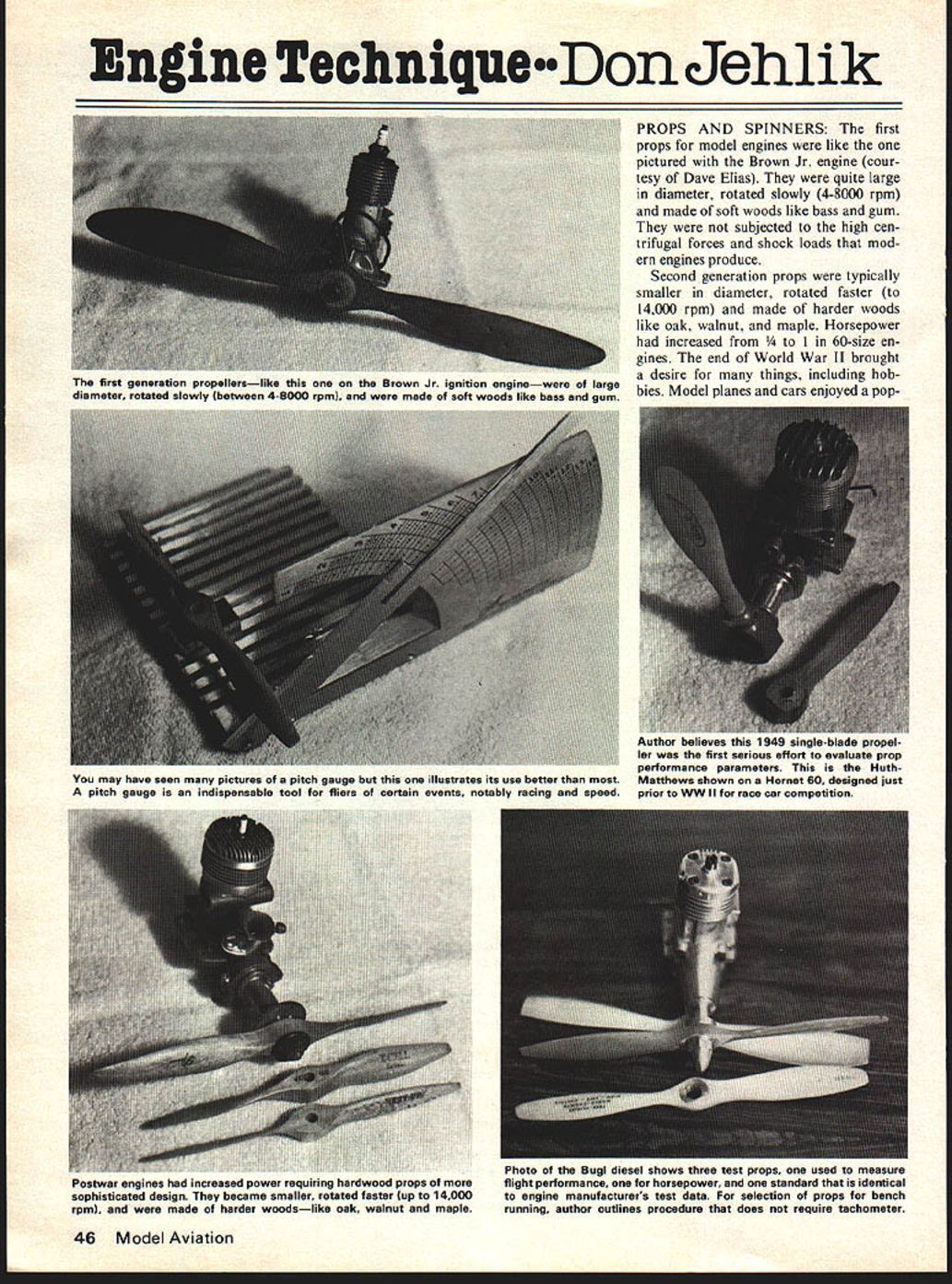
PROPS AND SPINNERS: The first props for model engines were like the one pictured with the Brown Jr. engine (courtesy of Dave Elias). They were quite large in diameter, rotated slowly (4-8,000 rpm), and made of soft woods like bass and gum. They were not subjected to the high centrifugal forces and shock loads that modern engines produce.
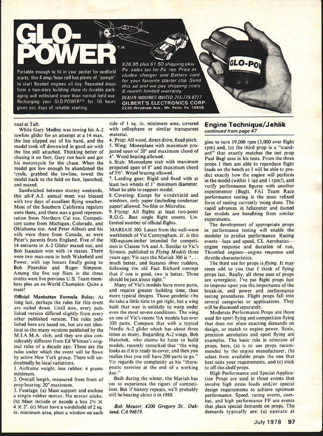
Second generation props were typically smaller in diameter, rotated faster (to 14,000 rpm) and made of harder woods like oak, walnut, and maple. Horsepower had increased from 1/4 to 1 in 60-size engines. The end of World War II brought a desire for many things, including hobbies. Model planes and cars enjoyed a popularity the next few years have not equaled since. High performance engines like the Hornet 60, pictured with the Huth-Matthews designed one-blade prop, and Edco Skydevil with hardwood props, were designed in the period just prior to WW II for race car application. Modified for the then new control-line style of flying, the speed and performance race was on.
Looking back, I believe the Irwin Huth and Wayne Mathews one-blade prop with adjustable pitch was the first serious effort made by competition fliers to optimize propeller/horsepower application. I had the privilege of talking to them at the 1949 Nats. I learned that their single-blade prop had been re-shaped, blade area optimized, airfoil in the blade modified, and pitch adjusted to allow the combination to turn at rpm that matched maximum hp of their engine. This last sentence says it all! But before I talk about optimum prop I want to mention the uses of props.
It sounds simple, but I believe props have several uses or applications, each placing a different demand on them.
The first is Bench Running: You don't really need fancy props, just ones that are appropriate and safe. In a previous column, I discussed the selection of props for bench running: (a) run props that allow the engine to initially turn at at least the rpm you expect it to run in the air. Then continue to reduce prop size until the engine runs consistently throughout the rpm envelope you intend to use in the model plus 2-3000 rpm on the top end. Don't have a tach? Here's the general rule. First, prop for engines 5-10 cc displacement: select a prop of the same pitch, but one inch less diameter, than used in flight. Then reduce your diameter once again, usually by trimming one more inch off the prop. For 2.5cc engines, start with a prop that is 2 in. less pitch and same diameter as flight prop, then trim 1 in. off diameter for final test. Props for 1/2 A engines are reduced 1/4 in. from original diameter for first runs, and 1/4 in. more for final runs.
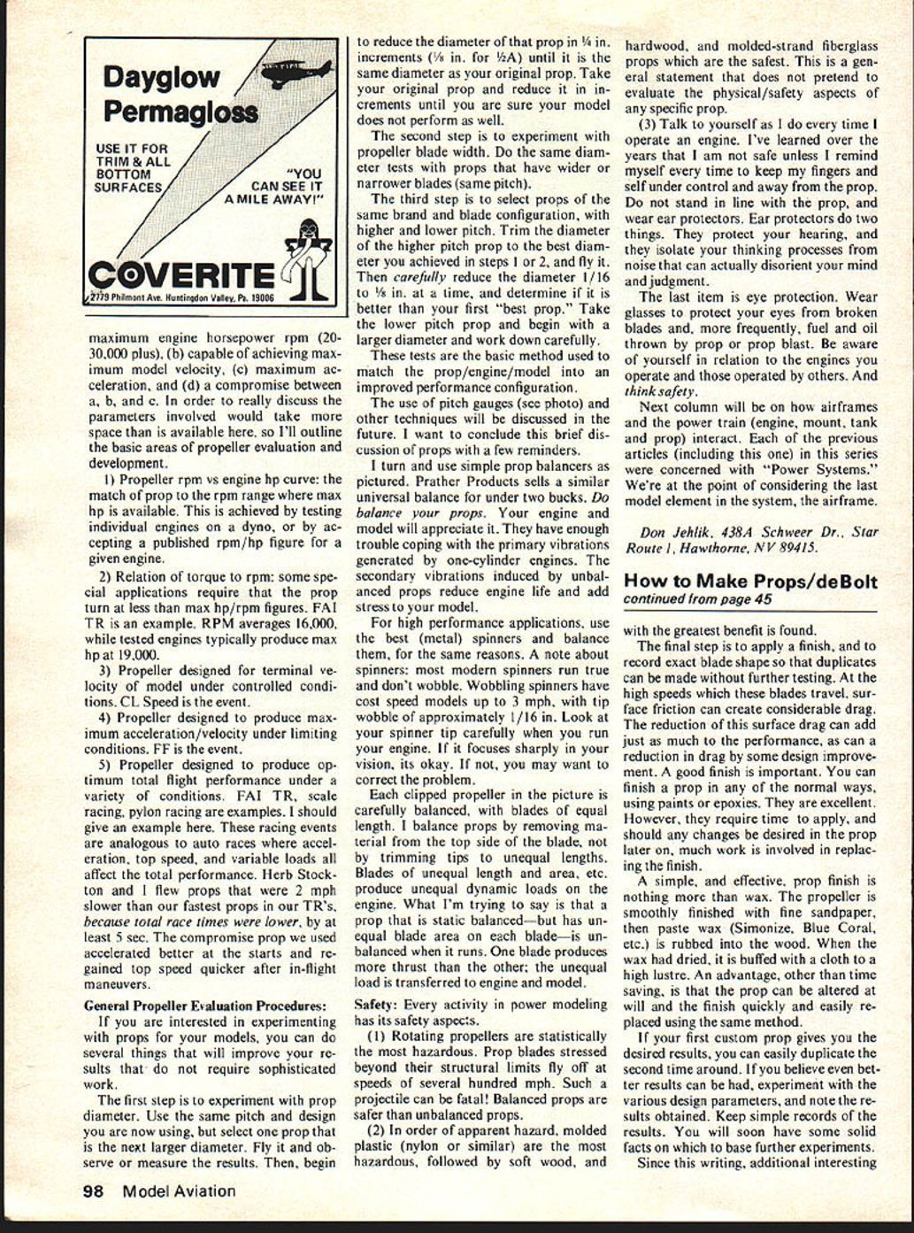
The second is Power and Performance Testing: The photo of the Bugl diesel engine shows three test props. Another photo shows an array of props cut to various sizes for hp tests. I do hp tests on a swing-weight dynamometer. The use of a series of props that place maximum to minimum practical loads on the engine, allows me to plot the power curve of the engine, as well as the engine response to different fuels, plugs, etc. This gets rather esoteric: I'll reserve a future article for that discussion.
A sensible use of special props is in the area of performance testing. Remember? I've said before that bench running is "where it's at" for the performance modeler. Briefly, performance testing is lots of things. That Bugl engine has three performance test props because: (a) one exactly duplicates the load placed on the engine in flight, (b) another allows the en
Engine Technique/Jehlik
gine to turn 19,000 rpm (3,000 over flight rpm) and, (c) the third prop is a "standard" that exactly matches the test prop Paul Bugl uses in his tests. From the three props I then am able to reproduce flight loads on the bench so I will be able to predict exactly how the engine will perform in the model (within 1 lap and 1 rpm!), and verify performance figures with another experimenter (Bugl). FAI Team Race performance testing is the most refined form of testing currently being done. The rapid advances in helicopter and ducted fan models are benefiting from similar experiments.
The development of appropriate props in performance testing will enable the modeler to predict performance: Racing events—laps and speed, CL aerobatics—engine response and duration of run, Throttled engines—engine response and throttle characteristics.
The third use for props is flying. It may seem odd to you that I think of flying props last. Really, all three uses of props are synergistic. I've put flight props last to impress upon you the importance of the break-in, and power and performance testing procedures. Flight props fall into several categories or applications. They will be discussed separately.
Moderate Performance Props are those used for sport flying and competition flying that does not place exacting demands on design, or match to engine power. Scale, precision aerobatics and sport flying are examples. The basic rule in selection of props here, (a) is to use props recommended by the engine manufacturer, (b) select from available props the one that best suits your requirements, and (c) stick to off-the-shelf props.
High Performance and Special Application Props are used in those events that involve high stresses and/or special design requirements to achieve optimum performance. Speed, racing events, combat, and high performance FF are events that place special demands on props. The demands typically are: (a) operate at maximum engine horsepower rpm (20-30,000 plus), (b) capable of achieving maximum model velocity, (c) maximum acceleration, and (d) a compromise between a, b, and c. In order to really discuss the parameters involved would take more space than is available here, so I'll outline the basic areas of propeller evaluation and development.
1) Propeller rpm vs engine hp curve: the match of prop to the rpm range where max hp is available. This is achieved by testing individual engines on a dyno, or by accepting a published rpm/hp figure for a given engine.
2) Relation of torque to rpm: some special applications require that the prop turn at less than max hp/rpm figures. FAI TR is an example. RPM averages 16,000, while tested engines typically produce max hp at 19,000.
3) Propeller designed for terminal velocity of model under controlled conditions. CL Speed is the event.
4) Propeller designed to produce maximum acceleration/velocity under limiting conditions. FF is the event.
5) Propeller designed to produce optimum total flight performance under a variety of conditions. FAI TR, scale racing, pylon racing are examples. I should give an example here. These racing events are analogous to auto races where acceleration, top speed, and variable loads all affect the total performance. Herb Stockton and I flew props that were 2 mph slower than our fastest props in our TRs, because total race times were lower, by at least 5 sec. The compromise prop we used accelerated better at the starts and regained top speed quicker after in-flight maneuvers.
General Propeller Evaluation Procedures:
If you are interested in experimenting with props for your models, you can do several things that will improve your results that do not require sophisticated work.
The first step is to experiment with prop diameter. Use the same pitch and design you are now using, but select one prop that is the next larger diameter. Fly it and observe or measure the results. Then, begin to reduce the diameter of that prop in 1/4 in. increments (1/8 in. for 1/2A) until it is the same diameter as your original prop. Take your original prop and reduce it in increments until you are sure your model does not perform as well.
The second step is to experiment with propeller blade width. Do the same diameter tests with props that have wider or narrower blades (same pitch).
The third step is to select props of the same brand and blade configuration, with higher and lower pitch. Trim the diameter of the higher pitch prop to the best diameter you achieved in steps 1 or 2, and fly it. Then carefully reduce the diameter 1/16 to 1/8 in. at a time, and determine if it is better than your first "best prop." Take the lower pitch prop and begin with a larger diameter and work down carefully.
These tests are the basic method used to match the prop/engine/model into an improved performance configuration.
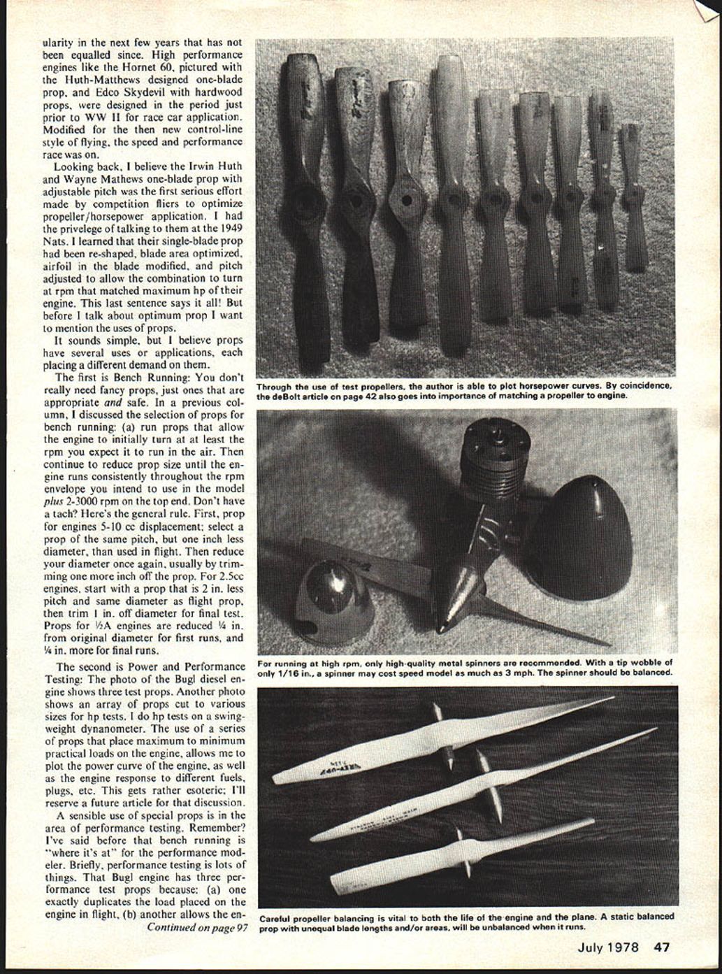
The use of pitch gauges (see photo) and other techniques will be discussed in the future. I want to conclude this brief discussion of props with a few reminders.
I turn and use simple prop balancers as pictured. Prather Products sells a similar universal balance for under two bucks. Do balance your props. Your engine and model will appreciate it. They have enough trouble coping with the primary vibrations generated by one-cylinder engines. The secondary vibrations induced by unbalanced props reduce engine life and add stress to your model.
For high performance applications, use the best (metal) spinners and balance them, for the same reasons. A note about spinners: most modern spinners run true and don't wobble. Wobbling spinners have cost speed models up to 3 mph, with tip wobble of approximately 1/16 in. Look at your spinner tip carefully when you run your engine. If it focuses sharply in your vision, it's okay. If not, you may want to correct the problem.
Each clipped propeller in the picture is carefully balanced, with blades of equal length. I balance props by removing material from the top side of the blade, not by trimming tips to unequal lengths. Blades of unequal length and area, etc., produce unequal dynamic loads on the engine. What I'm trying to say is that a prop that is static balanced—but has unequal blade area on each blade—is unbalanced when it runs. One blade produces more thrust than the other; the unequal load is transferred to engine and model.
Safety: Every activity in power modeling has its safety aspects.
- Rotating propellers are statistically the most hazardous. Prop blades stressed beyond their structural limits fly off at speeds of several hundred mph. Such a projectile can be fatal! Balanced props are safer than unbalanced props.
- In order of apparent hazard, molded plastic (nylon or similar) are the most hazardous, followed by soft wood, and molded-strand fiberglass props which are the safest. This is a general statement that does not pretend to evaluate the physical/safety aspects of any specific prop.
- Talk to yourself as I do every time I operate an engine. I've learned over the years that I am not safe unless I remind myself every time to keep my fingers and self under control and away from the prop. Do not stand in line with the prop, and wear ear protectors. Ear protectors do two things. They protect your hearing, and they isolate your thinking processes from noise that can actually disorient your mind and judgment.
The last item is eye protection. Wear glasses to protect your eyes from broken blades and, more frequently, fuel and oil thrown by prop or prop blast. Be aware of yourself in relation to the engines you operate and those operated by others. And think safety.
Next column will be on how airframes and the power train (engine, mount, tank and prop) interact. Each of the previous articles (including this one) in this series were concerned with "Power Systems." We're at the point of considering the last model element in the system, the airframe.
Don Jehlick, 438A Schweer Dr., Star Route 1, Hawthorne, NV 89415.
Transcribed from original scans by AI. Minor OCR errors may remain.

