
Envoy
Allen W. Brickhaus
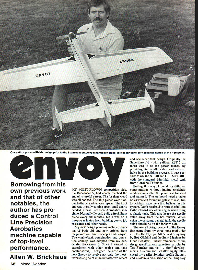
Borrowing from his own previous work and that of other notables, the author has produced a Control Line Precision Aerobatics machine capable of top-level performance.
Introduction
My most-flown competition ship, the Buccaneer 5, had nearly reached the end of its useful career. The fuselage was oil-soaked and the ship had gained over 6 oz. due to oil and various repairs. The front end was literally coming apart, and I needed a new Precision Aerobatics machine. Normally I build a fresh stunt plane every six months to a year, but a three-year hiatus from building—caused by job pressures and other needs—delayed this.
My new design planning included reading both old and recent articles on stunt concepts and designs. I borrowed concepts and details from a number of sources and incorporated features that had worked well for me in the past.
Design influences and overall concept
The overall design concept of the Envoy was influenced primarily by:
- Olympic Mk VI and Sting Ray (Bob Gialdini)
- Stunt Machine (Gene Schaffer)
- Developments by Ted Fancher
- My previous designs (Buccaneer 5, Scimitar)
From these sources I decided on several key features:
- A thicker wing for better lift with a blunt leading edge to prevent early airflow separation.
- A tip airfoil thicker than the root and placed slightly forward of the root’s thickest section to delay tip stalls and add stability in turns and level-flight tracking.
- A swept-forward flap configuration (1 in. forward sweep chosen after trials) to help keep the center of lift from moving too far aft relative to the center of gravity.
- Slightly larger flaps than the Olympic Mk VI: 13.5% of total wing area (Olympic Mk VI used 12%) to compensate for heavier expected weight.
I designed the nose to accept multiple engine and tank combinations so I could experiment without unsightly modifications after finishing and painting. Originally the Supertigre .46 with a Sullivan RST 6-oz. tank was intended, but the nose was made to accept that plus an ST .40, an O.S. Max .40H, and a standard 1-in.-high metal tank from Carolina-Taffinder.
Notes on needle valve placement:
- For plastic tanks: outboard needle-valve holes can be used; route the fuel line to the inboard side of the engine to keep the needle away from a hot muffler.
- For metal tanks: the needle valve should be on the inboard side.
Wing, flaps and tail
I wanted foam wings and flaps and examined many recent designs. Ted Fancher’s Excitation wing (about 650 sq. in.) suited my needs with only small flap-length changes noted on the plans.
Key dimensions and percentages:
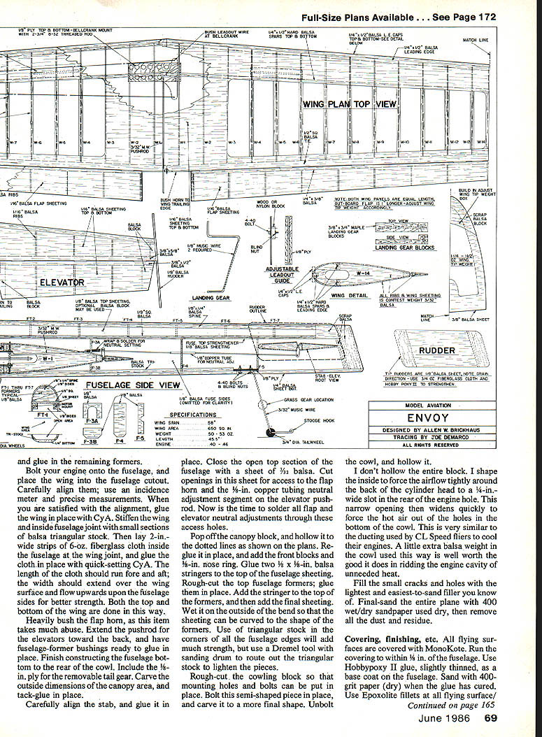
- Wing area: ~650 sq. in.
- Flaps: ~13.5% of total wing area
- Horizontal tail: stab/elevator is 23.5% of the horizontal tail area
- Elevator: 47% of the stabilizer
- Thickness percentages for airfoils were taken from Norm Whittle’s Eagle V design; the modified wedge-shaped airfoil eases construction.
Parts availability:
- The Envoy wing, flaps, stab and elevators (foam) can be purchased from Par Troy Sound. Contact Mark Salvador at Sussex Co. Mall, Rt. 94, Newton, NJ 07860. Ask for the Excitation wing and flaps plus the stab and elevators of Norm Whittle’s Eagle V. (The Eagle V tail assembly has more of a true airfoil than the wedge-shaped tail drawn on the plans; both work well.)
Although the Envoy can be built with all-foam flying surfaces, the plans also show built-up structures for those who prefer framework construction.
Landing gear and practice configurations
My wing and flap foam cores were cut with a spar glued in place and false plywood ribs for attaching wing-mounted landing gear blocks. Both wing and tail gear are removable. I use two gear sets depending on surface:
- Grass (practice): larger lightweight wheels, mounted a bit forward, and a very short tail gear.
- Hard surfaces (contest): smaller wheels with fairings and a longer tail gear.
If you prefer main gear mounted in the fuselage, bolt a 3/8-in. music wire on the back side of the former at the wing/fuselage joint and cut away the wing leading edge where needed to position the gear close to the wing.
Construction
Wing and flaps
- Foam cores arrive as left and right panels; purchase with the spar and the two front ribs per panel for secure gear mounting.
- When gluing wing sheeting, run the grain parallel to the leading edge until the aft portion that will cover the flap hinge line. Then cut and glue sheeting to run parallel to the hinge line so you don’t cut across the grain when removing flaps.
- Determine and mark the flap hinge line on top and bottom of the wing. Draw parallel pencil lines 1/4 in. forward and 1/4 in. aft of that line. Cut away the flaps at the fore and aft pencil lines.
- Glue 1/8-in. balsa to the trailing edge of the wing and to the leading edge of the flaps.
- Glue 1/8-in. balsa ribs to the wing tips before adding the actual tips to keep the airfoil shape true for covering.
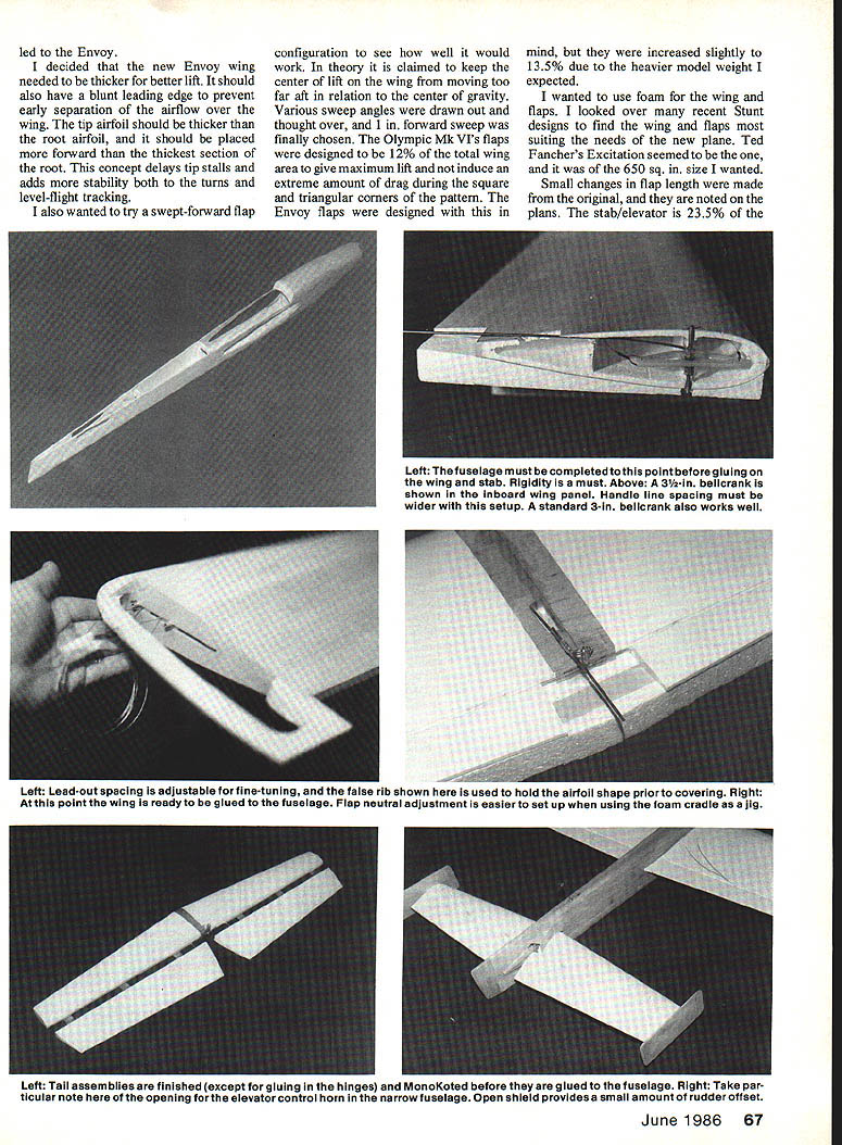
- Join cores together with 15-min. epoxy, then glue on the actual tips, lead-out guide, weight box, and flap horn.
- Install a well-bushed control system. A Klett PEG-1 pushrod exit guide is glued to the wing tip at the lead-out slot to strengthen the slot after covering.
- Measure and mark lead-out lines to determine the bellcrank neutral setting while cores are assembled.
Fuselage
- Mark reference lines on your building board to align sides and formers while gluing.
- Glue fuselage doublers to the sides with 5-min. epoxy. Glue engine mount blocks with slow-setting cyanoacrylate (CyA) to the fuselage doublers.
- Set F-1 and F-2 in place, pin sides to the board, align and glue. Glue the aft end and remaining formers in place.
- Bolt engine to the fuselage and place the wing into the fuselage cutout. Carefully align using an incidence meter and precise measurements. When aligned, glue the wing in place with CyA.
- Stiffen the wing/fuselage joint with small sections of balsa triangular stock. Then lay 2-in.-wide strips of 6-oz. fiberglass cloth inside the fuselage at the wing joint and glue them in place with quick-setting CyA. Cloth should run fore-and-aft and extend over the wing surface and up the fuselage sides; do both top and bottom of the wing joint.
- Heavily bush the flap horn; it takes much abuse.
- Extend the elevator pushrod toward the rear and install fuselage-former bushings.
- Finish the fuselage bottom to the rear of the cowl; include 1/8-in. plywood for the removable tail gear.
- Carve the canopy area and tack-glue the canopy block in place. Carefully align and glue the stab. Close the open top of the fuselage with 3/32-in. balsa sheet and cut openings for access to the flap horn and the 1/8-in. copper tubing neutral adjustment segment on the elevator pushrod. Solder flap and elevator neutral adjustments through these access holes.
- Pop off the canopy block, hollow it to the dotted lines on the plans, reglue, and add front blocks and a 1/8-in. nose ring.
- Glue two 1/8 x 1/8-in. balsa stringers to the top fuselage sheeting. Rough-cut and glue top fuselage formers, add the stringer and final sheeting. Wet the sheet on the outside of the bend so it curves to the formers’ shape.
- Use triangular stock in fuselage corners for strength; route out triangular stock with a Dremel sanding drum to lighten parts.
- Rough-cut cowling block, bolt in place to fit mounting holes and bolts, carve to final shape, then unbolt and hollow.
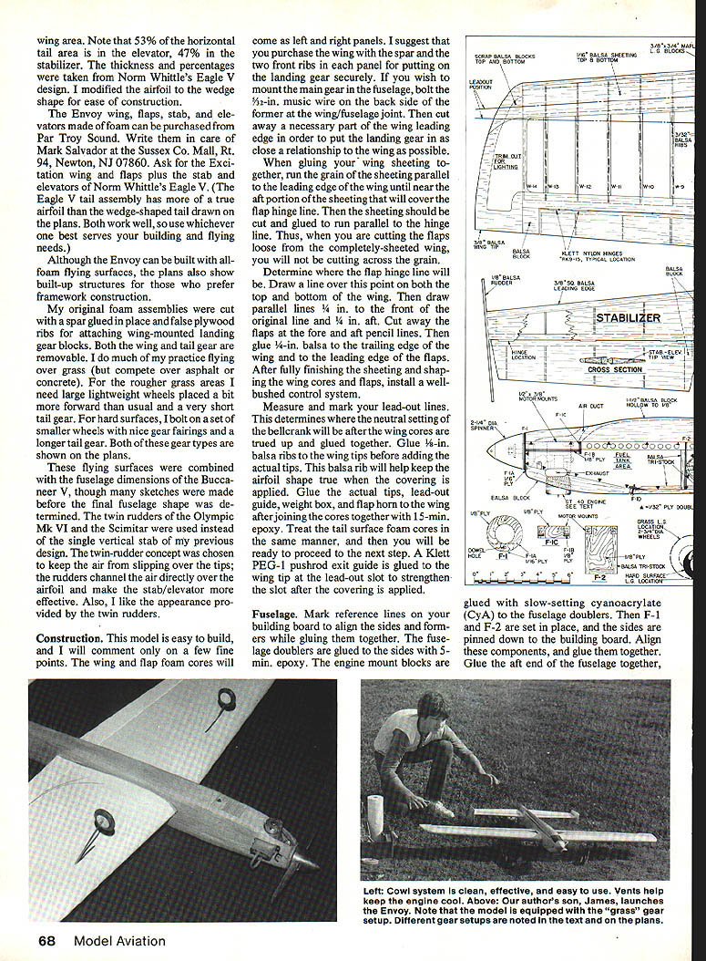
Cowl airflow note:
- I don’t hollow the entire block. Shape the inside to force airflow lightly around the back of the cylinder head to a 1/4-in.-wide slot at the rear of the engine hole; this then widens quickly to force hot air out of holes in the bottom of the cowl. This ducting is similar to CL speed setups and helps rid the engine cavity of excess heat. A little extra balsa weight in the cowl is worth the cooling benefits.
Finishing construction steps
- Fill small cracks and holes with an easy-to-sand filler. Final-sand the entire plane with 400-grit paper. When glue has cured, use Epoxolite fillets at all flying surface joints.
Covering and painting
- Cover all flying surfaces with MonoKote and run the covering to within 1/8 in. of the fuselage.
- Use Hobbypoxy II (slightly thinned) as a base coat on the fuselage. Sand with 400-grit (dry) when cured.
- Apply Epoxolite fillets at flying surface/fuselage joints, flowing the fillets over the edge of the plastic covering to seal edges and prevent fuel leakage into porous balsa.
- Mask off wing and stab and brush on a slightly thinned coat of Stuff by Hobbypoxy. Sand with 240-grit to prepare for painting.
- Mask and prime with Rustoleum gloss clear, then spray one dusted-on layer of Rustoleum gloss white and a heavier wet coat one hour later.
- I paint the bottom trim first to learn masking characteristics and paint drying times. Top wing surfaces next. The fuselage top takes three maskings: black anti-glare panel first, windshield second, and fuselage back last. Add the name (Envoy) and AMA numbers.
Final assembly and setup
- Glue flaps and elevators in place.
- Bolt on whichever landing gear you will use and make up lead-out rods.
- Add weight to the wing tip box so the outer wing tip drops when the model is held by the spinner point and end of the center rudder. Set the balance point at least 1/4 in. forward of the point noted on the plans.
- Ensure flaps and elevators do not bind.
- Use clean fuel and a new, clean fuel filter. Engine should be well broken-in before flying in the Envoy.
- Mount the fuel tank firmly in the fuselage. I use folded foam pieces to keep the tank secure and prevent vibration. Tank vibration bubbles the fuel and causes an uneven mixture— a major source of running problems.
Recommended hardware, props and rigging
- Typical engine: Super Tigre .46 (stock venturi .161 in. dia.) with Sullivan RST 6-oz. tank (or alternatives noted earlier).
- Propellers: Rev-Up 10-6EW or Rev-Up 12-6.
- Release rpm: ~8,250 rpm on a Royal tachometer (12-6 tends to hold ~8,250; 10-6EW may show tach bouncing toward ~8,500).
- Lap times: about 5.5 to 5.7 seconds with the setup described.
- Muffler: shortened DuBro stack with a plate bolted to the exhaust end; four 5/32-in. holes drilled for exhaust. Use a Harry Higley Big Taper for muffler pressure to tank.
- Lines: .018-in. stranded cable, 64 ft. long measured eyelet to eyelet.
- Handle spacing: equivalent to the stock EZ-Jr small handle. I found a 6-in. handle superior to a 7-in. for my preference; adjust for different handles and overhangs by measuring from handle center/hand to lead-out exit.
Note: Any change in weight, prop, venturi or line lengths will affect number of laps and lap time. If the plane weighs more (e.g., 60 oz.), adjust other parameters to maintain controllability through the pattern.
Fuel and engine running notes
I experienced persistent engine-run problems early in a season, ruining two engines and possibly damaging a third ring/cylinder seal. After trying tank and line cleaning and different props, the turning point came when Tom Dixon at Lexington gave me all-castor-oil fuel. Prior to that I had been using club fuel that was half castor and half synthetic—fine for RC engines running higher rpm where heat dissipates better, but when loading Stunt engines (heavier planes, bigger props, slower rpm), heat buildup is significant.
All-castor fuel performed much better for my loads and generally solved 95% of my lean-run problems last year. If your engine runs lean and you have checked the usual items, verify the tank will hold fuel in the vertical position—if it doesn’t, the clunk may draw air even with a seemingly full tank.
I used both plastic and metal tanks successfully as long as they are set up for uniflow and muffler pressure. Typically, 5 oz. of fuel are consumed for a full pattern, and I usually complete another 10–12 laps after exiting the cloverleaf.
Performance and contest experience
With the Envoy setup described (650 sq. in. wing, trim weight ~53–56 oz., Super Tigre .46), I achieved:
- Release rpm ~8,250
- Lap times ~5.5–5.7 sec.
- Consistent competition success: three first places in a row at Lexington, Atlanta, and Rockford, IL.
Unfortunately, the Envoy was lost in a crash on the last flight at Rockford due to gusty winds (~25 mph) that caught the plane during the cloverleaf. A new Envoy is being constructed with very few changes from the first.
Some building/flying tips and reminders
- Don’t be afraid to route fuel lines inboard when using plastic tanks—this keeps the needle valve away from the muffler.
- Heavily bush the flap horn and use good bushing at pushrod exits.
- Use folded foam to secure the tank and prevent vibration.
- Break in engines thoroughly before serious flying.
- Balance the wing properly and ensure controls are free.
- Try all-castor fuel if you experience unexplained lean runs in loaded, low-rpm Stunt setups.
Conclusion
I hope this article and the Envoy design help you increase your interest and activity in control-line precision aerobatics. Nothing here is etched in stone—I will make changes as problems are discovered and solved. Join PAMPA and fly a few contests even if you’re not an expert; every expert began as a novice. Enjoy the sport, and the time and activity will improve your flying and building expertise.
Transcribed from original scans by AI. Minor OCR errors may remain.

