

Europa
- Terry D. Edmonds
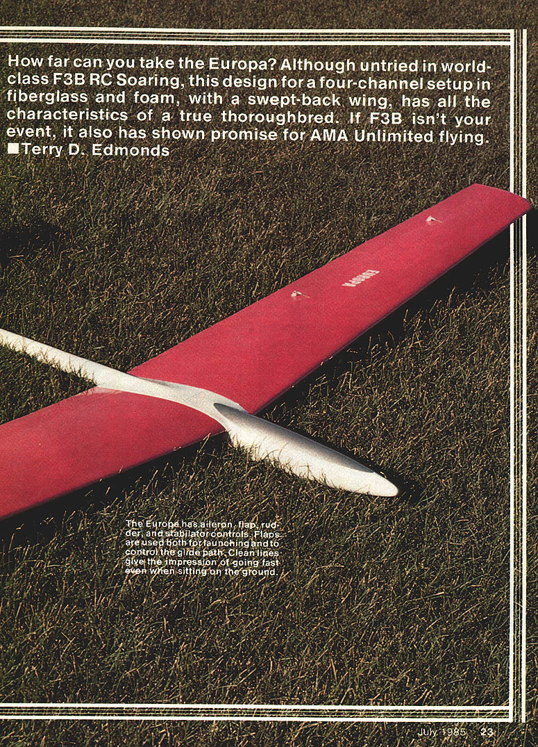
How far can you take the Europa? Although untried in world-class F3B RC soaring, this four‑channel design in fiberglass and foam, with a swept‑back wing, has the characteristics of a true thoroughbred. If F3B isn't your event, it has also shown promise for AMA Unlimited flying.
This sailplane was conceived as a state‑of‑the‑art design for F3B competition. It combines European and American features with some unique touches to produce a highly competitive F3B machine. Foam and fiberglass technology are used for an extremely strong structure that can handle powerful winches while maintaining a moderate empty weight. The unballasted wing loading is about 11.5 oz./sq. ft. The fiberglass fuselage and foam wing cores are being made commercially available at a nominal cost to assist the average modeler in reproducing the sailplane.
I should state up front that I have not competed in world‑class F3B competition or American team trials. However, this plane/pilot combination placed 3rd in F3B speed at the 1983 LSF International Tournament in Chicago and 2nd in F3B at the 1984 Nationals in Reno. I believe the design has potential far beyond its present accomplishments.
The current F3B rules emphasize the speed task. Speed is the only task one can potentially win outright, since the best possible duration or distance scores often tie. The Eppler 205 airfoil was chosen for the Europa with speed in mind, though many good airfoils could also work. Airfoil choice produces relatively small differences in overall performance; consistently high launches and pilot/plane experience are of primary importance. Zoom launches are executed well by the Europa; it has been launched on some of the most powerful winches in the country without folding a wing to the ground (although wing breakage is always possible and difficult to predict).
The Europa wing has a mild sweepback. Testing indicates the sweep yields an effective dihedral increase, improving turning characteristics. Sweep also has the psychological effect of appearing to move faster.
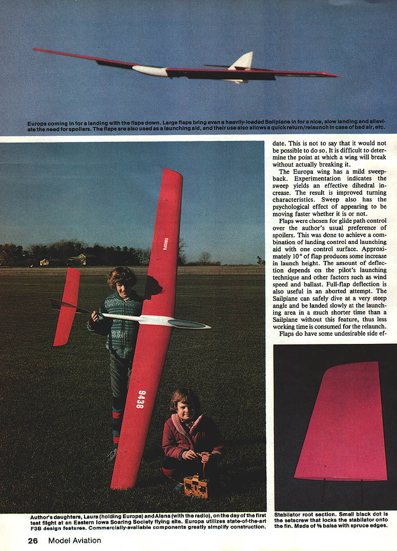
Flaps were chosen for glide‑path control over my usual preference for spoilers to achieve a combination of landing control and a launching aid with one control surface. Approximately 10° of flap produces some increase in launch height; the amount depends on pilot technique, wind, and ballast. Full‑flap deflection is useful in aborted attempts—the sailplane can safely dive at a very steep angle and be landed slowly at the launch area in much less time than a sailplane without this feature, reducing relaunch working time.
Flaps do have undesirable side effects:
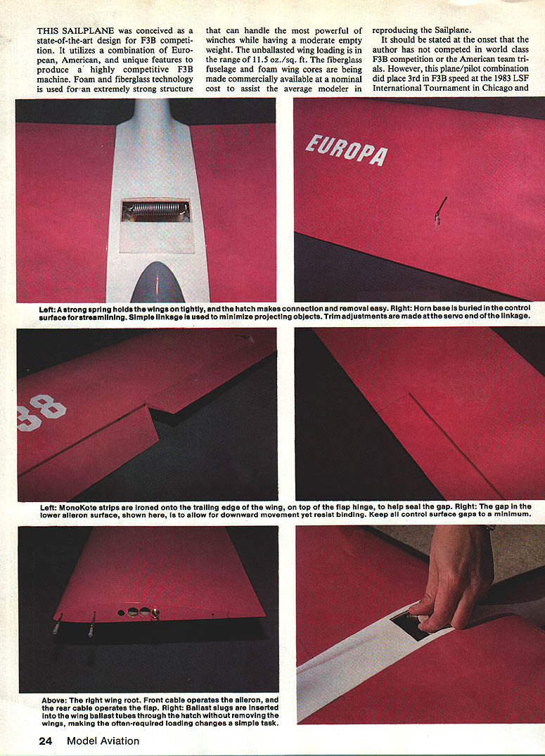
- Additional drag is created at the hinge line; sealing the gaps minimizes this effect. I use MonoKote seals.
- A pitch‑up effect when flaps are deflected is significant enough that a mixer to correct stabilizer trim is necessary (an electronic mixer in the transmitter or a mechanical mixer in the plane can be used).
- A "pancake" effect can occur when retracting flaps at slow speed; overcome this by using a slightly higher landing speed.
Ailerons and rudder are driven by independent servos. I use an electronic coupler in my transmitter to couple and uncouple the ailerons and rudder in flight. An alternative is to couple them continuously by connecting both servos to the aileron channel with a Y‑harness.
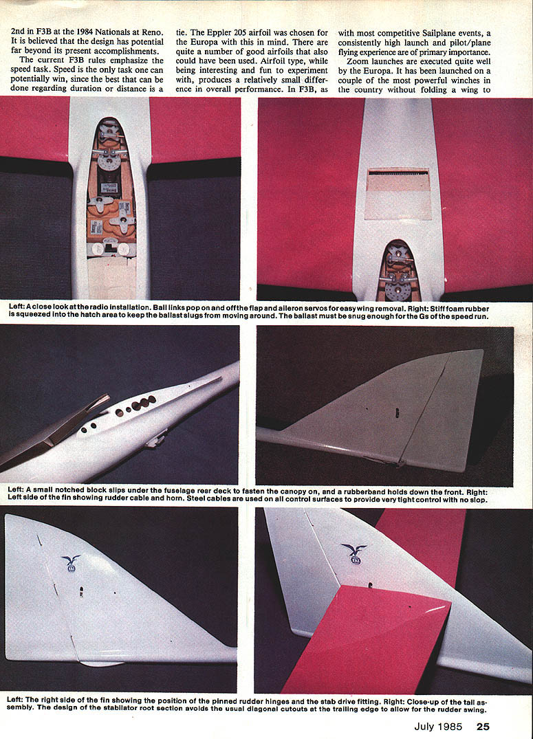
The stabilator is quite thin; while that might suggest pitch sensitivity, flight testing has not shown a problem. The stabilator root section does not extend aft of the rudder hinge line, avoiding the usual diagonal cutout in the stabilator trailing edge to allow rudder swing.
Direct‑drive steel control cables are used to all control surfaces to discourage flutter from floppy linkages. Choose cables that fit closely to the outer tubing to avoid slop at 90° bends. Flaps and ailerons are driven near the center of their span to lessen the possibility of flutter.
Ballast is carried in the wing to keep the fuselage small. The ballast tubes can hold up to 5.6 lb. of ballast; filling them to capacity would raise the Europa wing loading to slightly over the F3B limit. Being able to change ballast quickly is important, particularly if you do it on working time. To avoid removing the wings each time, an access hatch is provided on top of the fuselage. Ballast is 1/2 x 2‑in. brass tubes filled with lead (see the Callisto ’82 article, October 1982 Model Aviation). When using ballast, a tube is completely filled with ballast (or ballast plus dowel dummy slugs) and held in place by a stiff piece of foam squeezed into the hatch area.
At first I thought the Europa would not be good for AMA Unlimited duration events because of its weight. Early trials were not particularly successful, but I later discovered the plane requires a different piloting technique than a lighter ship. In windy conditions the Europa actually has advantages: lighter planes need to add ballast to match the Europa's wing loading, while the Europa has superior strength and is designed for higher airspeeds. Building a lighter weight version specifically for duration events has also been considered.
Construction
It is expected builders choosing the Europa for F3B have a reasonable amount of construction experience. Experienced modelers often have their own techniques and may make design modifications, so the following are general building notes rather than step‑by‑step instructions.
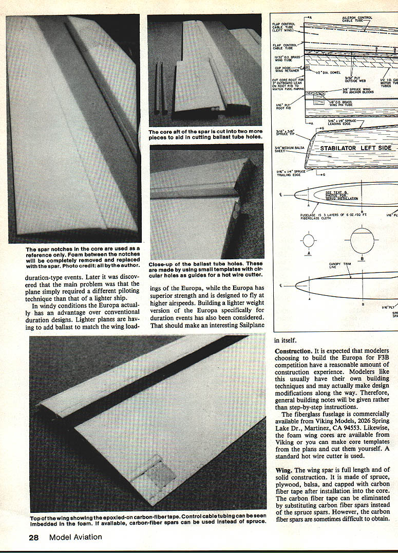
The fiberglass fuselage is commercially available from Viking Models, 2026 Spring Lake Dr., Martinez, CA 94553. Foam wing cores are available from Viking, or you can make core templates from the plans and cut them yourself with a standard hot‑wire cutter.
Wing
- The wing spar is full length and of solid construction, made from spruce, plywood, balsa, and capped with carbon fiber tape after installation into the core. The carbon tape can be omitted by substituting carbon fiber spars for the spruce spars, though carbon spars can be hard to obtain.
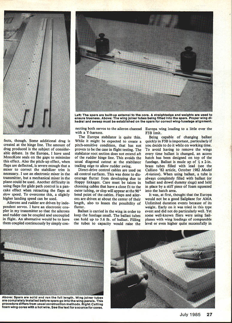
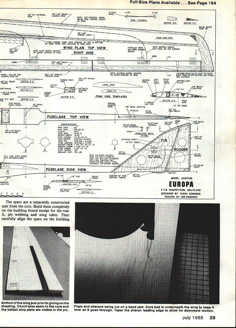
- The spars are built separately from the core. Complete them on the building board except for the rear 3/32" ply webbing and wing tubes, then carefully align the spars on the board.
- With the proper dihedral and sweepback, a single length of brass wing tube is fitted in the cavities. Some hollowing of the 1/2‑ply webbing may be necessary for proper fit. Install the rear webbing while filling the cavity with microballoons and epoxy. Cut the tubing off about 1/16 in. beyond the end of the spars.
- The core must be cut into two pieces for the spar to be installed. The spar notches in core templates are only reference; the whole area between the notches is eventually cut out. This is also when to cut cavities for the ballast tubes. One method is to cut the core piece aft of the spar into two pieces at the end of the ballast tubes, perpendicular to the trailing edge, then cut the cavities with a hot‑wire cutter using small tangent‑circle templates.
- Epoxy the core pieces and spar together at one time, place back into the core beds, and weigh down until cured. Epoxy carbon fiber tape on top and bottom of the core over the spars.
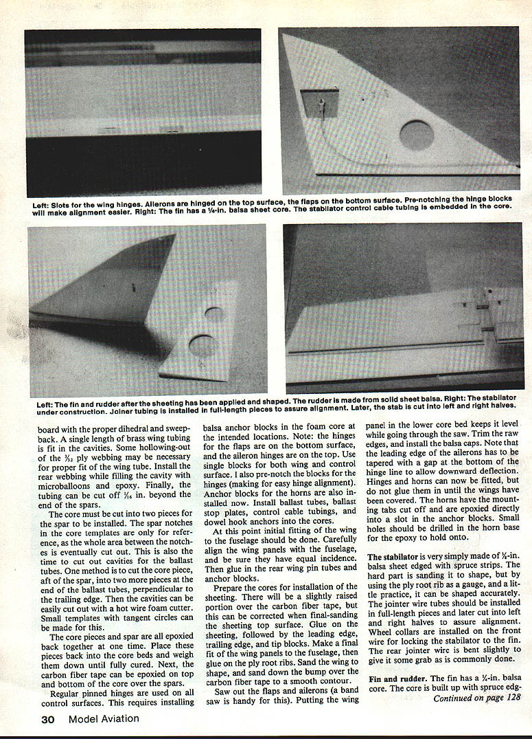
- Install balsa anchor blocks in the foam core where pinned hinges will go (hinges for the flaps are on the bottom surface, aileron hinges on the top). Pre‑notch the blocks for easy hinge alignment. Install anchor blocks for horns, ballast tubes, ballast stop plates, control cable tubing, and dowel hook anchors.
- Initially fit the wing to the fuselage, carefully aligning panels and ensuring equal incidence. Glue in the rear wing pin tubes and anchor blocks.
- Prepare cores for sheeting—there may be a slightly raised portion over the carbon tape that can be corrected during final sanding. Glue on sheeting, then install leading edge, trailing edge, and tip blocks. Fit the wing panels to the fuselage and glue on the ply root ribs. Sand the wing to shape and smooth the bump over the carbon fiber tape.
- Saw out the flaps and ailerons (a band saw is helpful). Put the wing panel in the lower core bed to keep it level while sawing. Trim raw edges and install balsa caps. The aileron leading edge must be tapered with a gap at the bottom of the hinge line to allow downward deflection. Fit hinges and horns but do not glue them in until after covering. Cut the horns' mounting tabs off and epoxy the horn base directly into a slot in the anchor blocks; drill small holes in the horn base for epoxy anchoring.
Stabilator, Fin and Rudder
- The stabilator is made from 1/8‑in. balsa sheet edged with spruce strips. Sanding to shape is the hardest part; use the ply root rib as a gauge. Install the joiner wire tubes as full‑length pieces, then cut into left and right halves to assure alignment. Install wheel collars on the front wire to lock the stabilator to the fin. The rear joiner wire is bent slightly to provide a grab as commonly done.
- The fin has a 1/4‑in. balsa core; the rudder is made from solid sheet balsa. Use steel cables on the control surfaces for tight, slop‑free control. Position‑pin the rudder hinges and fit the stab drive fitting and cable runs.
- The stabilator root section avoids diagonal cutouts in the trailing edge to allow rudder swing.
- Make up the hinge pieces, ply insert, and control cable tubing. Install the stab drive fitting. Cut a 1/4‑in. slot in the top of the fuselage tail boom and fit the fin core in position. Mark where the tip of the boom lies on the fin sides and glue on the 1/16‑in. balsa fin side sheeting from the marks up. Build up the rudder, then sand fin and rudder to shape. Use pinned hinges on the rudder fitted with no hinge‑line gap.
Fuselage
- Cut an opening in the top for an access hatch and construct a small frame around the inside edges. Make a hatch cover from balsa and attach it with small brass piano hinges.
- The wing rod tube in the fuselage should have been glued in during wing fitting. Use plywood, spruce, and a microballoons/epoxy mixture for additional support of the wing into the fuselage as needed.
- Glue the fin into the fuselage tail boom while the wing panels are installed, making certain the fin is perpendicular to the wing. It may help to have the stabilator on while doing this. Secure control cable tubes in the fuselage along their entire length, or at least as much as possible—high‑speed maneuvering can cause unsupported tubes to distort and interfere with control.
Before using large flap deflections, be aware it is easy to use too much flap and actually decrease performance rather than increase it.
The Europa can also be successfully launched on a high‑start. Use only a heavy‑duty high‑start and stretch it to a minimum pull of 12 lb, as the Europa is not a light airplane.
Speed runs should first be flown without ballast to get the feel of the ship. Slowly add ballast to find the highest speed point. Keep the nose down in turns to avoid losing momentum. Split‑S turns are effective on turns one and two—practice these at altitude first. Zoom launches are executed quite well; the Europa has launched on several powerful winches around the country.
Finish
- Use MonoKote for all wood surfaces and K&B paint for the fuselage. Other finishes are possible, but avoid unnecessary finish weight—F3B models tend to be relatively heavy without adding excess finish.
Installation
- If the flap and aileron cables were installed as per the plans, the servo arrangement will need to be close to that shown in the photographs. Kraft KPS‑24 servos were used in the prototype for their high torque and tight centering.
- The aileron and flap servos are in‑line; the rudder and stabilator servos are across. Mount the in‑line servos on a plywood tray for easier installation and removal; mount the other servos on rails.
- Use ball links to attach flap and aileron linkage. Links are snapped on with the forefinger and easily unsnapped by placing a small flat‑blade screwdriver under the link and twisting. Aileron differential is adjusted by the take‑off point on the servo wheel.
Flying
- Hand‑toss the model a few times to check control sensitivity.
- Hook it on the winch and build up a fairly large spring tension before launching.
- Become familiar with the Europa before using the flaps extensively.
Transcribed from original scans by AI. Minor OCR errors may remain.

