
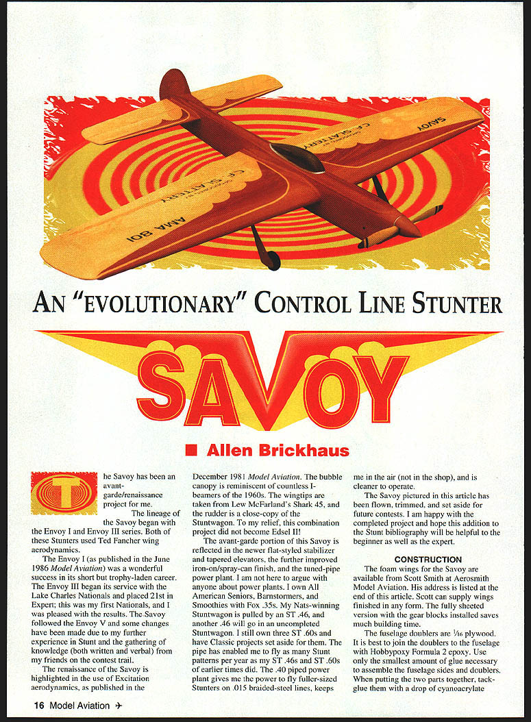
An "EVOLUTIONARY" Control Line Stunter: SAVOY
Allen Brickhaus
The Savoy has been an avant-garde/renaissance project for me. Its lineage began with the Envoy I and Envoy III series, both of which used Ted Fancher wing aerodynamics. The Envoy I (published in the June 1986 Model Aviation) enjoyed a short but trophy‑laden career. The Envoy III began service at the Lake Charles Nationals and placed 21st in Expert — my first Nationals.
The Savoy followed the Envoy V and incorporates changes from further contest experience and knowledge gathered from friends on the contest trail. The renaissance aspects include the use of "Excitation" aerodynamics (December 1981 Model Aviation). The bubble canopy recalls I‑beamers of the 1960s, the wingtips are from Lew McFarland's Shark 45, and the rudder closely copies the Stuntwagon. The avant‑garde features include a flat‑styled stabilizer with tapered elevators, an improved iron‑on/spray‑can finish, and a tuned‑pipe power plant. The Savoy pictured here has been flown, trimmed, and set aside for future contests; I hope it will be helpful to both beginners and experts.
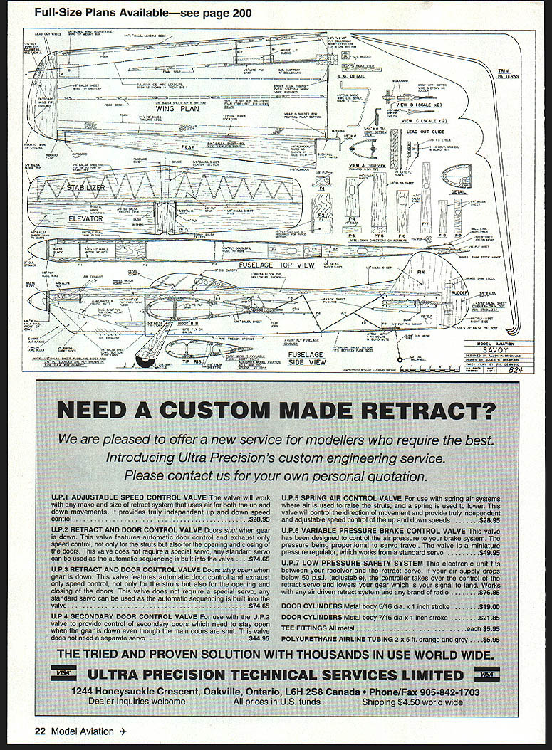
SAVOY (SPECIFICATIONS)
- Type: CL Stunt
- Wingspan: 63-1/2 inches
- Wing area: 665 square inches
- Power: Precision Aero .40 (or equivalent) on pipe
- Flying weight: 61-1/2 ounces
- Construction: Foam wing, built‑up fuselage and balsa sheet
- Covering/Finish: Iron‑on film, fiberglass cloth
CONSTRUCTION
Wings
- Foam wings for the Savoy are available from Scott Smith at Aerosmith Model Aviation. He can supply wings in any finished form; a fully sheeted version with gear blocks installed saves much building time.
Fuselage doublers
- Use 1/16" plywood doublers joined to the fuselage with Hobbypoxy Formula 2 epoxy. Use the smallest amount of epoxy necessary.
- When assembling, tack the parts with a drop of cyanoacrylate (CyA) at the four corners to prevent sliding while the epoxy cures.
- 1/32" balsa doublers also work and are slightly lighter; they make fairing the spinner nose easier. A half‑ounce carbon fiber mat can be used between two balsa parts, bonded with Hobbypoxy Formula 2 and tacked like the plywood version. Choose the doubler material you prefer—both work fine.
Doubler extension and pipe trench
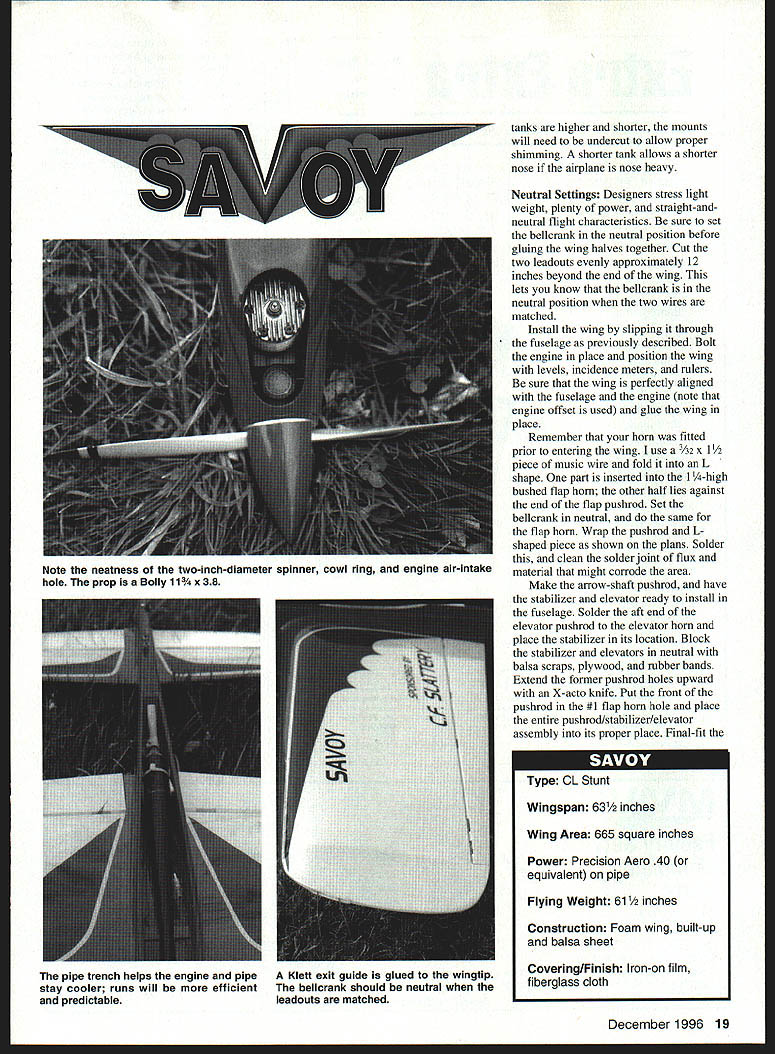
- Note how far the doubler extends past the wing: it dampens vibration and forms the bottom pipe trench. The trench keeps the tuned pipe cooler, more efficient and predictable, and makes in‑season pipe adjustments (often about 1/8") easier.
Wing‑to‑fuselage mating
- Slip the wing through the wing cutout in the inboard fuselage side when mating wing and body.
- Remove a small triangular section of the fuselage side if needed to route the pushrod; this piece can be reglued later.
- Fit the horn before slipping the wing in place so the wing jams horn bearings between the fuselage side and the wing trailing edge. The pushrod horn can be joined later.
- Set neutral control positions necessary for proper flying trim before final gluing.
Formers, cowl and fit
- Except for the upper pipe‑trench section (F1 and F2), make fuselage formers from 1/16" balsa. Observe grain direction for each piece.
- Slightly overcut the A6 balsa former and final‑sand the sides, top and bottom until it fits snugly; tight, slightly overstressed fits help insure a straight fuselage.
- The cowl bottom fits between the cowl sides and helps hold the cowl in place. Set the rear cowl forward face (F2) and cowl sides to conform to the inside of the fuselage doublers so they flush‑fit.
- Glue the cowl hold‑down plywood to the insides of the cowl sides so it freely extends upward between the fuselage sides. Fit the cowl sides tightly, hold components with pins and spot glue, add the cowl bottom and front block, and hold the assembly to the fuselage with masking tape while finalizing.
Cowl mounting and blind nut
- Drill a 3/32" hole through the fuselage side and 1/16" plywood doubler for the cowl hold‑down plywood. Remove the cowl and insert a 4‑40 blind‑mounting nut in the cowl hold‑down plywood with the nut facing outward. Make any drillings necessary to allow a 4‑40 socket‑head bolt to pass through the fuselage side, stop at the doubler, and engage the blind nut against the inside of the fuselage sides. Final‑sand the outer contours of the nose area and add the fuselage nose ring and cowl half ring.
Engine area and mounts
- The 3/16" aluminum pad at the engine area is secured at the rear by the F1 former; the front is screwed down with a #2 x 1/2" self‑tapping socket‑head screw. Epoxy the aluminum in place prior to finalizing F1 and the self‑tapping screw.
- Undercut the engine mounts to permit use of a plastic tank if desired and to accommodate varying tank spacing—slot the engine mount holes slightly for this purpose. Final‑fit the tanks; if tanks are higher and shorter, mounts will need more undercutting to allow proper shimming. A shorter tank allows a shorter nose if the model is nose heavy.
Neutral settings
- Designers stress light weight, plenty of power, and straight, neutral flight characteristics. Set the bellcrank in the neutral position before gluing the wing halves together.
- Cut the two leadouts evenly to about 12 inches beyond the wing tip to confirm the bellcrank neutral (matching wires indicates neutral).
- Install the wing (slip through the fuselage), bolt the engine in place, and use levels/incidence meters/rulers to align the wing perfectly with the fuselage and engine (note engine offset if used) before gluing.
- Fit the horn prior to wing installation. I use 3/32" x 1-1/2" music wire bent L‑shaped: one leg inserts into the 1/4"‑high bushed flap horn and the other lies against the end of the flap pushrod. Set the bellcrank and flap horn in neutral, wrap and solder the pushrod and L‑piece, and clean the solder joint of flux and any corrosive residue.
- Make the arrow‑shaft pushrod and have stabilizer and elevator ready. Solder the aft elevator pushrod to the elevator horn and place the stabilizer into position. Block stabilizer and elevators in neutral with scraps/rubber bands. Extend former pushrod holes upward with an X‑Acto knife, put the front of the pushrod in the #1 flap horn hole, and final‑fit the tanks.
Bellcrank, leadouts and bushings
- The leadout bushing at the bellcrank and the line connection on the plans are shown twice scale for clarity. Use leadouts like Sullivan A‑B or C‑D (C‑D must be used on the Savoy). They will last a long time when bushed as shown.
- Soften the selected tubing over an open flame and allow it to cool slowly; it should just barely fit over your leadout wire. The softened tubing will conform to the required shapes. Wrap the bellcrank and leadout bushings with #24 copper wire and glue with epoxy.
Center section reinforcement
- Strengthen the wing/fuselage center section with Hobbypoxy Formula 2 and sections of two‑ounce glass cloth. The cloth should run from the front of the wing to the rear, cross the wing center between fuselage sides, and fold up along the sides about 1/4–1/2". Do this on both top and bottom.
- Glue bellcrank plywood braces (top and bottom) prior to adding the two‑ounce cloth and epoxy. For the stabilizer/fuselage rear joint, epoxy with 1/8‑ or 3/4‑ounce cloth as appropriate.
Finish
- Final‑sand all surfaces progressively to 600‑grit. Glue sandpaper to white foam blocks (spray‑on contact cement) to make sanding tools.
- Clean all areas with a tack rag. Apply iron‑on film to the flying surfaces—fit elevators and flaps on their horns with hinges installed to allow final fitting before covering. Apply film to bottom surfaces first, then top. Seal edges first and heat‑shrink centers; use a soft glove or washcloth to press film after heating. Take the film to wing/fuselage and stabilizer/fuselage joints and add a fillet later to cover the film‑to‑wood seam.
- Apply 1/16‑ or 3/4‑ounce glass cloth to the nose from the spinner ring to the high point of the wing airfoil. Brush Hobbypoxy Formula 2 on raw wood and glass cloth; roll a toilet paper roll over the wet epoxy to absorb excess (roll in the direction that does not unwind the roll). Do the same for the cowl and set assemblies aside to cure.
- Sand the epoxy with 400‑grit dry. Apply slightly thinned Hobbypoxy (use Hobbypoxy thinner) to other unfinished wood surfaces, cure, sand, and add fillets at joints.
- Mask the wing from fillet area with 1/8"‑wide 3M fine‑line tape (#06404) and additional masking tape. Thin spackling compound to a slurry and brush on wood surfaces; dry 6–8 hours, sand with 240‑grit, then 400‑ and 600‑grit. Reapply spackle if necessary.
- Mask iron‑on film surfaces and spray gray primer (e.g., X‑O Rust #1280). Let dry 12 hours, sand lightly, then use Sherwin‑Williams waterborne lacquer acrylics for color coats. Apply light coats, sand with 600‑grit, and finish with a clear matte polyurethane spray.
POWERPLANT, PROPELLER, FUEL & SETTINGS
- Pipe setting: current setting is 16 3/4 inches (mark the pipe and wrap colored thread around it to make future adjustment easy).
- Always use an air filter over the carburetor venturi.
- Fuel: 7.5% nitromethane and 23% oil (half castor, half Klotz synthetic). To obtain 7.5% nitro, mix equal parts of 5% and 10% fuels.
- Propeller: Bolly 11-3/4 x 3.8 (pitch measured at the number 10 slot on the pitch gauge).
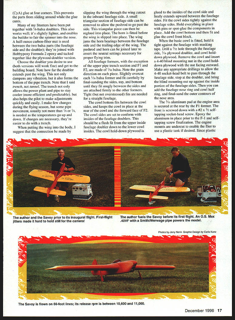
- Total line length: 66 feet (center of handle to center of model).
- Release RPM: 10,500–11,000. The engine may sound fast at idle on the ground but should settle after a couple of laps.
- Expected lap time: approximately 5.25–5.4 seconds.
- The 665‑square‑inch Savoy weighs about 61.5 ounces at launch.
PAMPA
- Having equipment is useless without knowledge. I highly suggest joining PAMPA to quicken your stunt learning curve.
- Stunt News (Tom Morris, Anniston, AL) is the definitive newsletter.
- Send PAMPA application requests to: PAMPA, 158 Flying Cloud Isle, Foster City, CA 94404.
- Requests for PAMPA products (includes a large stunt bibliography) can be sent to: Box 2026, Loomis, CA 95650‑2026.
SOURCES
- Randy Smith — Aero Products, 1880 Scenic Highway, Snellville, GA 30729
- Scott Smith — Aerosmith Model Aviation, RD #1 Box 290, Athens, NY 12015
- Byron Barker — C.F. Slattery, 407 Mount Tabor Rd., New Albany, IN 47150‑2206
- Doug Taffinder — Carolina‑Taffinder, 83455 Delhi Road, North Charleston, SC 29418
- Mike Pratt — Sig Manufacturing, 401‑7 South Front Street, Montezuma, IA 50171
If you have questions regarding the Savoy, please write to:
Allen Brickhaus Box 206 Golconda, IL 62938
Transcribed from original scans by AI. Minor OCR errors may remain.

