
Ex-cels 520
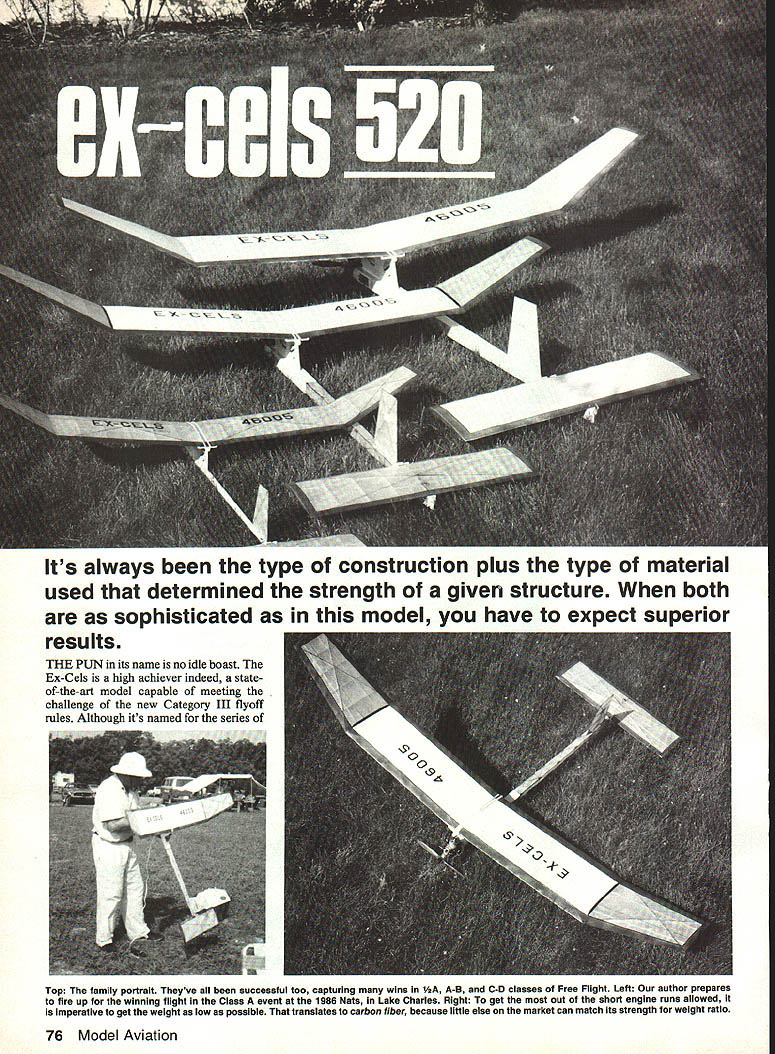
It's always been the type of construction plus the type of material used that determine the strength of a structure. When both are as sophisticated as in this model, you can expect superior results.
The pun in its name is no idle boast. The Ex-Cels is a high achiever — a state-of-the-art model capable of meeting the challenge of the new Category III flyoff rules.
I am indebted to Bob Violett, Bill Hunter, and several others whose ideas I have used and elaborated upon. Parts of my finished Ex-Cels resemble their versions; however, a good second look will show the model has undergone many evolutionary stages. Using unorthodox construction methods and materials, I experimented until I was satisfied I had made the necessary changes in design parameters to establish near-optimum performance.
Changes and results:
- Fin area was increased to control a wandering tendency on power.
- A variable-incidence tailplane (VIT) was added for optimum glide adjustment.
- The airfoil was changed, wing area increased about 9%, and wing taper improved.
- Overall drag was reduced while maintaining lift characteristics.
- Ultra-light construction and lighter tail feathers improved glide and allowed lengthening the tail moment while shortening the nose for added stability on power.
- The wing has 6 in. washout tips to reduce drag and is built without warps.
- Thrust settings: 0° downthrust and 1° left thrust. The model trims neutral and easy.
- Designed to increase acceleration and altitude from a four-second engine run, it has better chances of making a 2½-minute max.
Construction
Materials and general notes
- The X-frame adds tremendous rigidity; judicious use of carbon-fiber materials provides lightness.
- Carbon-fiber rod is easy to cut and handle and has no splinters. Use an electrician's combination stripper/cutter tool — put it in the 4-40 bolt-cutter hole and it shears the carbon fiber off cleanly. Carbon fiber sands and files readily.
- The .007-in. unidirectional laminate is very strong and dimensionally stable lengthwise but easily split across the grain. The easiest way to cut it is to snip to the desired width and then strip to the length needed. Avoid rubbing fingers along the edges to prevent splinters.
- Cyanoacrylate (CyA) glues work fine; epoxy, though heavier, is also good. Since CyA attracts and absorbs fuel-oil mix, do not use CyA around the firewall or fuel tank — use epoxy wherever a glue joint could be exposed to fuel.
Wing
Building the panels
- Use two straightedges over the plans as guides for the leading edge (LE) and trailing edge (TE). Make sure they are straight (I use 1/8 × 1½-in. aluminum strips). Drill small holes in the strips and tack them to the building board with small brads.
- Using pins on an angle, pin the LE and TE against the straightedges. Position the bottom spar and hold it with crossed pins or weights. Glue ribs in place, making sure dihedral and polyhedral ribs are at the correct angles.
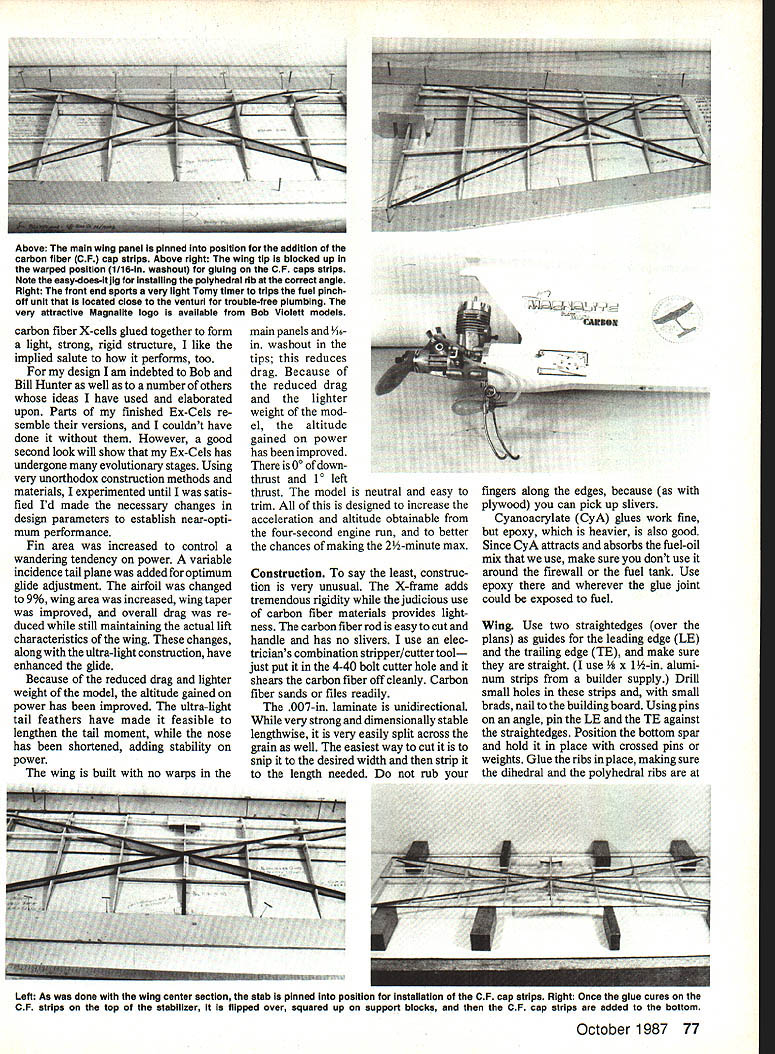
- Pin the center section in position and install carbon-fiber (CF) cap strips on the top. Once cured, flip the stabilizer over on squared-up support blocks and add CF cap strips to the bottom.
- Fit and glue webbing and carbon-fiber cap strips, placing the grain of the webbing parallel to the bottom. Leave the top webbing a little heavy and sand it flush with the ribs.
- Note: Using CF cap strips will leave them slightly above the rib surface. You can inset them flush if you wish, but it is a lot of work with little performance advantage.
Spars, cap strips, and fillets
- Carefully sand the webbing tops flush with the ribs (mark ribs with a soft charcoal pencil to tell when sandpaper reaches the ribs).
- Cut slots for the main spar and turbulator spars in the webbing and glue them in place.
- Keep CF cap strips centered and glue them on top of the webbing. Ensure the panel is perfectly flat or blocked to the desired warp — once cap strips are glued, panel structure cannot be changed.
- Turn the panel over, block up the LE and TE to the desired warp, and glue the bottom CF cap strips.
- Run a bead (fillet) of slow-set CyA along the webbing and cap strips and hit it with accelerator. This fillet is important — do it on both sides of the webbing for the wing (one side is OK for the stab).
Joining panels and dihedral/polyhedral braces
- Before joining panels, cut a slot in the dihedral and polyhedral ribs between the main spars for the plywood brace/webbing.
- Line up and block up a main panel and its matching tip panel. Fit the plywood brace/webbing between the main spars until it is a nice, easy fit — no binding. Spot-glue the brace/webbing to the main panel, then slide panels apart, apply slow-set CyA, slide back together, and allow to set in the lined-up, blocked position. Assemble the entire wing this way.
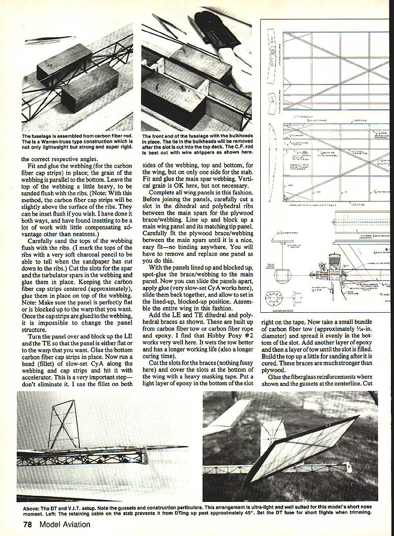
- Add the LE and TE dihedral and polyhedral braces as shown in the plans. Build these braces from carbon fiber tow or carbon fiber rope and epoxy (Hobby Poxy #2 works well — wets tow better and has longer working life).
- Cut slots and cover the bottom of the slots with heavy masking tape. Put a light layer of epoxy on the tape, add a small bundle of CF tow (approx. 1/16-in. diameter), spread evenly, add epoxy and additional tow until slot is filled. Build the top up a little for sanding after cure. These braces are stronger than plywood.
Reinforcements and finishing the wing
- Glue fiberglass reinforcements and gussets at the centerline where shown.
- Cut a slot into the top deck for tie-in from the fuselage top rods; tie-in in the bulkheads will be removed after the slot is cut.
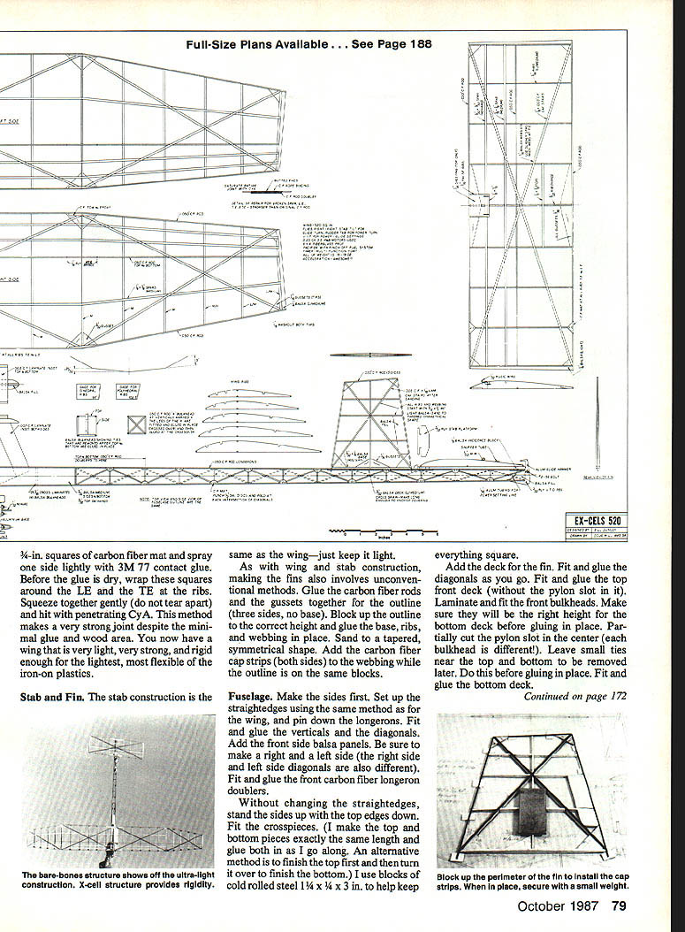
- Use 3/4-in. squares of carbon fiber mat sprayed lightly with 3M 77 contact glue. Before the glue dries, wrap these squares around the LE and TE at the ribs, squeeze gently (do not tear apart) and hit with penetrating CyA. This makes a very strong joint with minimal glue and wood area.
- The result is a wing that is very light, very strong, and rigid enough for the lightest, most flexible iron-on coverings.
Stab and Fin
- Stab construction follows the same method as the wing — keep it light.
- For fins: glue the carbon fiber rods and gussets together for the outline (three sides, no base). Block up the outline to the correct height and glue the base, ribs, and webbing in place. Sand to a tapered, symmetrical shape.
- Add carbon fiber cap strips (both sides) to the webbing while the outline is on the same blocks.
Fuselage
- Make the sides first. Set up straightedges as for the wing and pin down the longerons. Fit and glue the verticals and diagonals. Add front side balsa panels. Make right and left sides (diagonals differ).
- Fit and glue front carbon fiber longeron doublers.
- Without changing the straightedges, stand the sides up with the top edges down and fit the crosspieces. I make top and bottom pieces exactly the same length and glue both as I go. Use blocks of cold-rolled steel (1¼ × ¼ × 3 in.) to keep everything square.
- Add the deck for the fin. Fit and glue diagonals and the top front deck (leave the pylon slot unfinished).
- Laminate and fit the front bulkheads. Partially cut the pylon slot in each bulkhead (each is different). Leave thin areas near top and bottom to remove later; do this before gluing bulkheads in place. Fit and glue the bottom deck.
- Remove the fuselage from the board and fit and glue the carbon fiber X bulkheads — this requires patience.
- Punch out 1/32-in. dia. discs of carbon fiber mat, lightly spray one side with 3M 77, and before the glue dries fold them around joints where diagonals come together, then secure with penetrating CyA.
- Install the 1/2-ply timer plate, blind nuts, and timer. Install any dethermalizer (DT) hardware or auto-control setups at the proper phase of construction.
- Accurately cut the pylon slot in the top deck and remove ties from the bulkheads. The slot can be made long or lengthened to adjust the center-of-gravity (CG).
- Install the cheeks and carve to shape. Laminate, add blind nuts, and install the firewall.
- Install the stab platform, incidence block, and VTO (vertical takeoff) peg. Laminate and build the pylon and wing platform (I inset the carbon fiber strips in both the pylon and platform so they are flush — neater result). Fit the pylon to the fuselage, ensuring correct angle of attack.
Covering
- Any covering material may be used; the construction is light, strong, and rigid enough for even the lightest, most flexible iron-on plastics.
- I use Micafilm: clear, light-weight Micafilm on the rear fuselage, stab, fin, and wing tips; stronger, heavier white film on the main wing panels.
- Adhesives: use 3M 77 contact spray or Balsarite thinned to 60% glue / 40% thinner. Put two coats of thinned Balsarite (or one coat of 3M 77) on all surfaces that will contact the covering (except on CF cap strips).
- Cover the bottom first. Adhere the cover to the wing outline and shrink gently on low heat. Trim the outline and go over the glue contact line (inside CF rods) with penetrating CyA (no accelerator). Shrink completely on high heat, top and bottom.
- Check for and remove undesired warps. Run the iron (low heat) over every surface that contacts the covering (ribs, spars — not the CF cap strips). Work in small contact areas, rub firmly until cooled and set. Then go over entire surface on high heat to lock the covering taut.
- For visibility, outline the wing and stab with fluorescent orange paint. Clean the area to be painted with dope thinner for better adhesion. After spraying orange, apply a coat of Super Poxy over it.
Center-of-gravity (CG)
- Before finishing the front end, assemble all parts and hardware on the model — everything. To be safe, add about two grams of weight on the rear.
- Shift the wing forward or backward to the indicated CG — about 66%. At 69% the model becomes unstable. After disassembly, glue the pylon in this position.
- Finish the front end by your preferred method (lightweight fiberglass or tissue, nitrate dope, and Super Poxy). Add decals, AMA number, nameplate, etc., and assemble. Ensure the wing is mounted at exactly 90° and keyed on — misalignment can cause puzzling power patterns, especially on a hot model. Recheck the CG.
Flying
- Check all systems on the ground while the engine is running.
- I use a pincher fuel system (for pressure) with a pinch-off fuel cutout. The close proximity of the pinch-off to the venturi provides a quick, positive shutoff with no danger of leaning out and fouling plugs. As a result, plugs last longer and I can consistently run on higher nitro than with an old flood-off system.
- First flights:
- Start on 40% nitro with a 3–3½-second run and quick DT (4–5 seconds).
- Use a rudder tab and adjust the incidence block to control the power pattern. The ideal pattern is nearly vertical with a slight twist to the right.
- When satisfactory, gradually increase the engine run by about one second at a time and adjust.
- When the model can hold the power pattern for seven seconds (or longer), test and adjust the variable-incidence tail (VIT) for the glide. Use stab tilt for the glide circle. A seven-second engine run and a 15–20 second glide to DT should keep the model out of trouble.
- After glide adjustment, increase fuel to 50% nitro and start over on the power pattern (3–3½-second runs), repeating adjustments each time nitro percent is increased.
- Handle the model with TLC — you now have a model that is super-light, super-strong, and very competitive. See you at the flyoffs!
Sources for carbon fiber material
- Bob Violett — 1373 Citrus Rd., Winter Springs, FL 32708 (0.050 dia. rod, mat, tape, and laminates)
- Twin-K, Inc. — P.O. Box 31228, Indianapolis, IN 46231 (0.070 dia. rod, mat, and laminates)
- Jim Bradley — 1337 Pine Sap Ct., Orlando, FL 32817 (0.060 dia. rod, mat, and laminates)
- Aerospace Composite Products — P.O. Box 16621, Irvine, CA 92714 (0.050, 0.060, 0.070 dia. rods, mat, rope, and laminates)
Transcribed from original scans by AI. Minor OCR errors may remain.

