
Excitation
If you have an interest in any form of competition, this story is must reading. The author's odyssey through three Nats and two close-but-no-champagne endings culminating in a heartbreaker is striking, whether or not you're into CL Precision Aerobatics. Plans are included for construction of this very special airplane. • Ted Fancher
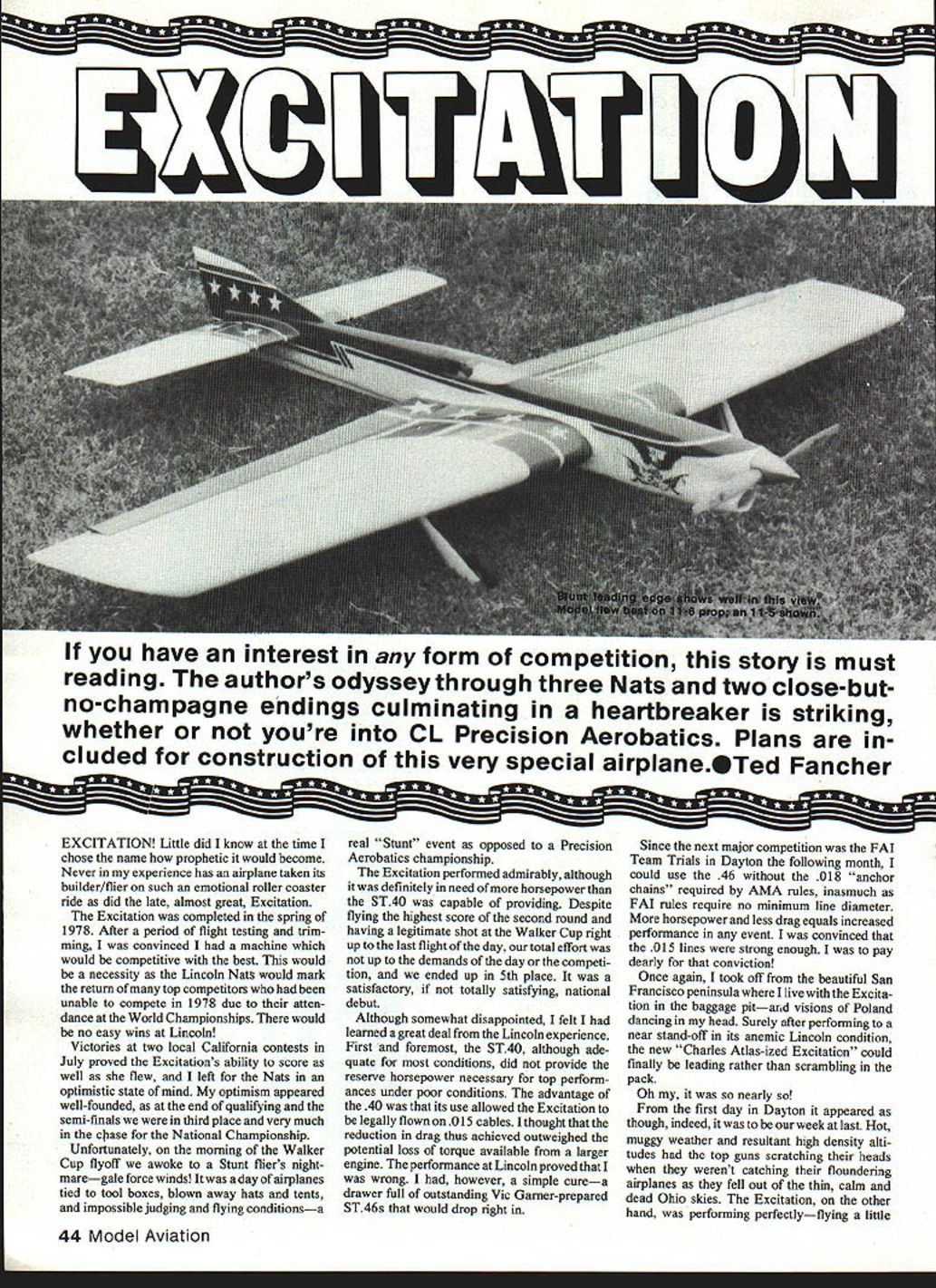
Excitation! Little did I know at the time I chose the name how prophetic it would become. Never in my experience has an airplane taken its builder/flier on such an emotional roller-coaster ride as did the late, almost-great Excitation.
The Excitation was practically completed in the spring of 1978. After a period of flight testing and trimming I was convinced the machine would be competitive. Returning to top competition at the Lincoln Nats, after the absence of several top flyers the previous year, would be no easy task. Victories at two local California contests in July proved Excitation's ability to score well, and I left for the Nats optimistic.
At Lincoln, qualifying and the semi-finals found us in third place and very much in the chase for the National Championship. Unfortunately, the morning of the Walker Cup flyoff brought gale-force winds—every stunt flier's nightmare. It was a day of airplanes tied to tool boxes, blown-away hats and tents, and impossible judging and flying conditions. The Excitation performed admirably, but the ST.40 engine proved to be underpowered for the poor conditions. Although we flew the highest score of the second round and had a legitimate shot at the Walker Cup right up to the last flight, we finished in 5th place—a satisfactory, if not totally satisfying, national debut.
What I learned at Lincoln was clear: the ST.40, while adequate in many conditions, lacked the reserve horsepower needed to perform at the top under adverse conditions. The advantage of the .40 was that it allowed use of .015 cables, reducing drag, and I had believed that reduction outweighed the extra torque of a larger engine. Lincoln proved me wrong. My cure was simple: a drawer full of outstanding Vic Garner–prepared ST.46s that would drop right in.
Since the next major competition was the FAI Team Trials in Dayton the following month, I could use the .46 (FAI rules require no minimum line diameter). More horsepower and less drag meant increased performance. I was convinced the .015 lines were strong enough—an assumption I would later regret.
From the San Francisco peninsula I flew to Dayton with Excitation in the baggage pit and visions of Poland dancing in my head. On the first day at Dayton things looked very promising. Hot, muggy weather and high density altitude had many top competitors struggling, but Excitation responded superbly to the extra power—flying faster and more positively. At the end of qualifying we led by a sizable margin, having had the highest score in each round. I was on Cloud Nine.
For two rounds the next day things continued going my way. Going into the third and final round we were in a solid second place with a shot at first. After a practice flight, my mentor Bill Fitzgerald—hard to please—told me, "You're finally starting to get the idea." Pumped, I moved to the pull-test area for my last flight. "OK, Ted, you pull, and I'll release." No sweat—I'd done this thousands of times. A snap and a jerk...the up line broke.
I had no spare lines. The controls were jammed full down. An internal part had apparently broken. Bob Whitely and Bart Klapinski brought a knife and surgery began. Bob Hunt warned I had to fly after the next flight or lose my turn. We managed to free the bellcrank that had swung past center and jammed. The flaps and elevators were both down about 15°, later found to be caused by a control horn twisted some 20° and a broken solder joint between the arms and the flap control horn. With hurried repairs and fingers crossed, I flew. The handle setup wasn't right; the flight was rough and marginal. After all the scores were in, we had not made the team and had fallen to 6th place. I was an emotional wreck and came close to quitting competition.
More complete examination at home uncovered the control trauma described above. Surgery and retrimming were performed, and the Excitation—this "Devil Lady"—appeared ready for another assault on the Walker Cup.
Come 1980, we made one last pilgrimage to the Wilmington Nats. Early in the week I was not well prepared and was sleep-deprived from travel. After practice, qualifying, and an almost-disastrous first semi-final round, I finally had my health, my airplane, and my act together. For the fourth year in a row I was in 3rd place entering the Walker Cup flyoff and again felt optimistic.
The morning of finals was a little cloudy and blustery but manageable. At dawn, with Bill Fitzgerald helping, the Garner ST.46 barked to life for the first of planned warm-up flights. The Excitation came off a bit rich in the cool air and we ran a slow pattern to burn fuel and settle my nerves. After completing the pattern I habitually fly three outside triangles to clear the lines for landing. On the last inverted corner of the triangles, the Excitation gave a jerk through the lines; the controls failed. A quarter lap later she hit the concrete, scattering debris about Bill Fitzgerald's feet—perhaps a final rude gesture at his endless criticism of her.
The final failure was traced to a broken pin in a heavy-duty 4-40 Kwik-Link. That pin had probably been weakened by the extreme loads placed on it during the line failure ten months earlier. The link should have been replaced. It wasn't, and as a result one of the outstanding stunt ships of the last two years became only a memory.
The design, however, proved to be a high-level performer and is a worthy project for anyone interested in serious stunt activity. A second Excitation—probably to be renamed for superstitious reasons—was nearing completion in my shop as this was written. This time, preparation and execution will be worthy of the Excitation's aerobatic potential.
Construction
General
Excitation was designed in early 1978 and incorporates many design characteristics tested in my Imitation (see MA September and October 1979). Specifically, these designs utilize:
- A higher-than-normal aspect-ratio wing with blunt leading edges and narrow chord
- Nearly full-span flaps
- A long tail moment
- A moderate-size, low-aspect-ratio horizontal stab and elevator
- A refined control system with longer control horns and a larger bellcrank moving smaller-than-customary control surfaces
Rather than reiterate the design logic in full, refer to the Imitation article for general hypotheses; they remain unchanged.
Excitation is generally conventional in construction. The most unusual feature is the very thick built-up stabilizer and elevator; I deal with that in detail below.
Wings and foam cores
The wing (and, if desired, the stab and elevator) are available from J and K Custom Foam Wings, 10261 Janice Lynn, Cypress, CA 90630. I strongly urge builders—especially those new to competitive aerobatics—to take advantage of John Poynter's expertise. Foam wings from skilled artisans are straight, light, and for what you get, inexpensive.
The J and K wings are offered in varying degrees of completion:
- Master series: sheeted with leading and trailing edges installed and shaped, lite-ply spar and gear supports in place (ultimate ready-to-finish option)
- Master series without gear supports for a slightly lower price (supports are cheap insurance; they are extremely secure)
Wings come with complete assembly instructions showing bellcrank installation and the method of joining panels (butt joint reinforced all around with lightweight glass cloth and HobbyPoxy Formula II).
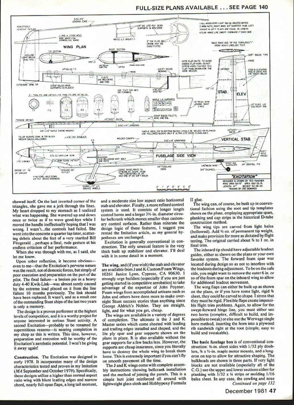
Of course, the wing can be built conventionally using the root and tip templates on the plans, with appropriate spars, planking, and cap strips in the D-tube construction tradition.
Wing tips and leadouts
Wing tips are carved from light balsa (hollowed). Add approximately 1/2 oz permanent tip weight and provide the ability to add more during flight testing; the original carried about 3/4 to 1 oz in final trim.
The inboard tip should have adjustable leadout guides, either as shown on the plans or your own preferred system. The forward foam spar was located during design so as not to interfere with leadouts during adjustment. To be safe, remove the outer 6 in. or so of the foam spar on the inboard wing to allow additional leadout movement.
Flaps
Flaps can be built up as shown on the plans or, if you have light, rigid 3/16-in. sheet, they may be carved to shape. They must be rigid—flexible flaps create impossible trim problems. Because the hinge line is swept forward, you must either:
- Use two horns (complex, difficult to build, and hard to tweak), or
- Use the Wierwage single-horn method: insert the horn into a plywood rib sandwich right at the root (simple, easy to build and tweakable).
Ensure the flap horn arms enter the flap right at the root with a very strong joint—a plywood sandwich epoxied directly to the flap root is recommended.
Fuselage
The basic fuselage box is conventional: 1/8-in. sheet sides with 1/32-in. ply doublers, 1/8 x 1/4-in. maple motor mounts, and a top longeron for shaping. Bulkheads are shown in three parts. If very light blocks are unavailable (especially at the CG), use the upper and lower sections for planking with 3/32 x 3/4 strips or mold 1/16-in. balsa sheet.
My procedure: build the fuselage box, tack-glue the cowl, turtledeck, top, and bottom blocks in place and shape the whole assembly to near completion. Pop off the blocks, pin the fuselage box upside down to a large flat building board, cut out the belly cradle, and carefully align and install the wing. Use a slow-drying glue for a strong joint. Measure, remeasure, and measure again—alignment is critical to performance.
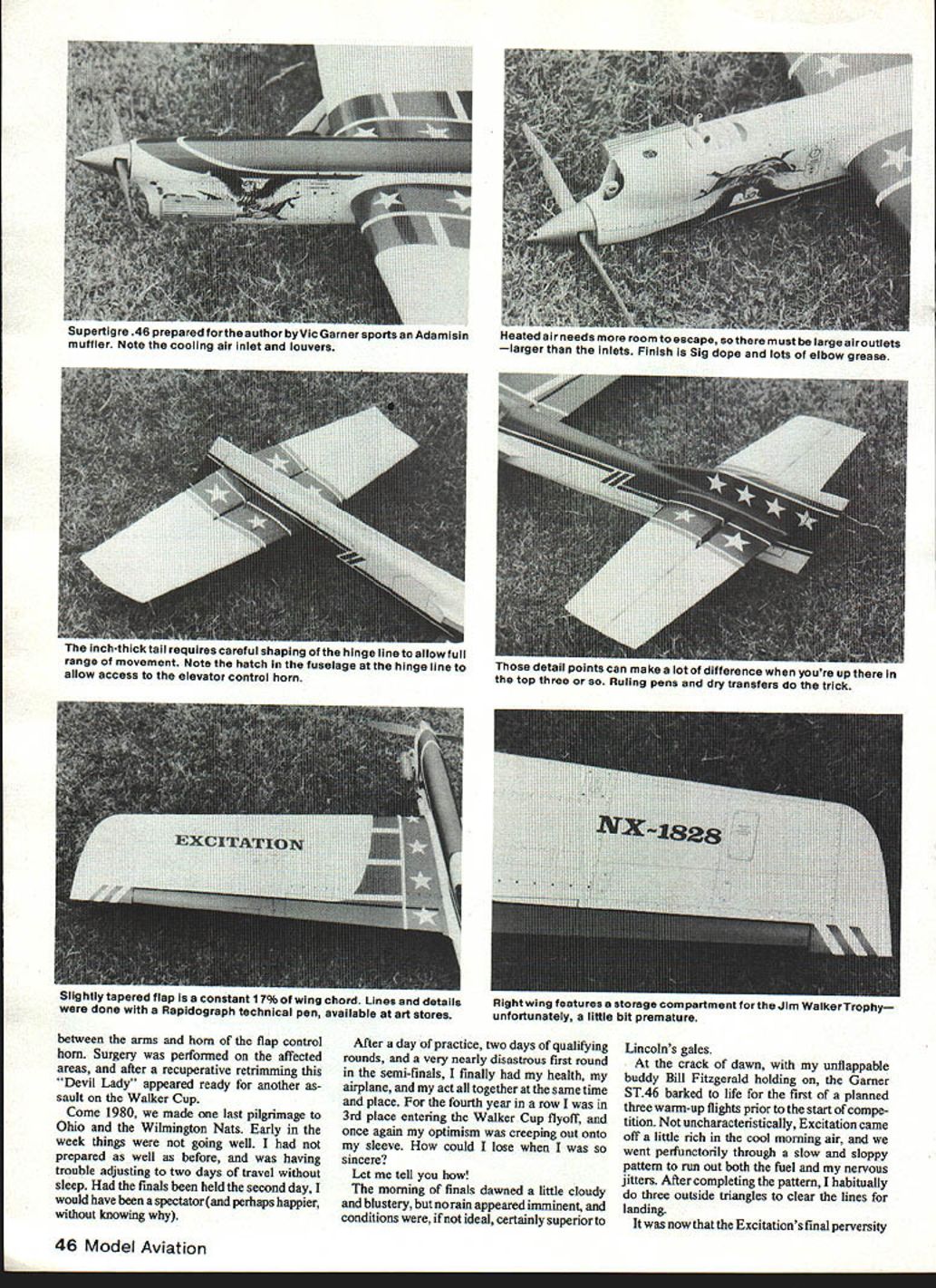
Tail and control surfaces
The tail is built-up like a small wing. Make 1/32-in. plywood templates of the root and tip ribs. Sandwich the appropriate number of 1/16-in. rib blanks between the templates and sand to shape. Glue the ribs to the spars, making sure they are 90° to the spar and properly aligned. Add scrap balsa supports for hinge areas.
Cut skins from very light 1/16-in. balsa sheet. Two stab and four elevator skins are necessary. Glue the stab skins to the spars only. When dry, apply Titebond to all ribs and pin skins securely to ensure uniform adhesion. When dry, sand flush and glue the 1/8-in. leading edge in place. Cut hinge slots and install hinges.
For elevators, cut hinge slots to match the stab, then apply sheeting to both sides at once with Titebond and shape with a sanding board. If built with good wood and sound construction, you should have a 140 sq. in. stab and elevator weighing about 1 to 1-1/4 oz.
A key trick: do not permanently attach the tail blocks until all controls are installed and final pushrod adjustments completed. Attaching top and bottom blocks too early often twists the fuselage and ruins alignment. Install all controls and leave a little fore-and-aft movement for the stab. After permanently attaching the turtledeck and bottom block, glue the tail in place with the fuselage rigid and pinned in neutral. When dry, check for any twist and correct with shims before adding a glue fillet.
Cut and shape the rudder and vertical stabilizer from 1/4-in. balsa. Hinge the rudder with soft wire so it can be adjusted. Glue in the conventional location at the top rear of the fuselage. Cut the ventral fin from 1/4-in. firm balsa. Install the tail-wheel wire, reinforcing with medium-weight glass cloth and HobbyPoxy Formula II.
Canopy and cockpit
The original canopy was molded from .040-in. butyrate plastic in a vacuum box, but many commercial canopies are suitable. The back of an RC teardrop canopy often fits this style well.
Cockpit detail level is your choice. Trends move toward basics: a pilot head, a few instruments, and a darkly tinted canopy or a painted-on cockpit carved from balsa blocks. Some creative mockups (a painted interior with a small paper label “Cockpit Detail”) make a point—imagination is welcome.
Finish
Make the finish neat and light. Fillets and paint add weight—paint especially is heavy. Until fillets are as good as the masters, keep finish simple and light.
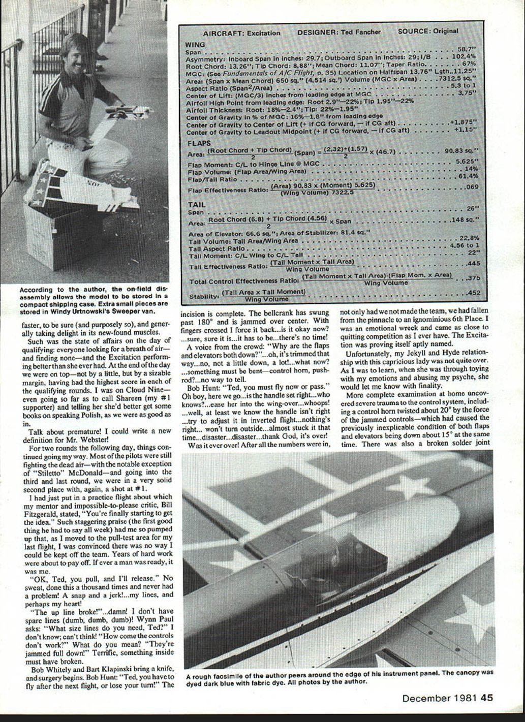
The design
I have included my standard pre-drafting numbers sheet detailing Excitation's design parameters. A comparison with the Imitation numbers shows the two are nearly identical aerodynamically. The major difference is a more highly tapered wing (primarily for appearance), which resulted in a swept-forward flap hinge line. Achieving a 67% taper ratio with a straight hinge line would have required a highly swept leading edge and a fuselage forward of the leading edge that was too short to fit a tank.
The swept-forward flaps will work smoothly with a single horn if carefully constructed per the drawings. Make the flap root horn a plywood sandwich and epoxy it to the flap root for adequate strength.
Final weight should be in the low 50-oz. range for best performance. Excitation, at about 650 sq. in. area, is small by current standards. Higher weights will still fly but power loading becomes marginal, particularly in vertical maneuvers.
Trimming and controls
Control system
The longer-arm control system provides adequate mechanical advantage over control-surface air loads even in severe circumstances. The setup shown:
- 3/4-in. diameter circular bellcrank
- 9-in. pushrod arm on the bellcrank
- 7.5-in. control horn arms
This results in a sensitive system with a conventional 4-in. handle (e.g., a Hot Rock). I encourage the use of a Baron-style adjustable handle to tailor control sensitivity to your taste. Do not add nose weight simply to desensitize control feel—doing so trims the airplane below its aerobatic potential.
Center of gravity (CG)
Optimum CG location is found through flight testing. Move the CG aft in quarter-inch increments and observe flight behavior. At a certain point the ship will go hard and flat around a corner with no tendency to hunt after neutralizing controls. How far aft you can go depends on the K or stability factor; designs with a long tail moment and/or large tail area will accept further-aft CGs than designs with a small or short tail.
When the hard flat corner is achieved the ship may be too sensitive for your taste—do not add nose weight to reduce sensitivity. The next CG indication is how the ship glides when the engine quits: if the CG is too far aft the ship will go light on the lines and nose up slightly, making smooth approach and landing difficult. Add only enough nose weight to restore positive control. With a reasonably sized tail, you will find both goals (firm corners and safe glide) within a fraction of an inch of the same CG location.
Fine-tuning
Once the CG is set, adjust handle line spacing to fine-tune sensitivity. When properly trimmed, you will have an airplane comfortable for you to fly yet aerodynamically trimmed to its maximum potential, with reserve available by opening up line spacing when needed.
Lessons learned and conclusion
When I first conceived of Excitation, I never imagined the emotional roller-coaster she would deliver. The airplane's final perversity was not demonic but a consequence of pilot lapses: failing to replace a damaged Kwik-Link after a previous failure cost the airplane and a championship opportunity.
Despite the personal disappointments, Excitation is a proven performer at the highest levels of competition. It is more than another Nobler with new cosmetics; it is a refined, better mousetrap designed to fit one man's demands but adaptable to various flying styles. A properly trimmed Excitation can be adjusted to suit any precision aerobatics flier. If you are interested in serious stunt activity, it is a worthy project. How about you?
Transcribed from original scans by AI. Minor OCR errors may remain.

