
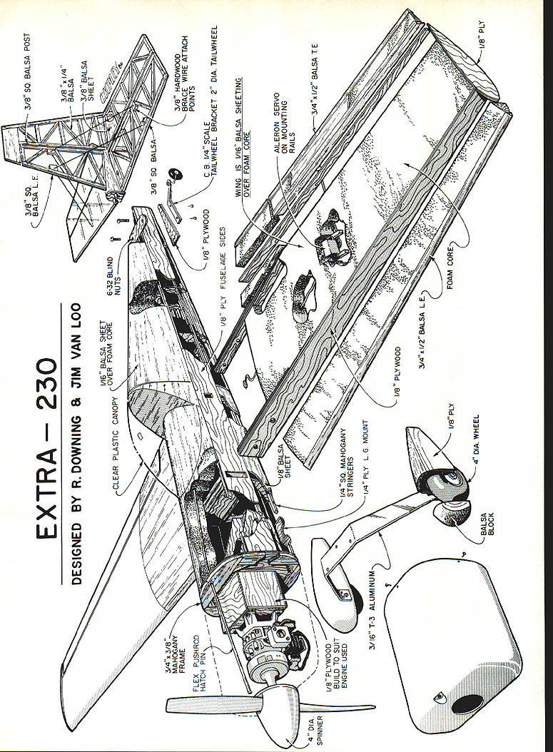
EXTRA 230
Design by Richard Downing and Jim Van Loo
Text by Jim Van Loo
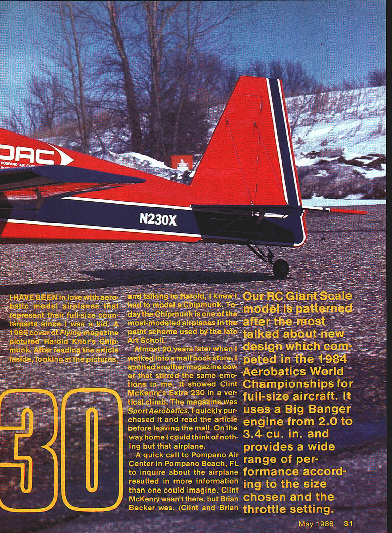
I have been in love with aerobatic model airplanes that represent their full-size counterparts since I was a kid. A 1966 cover of Flying magazine pictured Harold Krier's Chipmunk. After reading the article inside, looking at the pictures, and talking to Harold, I knew I had to model a Chipmunk. Today the Chipmunk is one of the most-modeled airplanes in the paint scheme used by the late Art Scholl.
Almost 20 years later, when I walked into a mall bookstore, I spotted another magazine cover that stirred the same emotions in me. It showed Clint McKenry's Extra 230 in a vertical climb. The magazine was Sport Aerobatics. I quickly purchased it and read the article before leaving the mall. On the way home I could think of nothing but that airplane.
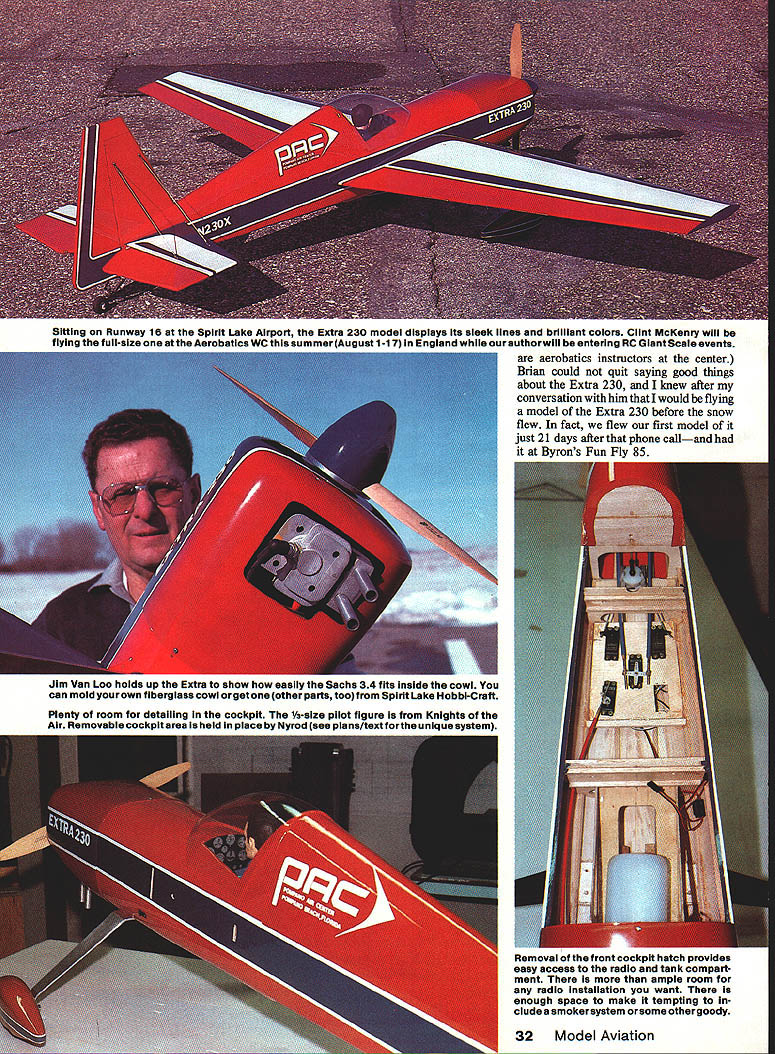
A quick call to Pompano Air Center in Pompano Beach, FL, to inquire about the airplane resulted in more information than one could imagine. Clint McKenry wasn't there, but Brian Becker was. (Clint and Brian were entering RC Giant Scale events. Brian, an aerobatics instructor, couldn't quit saying good things about the Extra 230.) I knew after talking to him I would have to fly a model Extra 230. In fact, I flew my first model just 21 days after the phone call at Byron's Fun-Fly '85.
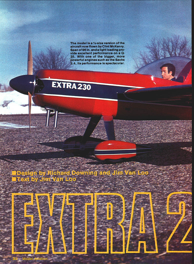
Our RC Giant Scale model is patterned after the most talked-about new design which competed in the 1984 Aerobatics World Championships for full-size aircraft. It uses a Big Banger engine from 2.0 to 3.4 cu. in. and provides a wide range of performance according to the size chosen and the throttle setting.
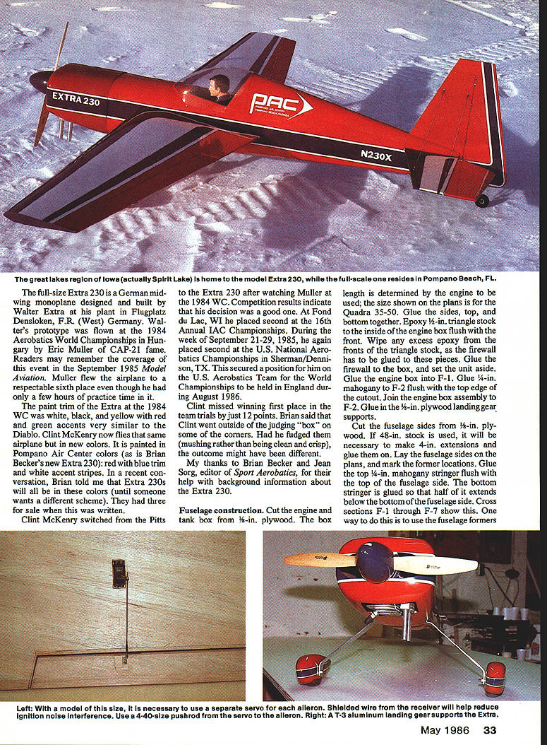
Spirit Lake (in the Great Lakes region of Iowa) is home to the model; the full-size Extra 230 resides in Pompano Beach, FL. The full-size Extra 230 is a German midwing monoplane designed and built by Walter Extra at the Extra plant, Flugplatz Denzlingen, FRG, West Germany. Walter's prototype was flown in the 1984 Aerobatics World Championships in Hungary by Eric Müller (CAP-21 fame). Müller flew the airplane to a respectable sixth place, though he had only a few hours practice time.
The Extra at the 1984 World Championships was white with black, yellow, red, and green accents—very similar to Diablo. Clint McKenry now flies the same airplane, newly painted in Pompano Air Center colors. Brian Becker's new Extra 230 is red with blue trim and white accent stripes. Extras will generally retain those colors until someone requests a different scheme.
Clint McKenry switched to the Extra 230 after watching Müller's 1984 performance. Competition results indicate the decision was a good one. At Fond du Lac, WI, Clint placed second in the 16th Annual IAC Championships. During the week of September 21–29, 1985, he again placed second in the U.S. National Aerobatics Championships at Sherman/Dennison, TX, securing a position on the U.S. Aerobatics Team for the World Championships held in England during August 1986. Clint missed winning first place in the team trials by just 12 points; Brian said Clint went outside the judging box—some corners were mushed rather than clean and crisp—and the outcome might have been different.
Thanks to Brian Becker and Jean Sorg, editor of Sport Aerobatics, for help and background information about the Extra 230.
Fuselage construction
- Cut the engine/tank box from 1/8-in. plywood. The box length is determined by the engine to be used; the size shown on the plans is for the Quadra .35–.50. Glue the sides, top, and bottom together.
- Epoxy 1/2-in. triangle stock to the inside of the engine box flush with the front. Wipe any excess epoxy from the fronts of the triangle stock, as the firewall has to be glued to these pieces. Glue the firewall to the box, and set the unit aside.
- Glue the engine box into F-1. Glue 1/4-in. mahogany to F-2 flush with the top edge of the cutout. Join the engine box assembly to F-2. Glue in 3/16-in. plywood landing-gear supports.
Cut the fuselage sides from 3/16-in. plywood. If 48-in. stock is used, it may be necessary to make extensions and glue them on. Lay the fuselage sides on the plans and mark former locations. Glue the top 1/4-in. mahogany stringer flush with the top of the fuselage side. The bottom stringer is glued so that half of it extends below the bottom of the fuselage side (see cross sections F-1 through F-7). One way to do this is to use the fuselage formers.
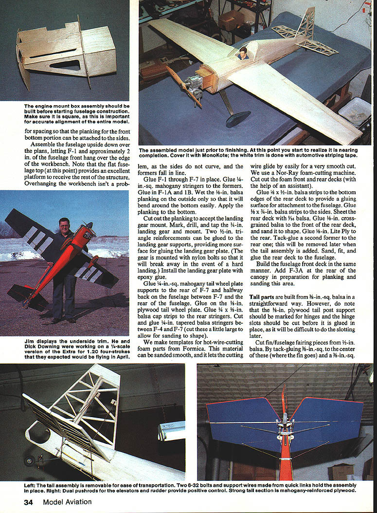
Assemble the fuselage upside down over the plans, letting F-1 and approximately 2 in. of the fuselage front hang over the edge of the workbench. The flat fuselage top provides an excellent platform to receive the rest of the structure; the overhang is not a problem since the sides curve and the formers fall into line. Glue F-1 through F-7 in place. Glue 1/8-in.-sq. mahogany stringers to the formers. Glue F-1A and F-1B.
Wet-in balsa planking on the outside will bend around the bottom easily. Apply 1/16-in. balsa planking to the outside and plank the bottom. Cut out the planking to accept the landing-gear mount. Mark, drill, and tap the 6-32-in. landing-gear mount (or follow the plan-specified size). Two triangle reinforcements (see plans for exact size) can be glued to the fuselage bottom for added strength.
Glue 1/4-in.-sq. mahogany tail-wheel plate supports to the rear of F-7 and halfway back on the fuselage between F-7 and the rear of the fuselage. Glue on the 1/8-in. plywood tail-wheel plate. Glue 1/4 x 1/8-in. balsa cap strips to the rear stringers. Cut and glue 1/4-in. tapered balsa stringers between F-4 and F-7 (cut these slightly oversize to allow for sanding to shape).
We make templates for hot-wire-cutting foam parts from Formica; this material can be sanded smooth and lets the cutting wire glide for a very smooth cut. A Nor-Ray foam-cutting machine is used to cut the foam front and rear decks (with the help of an assistant).
- Glue 1/8 x 1/2-in. balsa strips to the bottom edges of the rear deck to provide a gluing surface for attachment to the fuselage. Glue 1/8 x 3/8-in. balsa strips to the sides.
- Sheet the rear deck with 1/16-in. balsa. Glue 1/8-in. cross-grained balsa to the front of the rear deck, and sand it to shape. Glue 1/8-in. Lite Ply to the rear.
- Tack-glue a second former to the rear; this will be removed later when the tail assembly is added. Sand, fit, and glue the rear deck to the fuselage.
Build the fuselage front deck in the same manner. Add F-3A at the rear of the canopy in preparation for planking and sanding this area.
Tail parts are built from 3/8-in.-sq. balsa in a straightforward way. Note that the 1/8-in. plywood tail-post support should be marked for hinges and the hinge slots cut before it is glued in place, as it will be difficult to do the slotting later.
On models of this size it is necessary to use a separate servo for each aileron. Wiring the receiver properly will help reduce ignition-noise interference. Use 4-40-size pushrods for the ailerons. Use T-3 aluminum landing-gear supports (or equivalents specified on the plans).
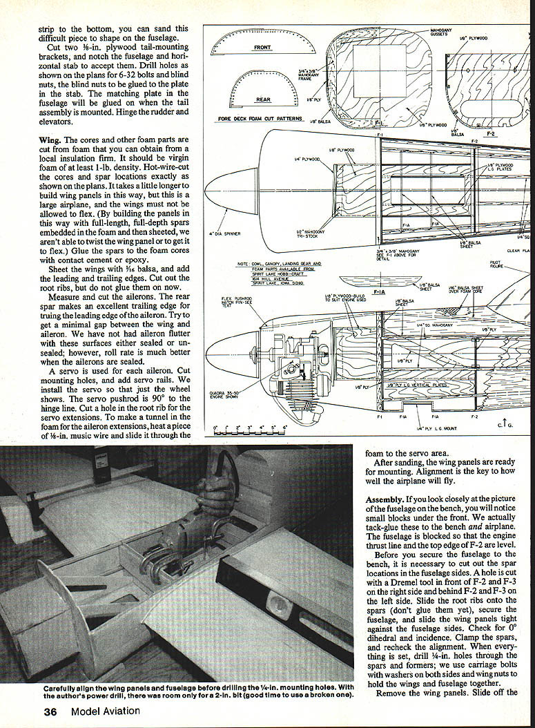
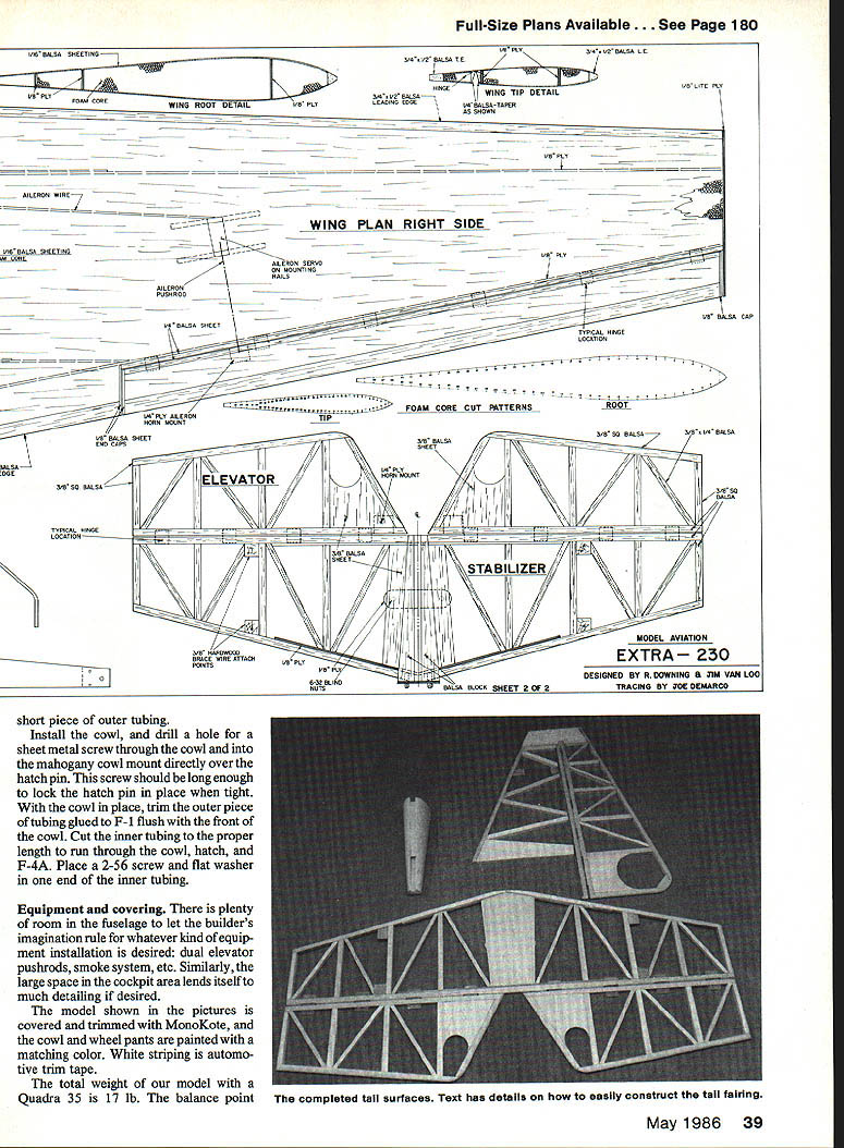
Wing
- The cores and other foam parts are hot-wire cut from virgin foam of at least 1-lb. density; obtain from a local insulation firm. Hot-wire-cut the cores and spar locations exactly as shown on the plans.
- Glue the spars to the foam cores with contact cement or epoxy. By embedding full-length, full-depth spars in the foam and then sheeting, the wing panels are stiff and will not twist or flex.
- Sheet the wings with 1/8-in. balsa, and add leading and trailing edges. Cut out the root ribs but do not glue them on yet.
- Measure and cut the ailerons. The rear spar makes an excellent trailing edge for truing the leading edge of the aileron. Try to get a minimal gap between the wing and aileron. No aileron flutter has been observed with these surfaces either sealed or unsealed; however, roll rate is better when the ailerons are sealed.
- A servo is used for each aileron. Cut mounting holes and add servo rails; install the servo so that just the wheel shows. The servo pushrod is 90° to the hinge line. Cut a hole in the root rib for servo extensions.
- To make a tunnel in the foam for the aileron extensions, heat a piece of 1/8-in. music wire and slide it through the foam to the servo area.
After sanding, the wing panels are ready for mounting. Alignment is the key to how well the airplane will fly.
Assembly
- Block the fuselage on the bench so the engine thrust line and the top edge of F-2 are level. Small blocks under the front can be tack-glued to the bench and a spar to stabilize the fuselage.
- Before securing the fuselage to the bench, cut out the spar locations in the fuselage sides. A hole is cut with a Dremel tool in front of F-2 and F-3 on the right side and behind F-2 and F-3 on the left side.
- Slide the root ribs onto the spars (don't glue them yet), secure the fuselage, and slide the wing panels tight against the fuselage sides. Check for 0° dihedral and incidence. Clamp the spars and recheck alignment.
- When everything is set, drill 1/4-in. holes through the spars and formers; carriage bolts with washers on both sides and wing nuts are used to hold the wings and fuselage together.
- Coat the ends of the panels with epoxy, return the root ribs to the panels, and put the spars back in the fuselage. Put a piece of wax paper between the spars and formers, and install the carriage bolts to secure the wings solidly. Recheck the alignment.
- Fold the wax paper over the top of the spar, and glue 1/4-in. mahogany alignment guides in place. Any gap between the wing panels and root ribs can be filled with Model Magic filler after the epoxy dries.
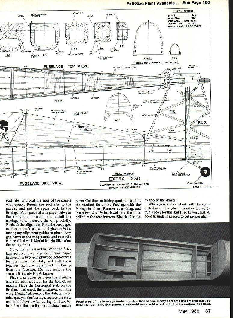
Tail assembly
- Cut two 1/8-in. plywood tail-mounting brackets, and notch the fuselage and horizontal stab to accept them. Drill holes as shown on the plans for 6-32 bolts and blind nuts; the blind nuts are to be glued to the plate in the stab. The matching plate in the fuselage will be glued on when the tail assembly is mounted. Hinge the rudder and elevators.
- With the fuselage secure, place a piece of wax paper between the two 3/8-in. plywood hold-downs for the horizontal stab, and bolt them together. Remove the shaped tail fairing from the fuselage but do not remove the second 1/8-in. ply F-7A former.
- Place wax paper between the fuselage and stab with a cutout for the hold-down mount. Place the horizontal stab on the fuselage and check alignment with the wing. If satisfied, remove the stab, apply 5-min. epoxy to the fuselage, replace the stab, and hold it level. After curing, drill two 1/4-in. holes in the rear formers as shown on the plans.
- Cut the rear fairing apart and trial-fit the vertical fin to the fuselage with the fairings in place. Remove everything and insert two 3/16 x 1-1/2-in. dowels into the holes drilled in the rear formers. Slot the fairings to accept the dowels.
- When satisfied with the completed assembly, glue it together. 5-min. epoxy can be used but work quickly. A good triangle is needed to get proper alignment.
- Glue 1/4 x 3/8-in. strips to the rear of the fuselage for tail support alignment.
- Rear tail support wires are made from quick links and solder links. These supports are necessary; without them the horizontal stab would not be strong enough during maneuvers. Remove the supports prior to covering. Install the tail wheel (a C.B. Associates 1/4-scale assembly was used on the prototype).
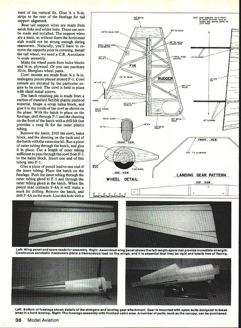
Wheel pants, cowl, and hatch
- Make the wheel pants from balsa blocks and 1/8-in. plywood, or purchase 10-in. fiberglass wheel pants.
- Cowl mounts are made from 3/4 x 3/8-in. mahogany pieces placed around F-1. Cowl cutouts are dictated by the particular engine used. The cowl is held in place with sheet metal screws.
- The hatch retaining pin is made from a section of standard flexible plastic pushrod outer tubing. Shape a scrap balsa block and glue it to the inside of the cowl as shown on the plans.
- With the hatch in place on the fuselage, drill through F-1 and the sheeting on the front of the hatch with a drill bit that provides a snug fit for the outer plastic tubing. Remove the hatch and drill the cowl, balsa block, and the sheeting on the back end of the hatch with the same size bit. Run a piece of outer tubing through the hatch and glue it in place. Cut a length of outer tubing sufficient to pass through the cowl from F-1 to the balsa block. Insert one end of this tubing into F-1.
- Glue a piece of pencil lead to one end of the inner tubing. Place the hatch on the fuselage. Push the inner tubing through the outer tubing glued to F-1 and through the outer tubing glued in the hatch. When the pencil lead contacts F-4A it will make a mark for drilling. Remove the hatch and drill F-4A on the mark. Line this hole with a short length of tubing for the retaining pin.
- Install the cowl and drill a hole for a sheet metal screw through the cowl and into the mahogany cowl mount directly over the hatch pin. This screw should be long enough to lock the hatch pin in place when tight. With the cowl in place, trim the outer piece of tubing glued to F-1 flush with the front of the cowl. Cut the inner tubing to the proper length to run through the cowl, hatch, and F-4A. Place a 2-56 screw and flat washer in one end of the inner tubing.
If using metal gear supports, mark, drill, and tap the fuselage floor for the mounting screws. Use the T-3 aluminum landing gear supports shown on the plans, or fabricate suitable replacements. Install the landing gear and check alignment.
Spacing and planking (additional notes)
- The front bottom portion of the planking can be attached to the fuselage sides first. Assemble the fuselage upside down over the plans, letting F-1 and the fuselage front hang over the edge of the workbench.
- Glue F-1 through F-7 in place. Glue 1/8-in.-sq. mahogany stringers to the formers. Glue F-1A and F-1B. Wet 1/8-in. balsa planking will bend around the bottom easily; apply the bottom planking.
- Cut out the planking to accept the landing gear mount. Mark, drill, and tap the inboard landing gear mount. Two triangle reinforcements (see plans) can be glued in as shown.
Equipment and covering
There is plenty of room in the fuselage to let the builder's imagination rule for equipment installation: dual elevator pushrods, smoke system, etc. The large space in the cockpit area lends itself to much detailing if desired.
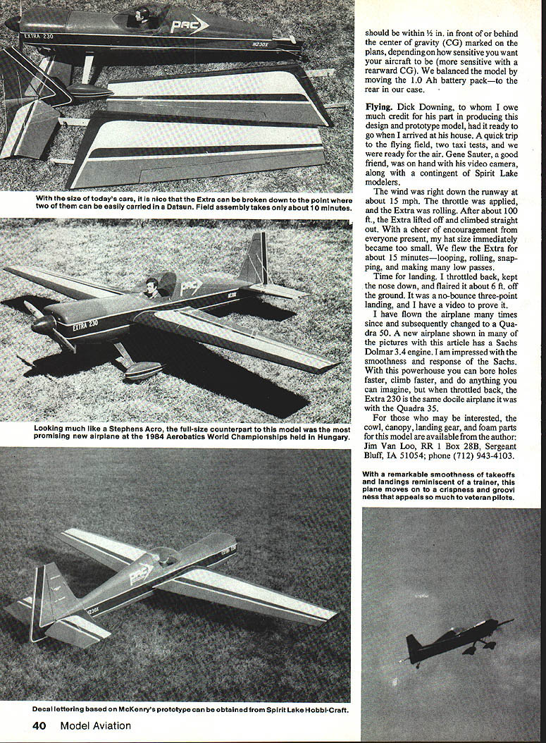
The model shown in the pictures is covered and trimmed with MonoKote, and the cowl and wheel pants are painted to match. White striping is automotive trim tape.
The total weight of our model with a Quadra .35 is 17 lb. The balance point should be within 1/2 in. in front of or behind the center of gravity (CG) marked on the plans, depending on how sensitive you want your aircraft to be (more sensitive with a rearward CG). We balanced the model by moving the 1.0 Ah battery pack—to the rear in our case.
Flying
Dick Downing, to whom I owe much credit for his part in producing this design and prototype model, had it ready to go when I arrived at his house. A quick trip to the flying field, two taxi tests, and we were ready for the air. Gene Sauter, a good friend, was on hand with his video camera, along with a contingent of Spirit Lake modelers.
The wind was right down the runway at about 15 mph. The throttle was applied, and the Extra was rolling. After about 100 ft., the Extra lifted off and climbed straight out. With a cheer of encouragement from everyone present, my hat size immediately became too small. We flew the Extra for about 15 minutes—looping, rolling, snapping, and making many low passes.
Time for landing: I throttled back, kept the nose down, and flared about 6 ft. off the ground. It was a no-bounce three-point landing, and I have a video to prove it.
I have flown the airplane many times since and subsequently changed to a Quadra .50. A new airplane shown in many of the pictures with this article has a Sachs Dolmar 3.4 engine. I am impressed with the smoothness and response of the Sachs. With this power house you can bore holes faster, climb faster, and do anything you can imagine, but when throttled back, the Extra 230 is the same docile airplane it was with the Quadra .35.
For those who may be interested, the cowl, canopy, landing gear, and foam parts for this model are available from the author:
- Jim Van Loo
- RR 1 Box 28B, Sergeant Bluff, IA 51054
- Phone: (712) 943-4103
Transcribed from original scans by AI. Minor OCR errors may remain.

