
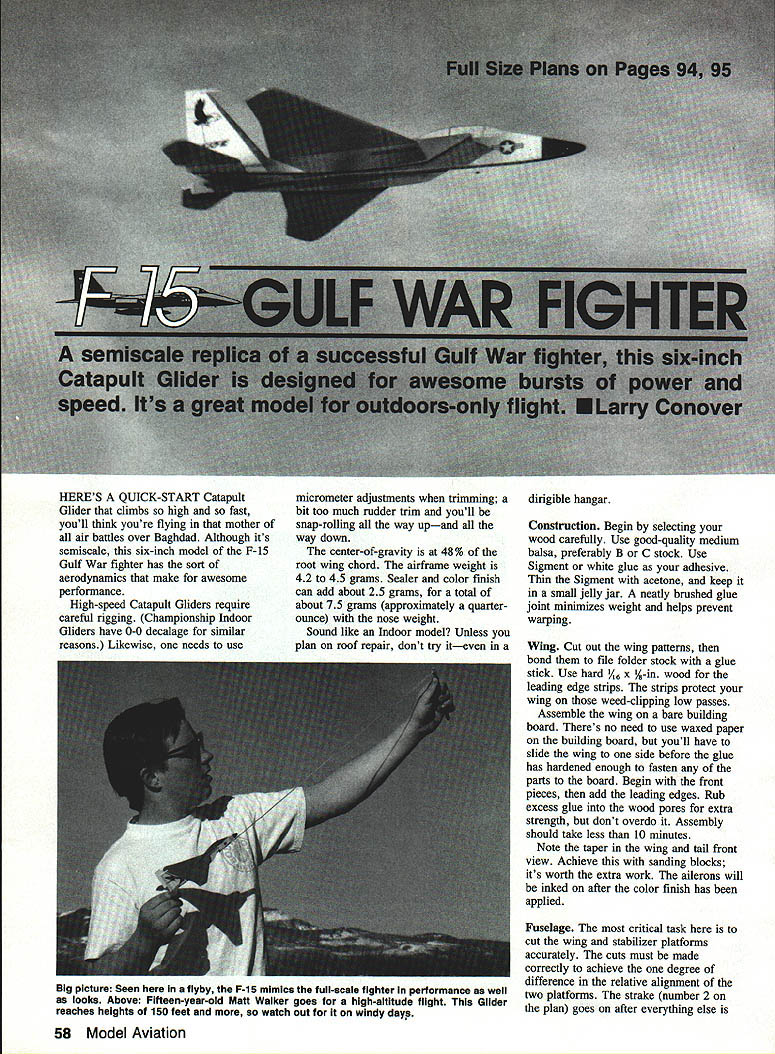
F-15 Gulf War Fighter
A semiscale replica of a successful Gulf War fighter, this six-inch catapult glider is designed for awesome bursts of power and speed. It's a great model for outdoors-only flight. — Larry Conover
Here's a quick-start catapult glider that climbs so high and so fast you'll think you're flying in that mother of all air battles over Baghdad. Although it's semiscale, this six-inch model of the F-15 Gulf War fighter has the aerodynamics that make for excellent performance.
High-speed catapult gliders require careful rigging. (Championship indoor gliders have 0°-0° decalage for similar reasons.) Likewise, use micrometer adjustments when trimming; a bit too much rudder trim and you'll be snap-rolling all the way up—and all the way down.
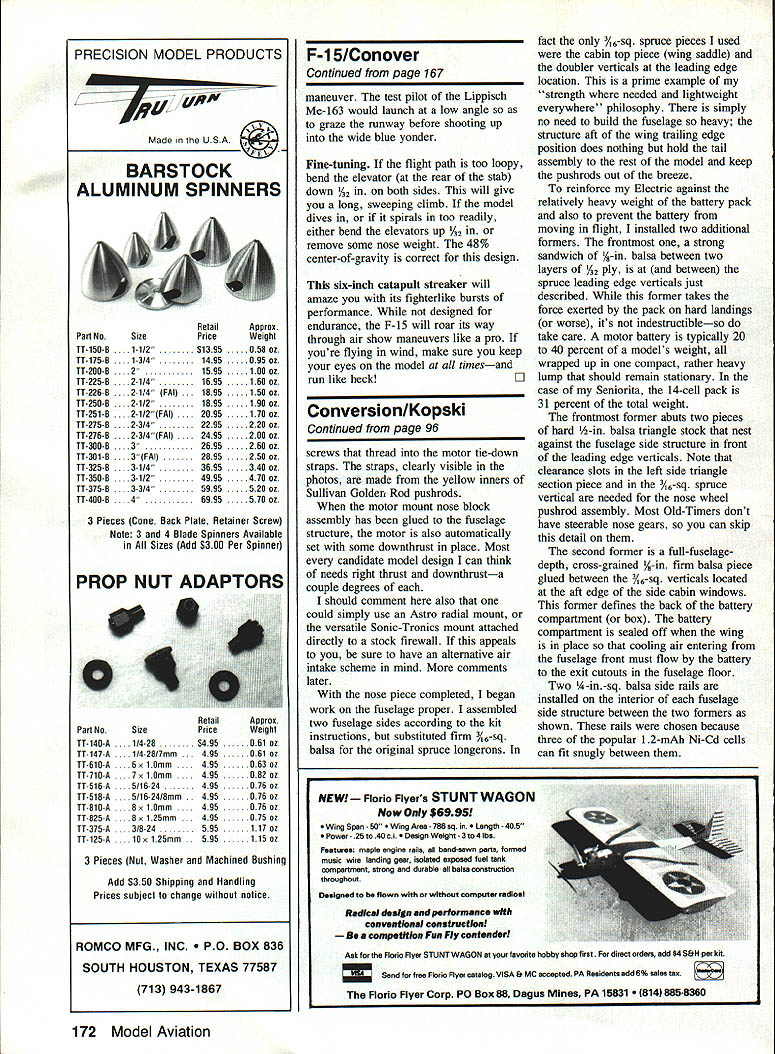
The center of gravity (CG) is at 48% of the root wing chord. The airframe weight is 4.2 to 4.5 grams. Sealer and color finish can add about 2.5 grams, for a total of about 7.5 grams (approximately a quarter-ounce) with the nose weight.
Sound like an indoor model? Unless you plan on roof repair, don't try it—even in a dirigible hangar.
Construction
Begin by selecting your wood carefully. Use good-quality medium balsa, preferably B or C stock. Use Sigment or white glue as your adhesive. Thin the Sigment with acetone, and keep it in a small jelly jar. A neatly brushed glue joint minimizes weight and helps prevent warping.
Wing
Cut out the wing patterns, then bond them to file-folder stock with a glue stick. Use hard 1/16 x 3/8 in. wood for the leading-edge strips. The strips protect your wing on those weed-clipping low passes.
Assemble the wing on a bare building board. There's no need to use waxed paper on the building board, but you'll have to slide the wing to one side before the glue has hardened enough to fasten any of the parts to the board. Begin with the front pieces, then add the leading edges. Rub excess glue into the wood pores for extra strength, but don't overdo it. Assembly should take less than 10 minutes.
Note the taper in the wing and tail front view. Achieve this with sanding blocks; it's worth the extra work. The ailerons will be inked on after the color finish has been applied.
Fuselage
The most critical task here is to cut the wing and stabilizer platforms accurately. The cuts must be made correctly to achieve the one-degree difference in relative alignment of the two platforms. The strake (number 2 on the plan) goes on after everything else is assembled.
Glue the strake (number 2) to the top of the wing. Coat the nose with glue as you fasten a 0.3-gram 1/32-sheet-lead balance weight to the nose. Trim the nose weight so that the model balances on scissor points at the 48% center of gravity.
Test-glide the model. The glide should be flat and fast. This is a delta-wing glider, not a soarer.
Empennage
The goal is to keep the tail as light as possible. The stabilizer (number 8 on the plan) can be left flat with no sanding, but you'll be much happier with the results if you take the trouble to contour it. Add the rear deck (number 6), keeping a close watch on the grain across the booms.
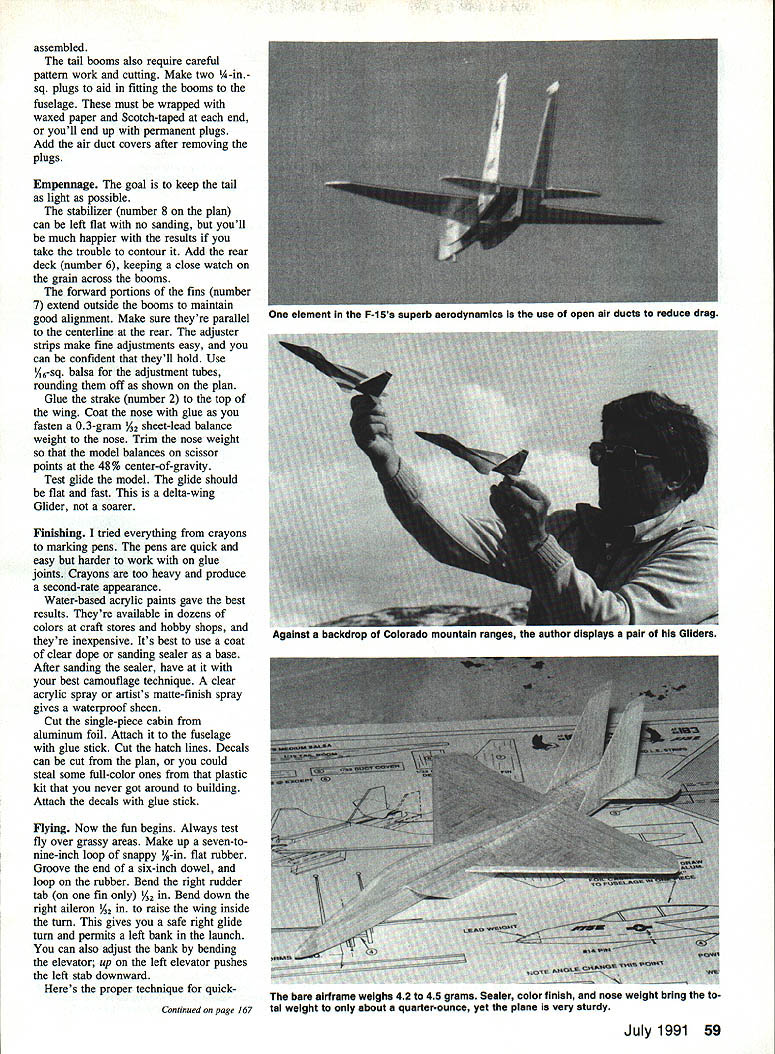
The forward portions of the fins (number 7) extend outside the booms to maintain good alignment. Make sure they're parallel to the centerline at the rear. The adjuster strips make fine adjustments easy, and you can be confident that they'll hold. Use 1/16-sq. balsa for the adjustment tubes, rounding them off as shown on the plan.
Finishing
I tried everything from crayons to marking pens. The pens are quick and easy but harder to work with on glue joints. Crayons are too heavy and produce a second-rate appearance.
Water-based acrylic paints gave the best results. They're available in dozens of colors at craft stores and hobby shops, and they're inexpensive. It's best to use a coat of clear dope or sanding sealer as a base. After sanding sealer, apply your best camouflage technique. A clear acrylic spray or artist's matte-finish spray gives a waterproof sheen.
Cut the single-piece cabin from aluminum foil. Attach it to the fuselage with a glue stick. Cut the hatch lines. Decals can be cut from the plan, or you could steal some full-color ones from that plastic kit that you never got around to building. Attach the decals with a glue stick.
Flying
Always test fly over grassy areas. Make up a 7- to 9-inch loop of snappy 1/8-in. flat rubber. Groove the end of a six-inch dowel, and loop on the rubber.
Bend the right rudder tab (on one fin only) 1/32 in. Bend down the right aileron 1/32 in. to raise the wing inside the turn. This gives you a safe right glide turn and permits a left bank in the launch. You can also adjust the bank by bending the elevator: up on the left elevator pushes the left stab downward.
Proper technique for quick-start launching:
- With the thumb and forefinger of your left hand, grip the stabilizer at the very back of the fuselage.
- Point the nose up about 45 degrees, and bank slightly to the left.
- Start with half-power launches, increasing power as you gain confidence.
As you increase power, you'll notice a change in the lift characteristics of delta wings. Both swept-back and delta wings have a critical flow change as they reach higher speeds: the center of pressure shifts and the airplane noses down. Overcome this drop in trajectory by elevating the nose more. (You could also execute a Heinie Dittmar maneuver — the test pilot of the Lippisch Me-163 would launch at a low angle so as to graze the runway before shooting up into the wide blue yonder.)
Fine-tuning:
- If the flight path is too loopy, bend the elevator (at the rear of the stab) down 1/32 in. on both sides. This will give you a long, sweeping climb.
- If the model dives in, or spirals in too readily, either bend the elevators up 1/32 in. or remove some nose weight. The 48% center-of-gravity is correct for this design.
This six-inch catapult streaker will amaze you with its fighterlike bursts of performance. While not designed for endurance, the F-15 will roar its way through air-show maneuvers like a pro. If you're flying in wind, keep your eyes on the model at all times—and run like heck!
Reinforcement and Battery Compartment (additional structural notes)
In my builds I used only two 3/16-in.-sq. spruce pieces: the cabin top piece (wing saddle) and the doubler verticals at the leading-edge location. This follows a "strength where needed and lightweight everywhere" philosophy. There is no need to build the fuselage excessively heavy; the structure aft of the wing trailing-edge mainly holds the tail assembly and keeps pushrods out of the breeze.
To reinforce an electric version against the relatively heavy weight of the battery pack and to prevent the battery from moving in flight, install two additional formers. The frontmost former is a strong sandwich: 1/8-in. balsa between two layers of 1/32-in. ply, located at (and between) the spruce leading-edge verticals described above. This former takes the force exerted by the pack on hard landings (or worse), though it's not indestructible—so take care. A motor battery is typically 20 to 40 percent of a model's weight, concentrated in one heavy lump that should remain stationary. In one example, a 14-cell pack was 31 percent of the total weight.
The frontmost former abuts two pieces of hard 1/2-in. balsa triangle stock that rest against the fuselage side structure in front of the leading-edge verticals. Note that clearance slots in the left-side triangle section piece and in the 3/16-in.-sq. spruce vertical are needed for the nose-wheel pushrod assembly. Most old-timer models don't have steerable nose gears, so you can skip this detail on them.
The second former is a full-fuselage-depth, cross-grained 1/8-in. firm balsa piece glued between the 3/16-in.-sq. verticals located at the aft edge of the side cabin windows. This former defines the back of the battery compartment (or box). The battery compartment is sealed off when the wing is in place so that cooling air entering from the fuselage front must flow by the battery to the exit cutouts in the fuselage floor.
Two 1/4-in.-sq. balsa side rails are installed on the interior of each fuselage side structure between the two formers as shown. These rails were chosen because three of the popular 1.2-Ah Ni-Cd cells can fit snugly between them.
Transcribed from original scans by AI. Minor OCR errors may remain.

