

F3B Technicalities
By John Dvorak
HOW CAN the average modeler benefit from a high-tech World Championships? How can sailplanes with the capacity to fly like rockets compete in duration and distance tasks? Can you catch a thermal in the rain?
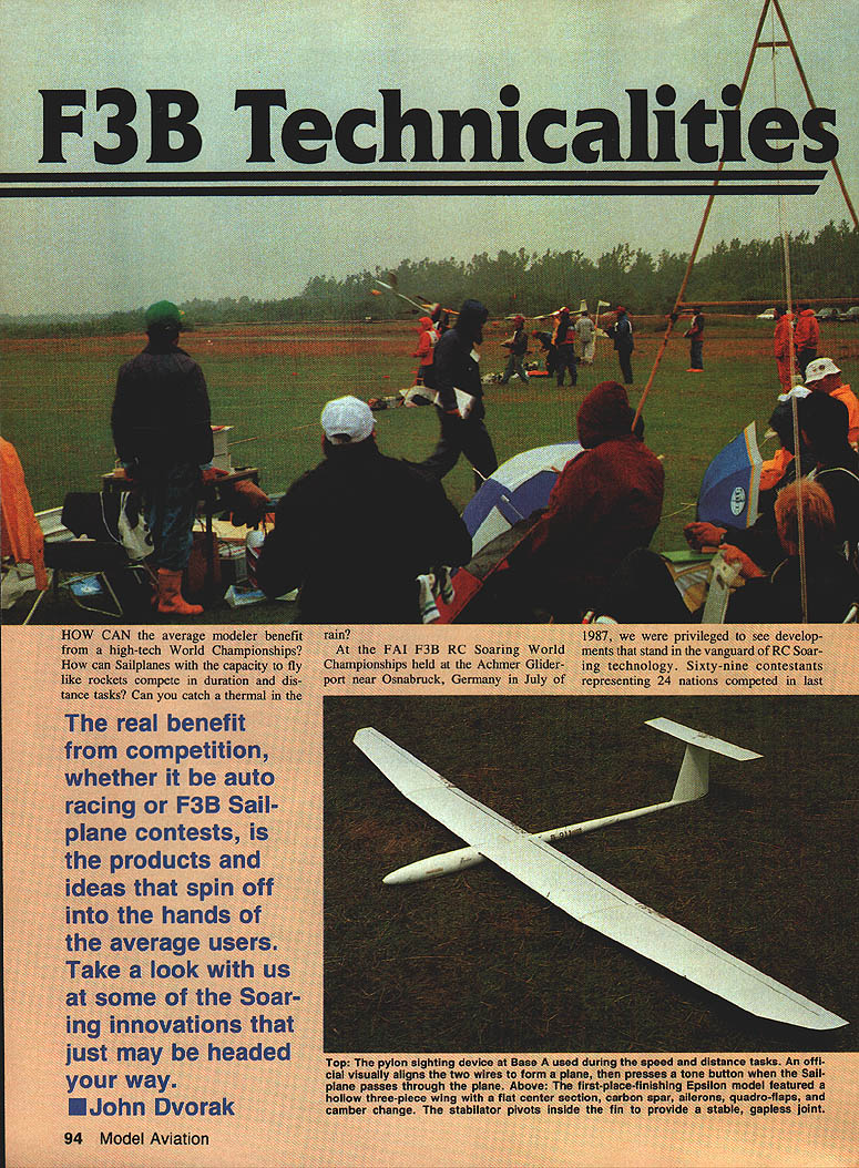
At the FAI F3B RC Soaring World Championships held at the Achmer Gliderport near Osnabrück, Germany in July 1987, we were privileged to see developments at the vanguard of RC soaring technology. Sixty-nine contestants representing 24 nations competed in the summer edition of this Olympics of RC Soaring. Pilots and crews came from all over the world with a multitude of innovations in sailplane design and equipment, and the resulting performance of these aircraft in many cases truly astounded us. They flew planes with hollow-shell glass wings, used flaps and ailerons that opened in opposite directions as brakes, withstood launches that would tear the wings off most planes, and rounded pylons at breathtaking speeds — all in the rain, with no engines and no fumes.
Planes • Pilots • Winches
- Team results and top pilots: Austria captured the first-place team trophy. Peter Hoffman (Austria) placed second flying his original-design Target. Great Britain finished second in the team standings; 19-year-old Stephen Haley flew his Merlin to a fourth-place finish. Germany placed third as a team, and Reinhard Leise (Germany) was the individual champion flying his Epsilon. Switzerland placed fifth as a team; the United States finished seventh.
- Notable performances: Peter Abell (Australia) flew the standout LB4 and led at the end of Round Three; his LB4 was nearly destroyed, rebuilt overnight, and completed the round. Samuele Villani (Italy) placed sixth. Josef Loepp (Czechoslovakia) flew the Jewel, which was voted by the press as the best-looking and most innovative design.
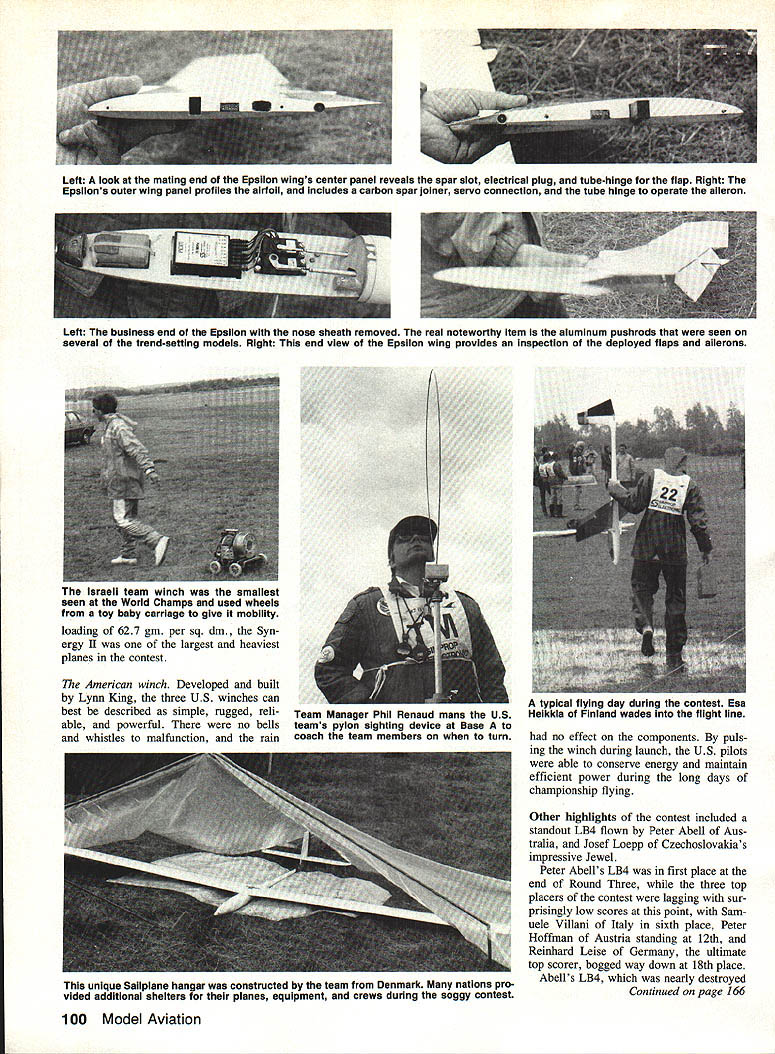
Epsilon — wing construction
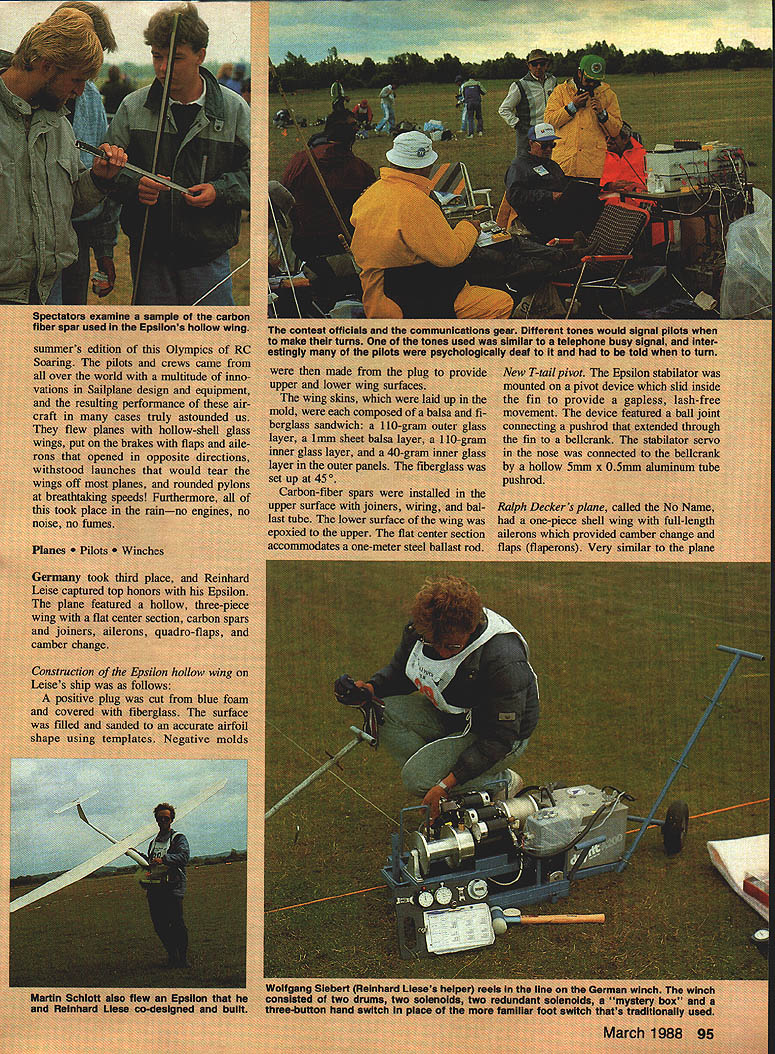
Reinhard Leise’s Epsilon featured a hollow, three-piece wing with a flat center section, carbon spars and joiners, ailerons, quadro-flaps, and camber change. Construction details:
- A positive plug was cut from blue foam and covered with fiberglass.
- The surface was filled and sanded to an accurate airfoil shape using templates.
- Negative molds were made from the plug to form upper and lower wing surfaces.
- Wing skins were laid up in the molds as a balsa-and-fiberglass sandwich: a 110-gram outer glass layer, 1 mm balsa sheet, a 110-gram inner glass layer, and a 40-gram inner glass layer in the outer panels. The fiberglass was oriented at 45°.
- Carbon-fiber spars were installed in the upper surface with joiners, wiring, and a ballast tube.
- The lower surface of the wing was epoxied to the upper. The flat center section accommodates a one-meter steel ballast rod.
New T-tail pivot
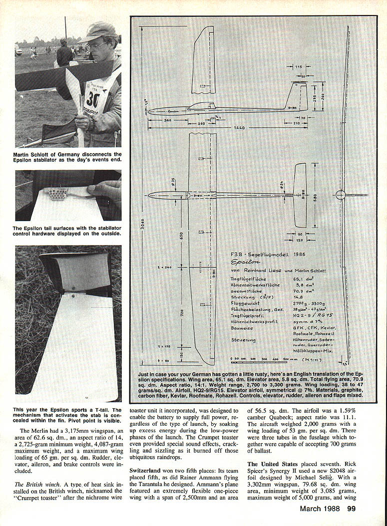
The Epsilon stabilator was mounted on a pivot device that slid inside the fin to provide gapless, lash-free movement. The device featured a ball joint connecting a pushrod that extended through the fin to a bellcrank. The stabilator servo in the nose was connected to the bellcrank by a hollow 5 mm × 0.5 mm aluminum tube pushrod. This arrangement produced a wobble-free T-tail with concealed mechanism.
One Decker design that had flown to first-place wins in 1983 and 1985 appeared in a new variant with a beefed-up carbon spar and a 2.5% camber airfoil. The fuselage was constructed of molded fiberglass and Kevlar.
Winches
- German winch: The German team provided three sophisticated and powerful winches. Each used two counter-rotating drums so the winch line unwound off the top; motors had redundant solenoids. The drum and motor frame were mounted on springs, possibly part of a line-tension sensing device. A "mystery box" on the German winch allowed fine-tuning for varying launch conditions: a hand-held switch offered full zoom power, reduced kiting power, and low power for reeling in the line.
- Line-tension sensing: Several teams used simple line-tension sensors placed about 10 meters from the winches. These were on-off switches connected to pulley wheels; when a preset tension was exceeded the motor was momentarily switched off or pulsed.
- British winch: The British winch incorporated a type of heat sink nicknamed the "Crumpet toaster." It soaked up excess energy during low-power phases of the launch so the battery could supply full power when needed. The unit even produced crackling and sizzling sounds as it burned off raindrops.
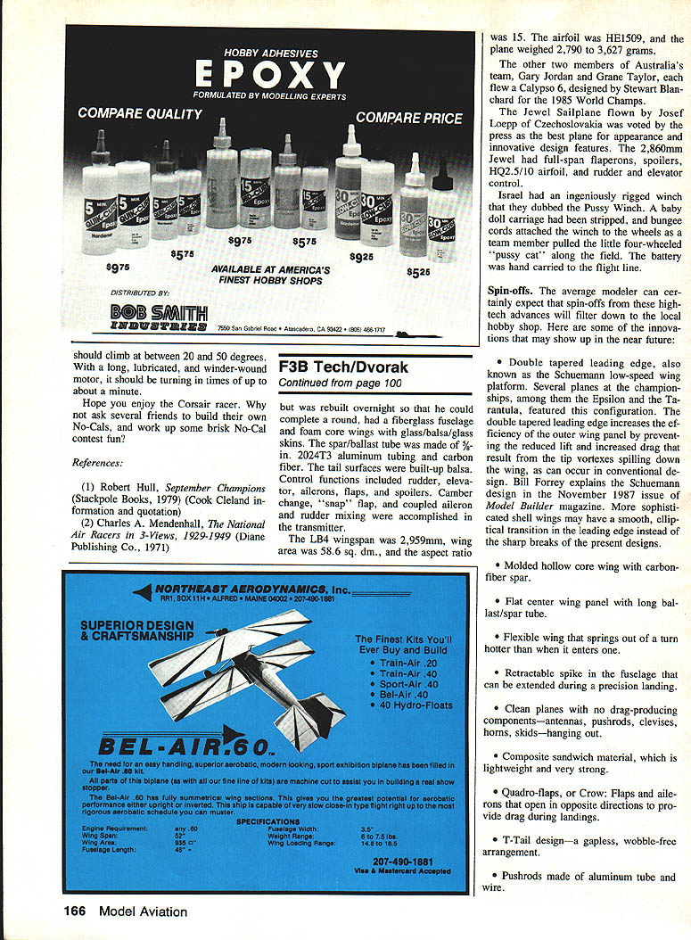
- Israeli winch: Israel fielded the smallest winch, rigged ingeniously using wheels from a toy baby carriage for mobility. The team also used a small, improvised winch they dubbed the "Pussy Winch," carrying the battery to the flight line by hand.
- American winch: Designed and built by Lynn King, the three U.S. winches were simple, rugged, reliable, and powerful. They had few failure points and were unaffected by rain. By pulsing the winch during launch, U.S. pilots conserved energy and maintained efficient power during long championship days.
Notable aircraft and technical details
- Target (Peter Hoffman, Austria): 2,900 mm wingspan; Giersberg 14 airfoil; area 63.3 sq. dm.; aspect ratio 13.18; minimum weight 2,700 g; maximum weight 4,700 g; maximum wing loading 67.5 g per sq. dm. The one-piece Target wing had four servos for flaps, ailerons, and camber change. The ailerons extended through the wingtips.
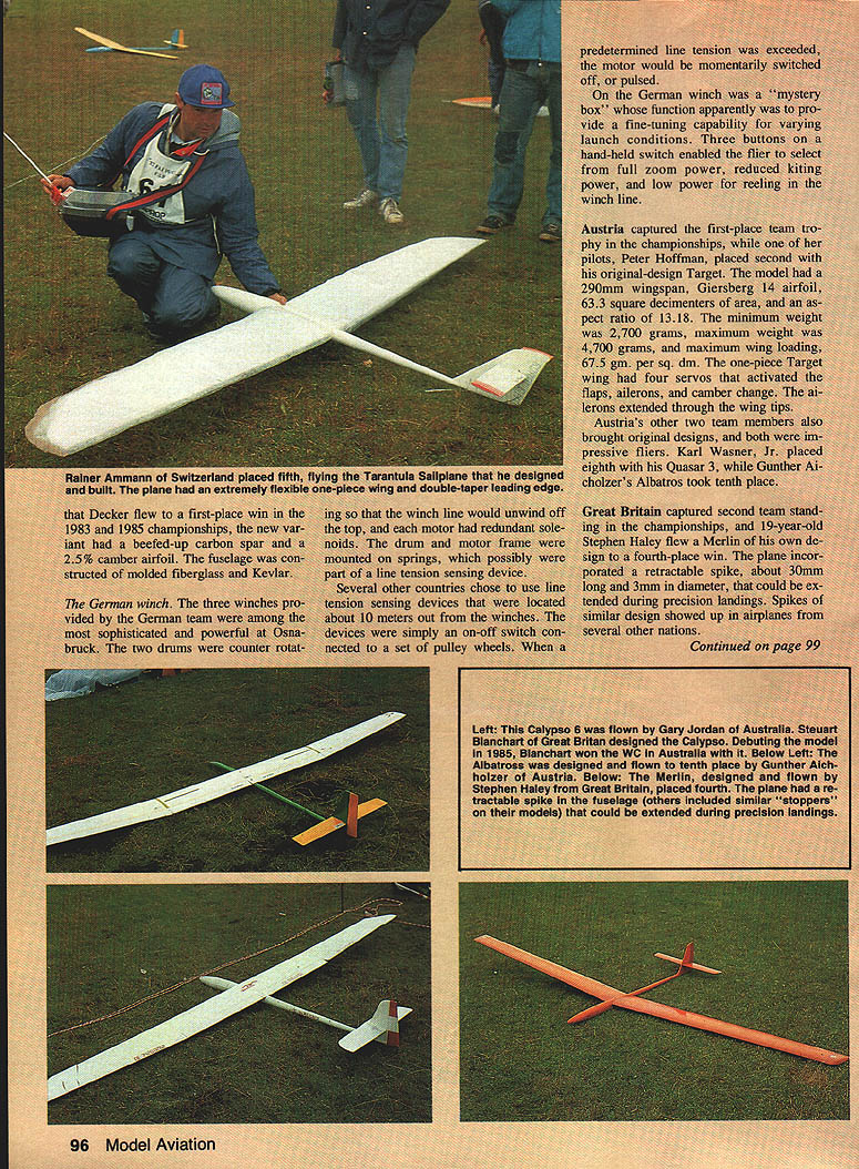
- Merlin (Stephen Haley, Great Britain): 3,175 mm wingspan; area 62.6 sq. dm.; aspect ratio 14; minimum weight 2,725 g; maximum weight 4,087 g; maximum wing loading 65 g per sq. dm. Controls included rudder, elevator, aileron, and brakes. The Merlin incorporated a retractable spike (approx. 30 mm long, 3 mm diameter) that could be extended for precision landings; similar spikes appeared on models from several nations.
- Tarantula (Rainer Ammann, Switzerland): Extremely flexible one-piece wing; 2,500 mm span; area 56.5 sq. dm.; Quabeck airfoil with 1.59% camber; aspect ratio 11.1; aircraft weight 2,000 g; wing loading 63 g per sq. dm. Three tubes in the fuselage accept up to 700 g of ballast.
- Synergy II (Rick Spicer, USA): Used the S2048 airfoil designed by Michael Selig; 3,302 mm wingspan; wing area 79.68 sq. dm.; minimum weight 3,085 g; maximum weight 5,000 g; wing loading 65 g per sq. dm.
- LB4 (Peter Abell, Australia): Fiberglass fuselage and foam-core wings with glass/balsa/glass skins; spar/ballast tube made of 5/16-inch 2024-T3 aluminum tubing and carbon fiber; built-up balsa tail surfaces. Control functions included rudder, elevator, aileron, flaps, and spoilers. Camber change, "snap" flap, and coupled aileron/rudder mixing were programmed in the transmitter. Wingspan 2,959 mm; wing area 58.6 sq. dm.; aspect ratio 15; HE1509 airfoil; weight 2,790–3,627 g.
- Jewel (Josef Loepp, Czechoslovakia): 2,860 mm wingspan; full-span flaperons and spoilers; HQ2.5/10 airfoil; rudder and elevator control. Voted best appearance and innovative design by the press.
Other noteworthy entries included the Calypso 6 (Gary Jordan and Grane Taylor, Australia) designed by Stewart Blanchard for the 1985 World Champs.
Spin-offs — what the average modeler can expect
The real benefit of competition is the technology and ideas that spin off into the hands of everyday modelers. Innovations from the 1987 World Championships likely to appear in hobby shops include:
- Double-tapered leading edge (Schuemann low-speed wing platform) to improve outer-panel efficiency and reduce tip-vortex spill-down. More sophisticated versions may use a smooth, elliptic transition rather than sharp breaks.
- Molded hollow-core wings with carbon-fiber spars.
- Flat center wing panels with long ballast/spar tubes.
- Flexible wings that "spring out" of a turn hotter than when they entered it.
- Retractable fuselage spike for precision landings.
- Clean airframe detailing to eliminate drag-producing external items (antennas, exposed pushrods, clevises, horns, skids).
- Composite sandwich construction for lightweight strength.
- Quadro-flaps (Crow): flaps and ailerons that open in opposite directions to increase drag during landings.
- T-tail designs with gapless, wobble-free pivots.
- Pushrods made from aluminum tubing with internal wire.
- Winch line-tension sensing to adapt launches to wind conditions and to a range of planes.
- Extensive transmitter mixing of all sailplane control functions.
- New flying techniques and contest tricks for operating in adverse weather and under stress — tips that will be passed on to everyday fliers.
For previewing the future of RC soaring, Germany in July 1987 was the place to be.
Transcribed from original scans by AI. Minor OCR errors may remain.

