
Fabricate That: Special Fuel Tank
By Clarence Haught
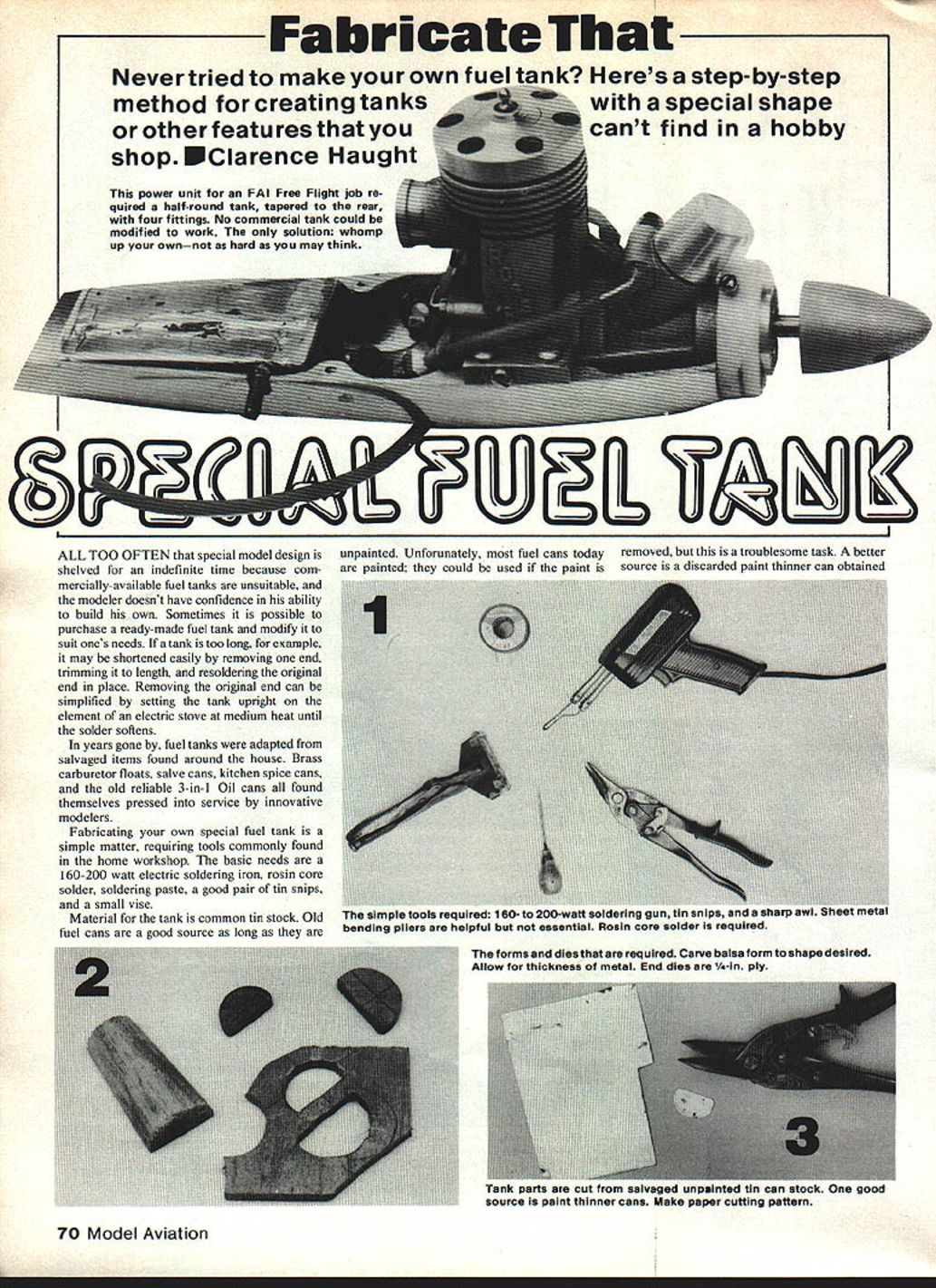
Never tried to make your own fuel tank? Here's a step-by-step method for creating tanks with a special shape or other features that you can't find in a hobby shop. This power unit for an FAI Free Flight project required a half-round tank, tapered to the rear, with four fittings. No commercial tank could be modified to work. The only solution: whip up your own—not as hard as you may think.
Introduction
All too often a special model design is shelved because commercially available fuel tanks are unsuitable and the modeler lacks confidence to build a custom tank. Sometimes a ready-made tank can be modified (for example, shorten a tank by removing one end, trimming it to length, and resoldering the original end). Removing the original end can be simplified by setting the can upright on the heating element of an electric stove at medium heat until the solder softens.
In years gone by, tanks were adapted from salvaged items around the house: brass carburetor floats, salve cans, kitchen spice tins, and the old reliable 3-in-One oil cans. Today, common tin stock remains the best material for fabricating special tanks.
Tools and Materials
- 160–200 watt electric soldering iron
- Rosin-core solder
- Soldering paste (flux)
- Good pair of tin snips
- Small vise
- Tin stock (salvaged unpainted cans or discarded paint thinner cans)
- Can opener
- Awl or sharp punch
- Fuel tubing and fittings
- Fuel syringe (for leak testing)
- Silicone sealant (for installation)
Notes on material sources:
- Old fuel cans are good if unpainted. If painted, paint must be removed (troublesome).
- A discarded paint thinner can from an auto body shop is a good source.
- Paper labels come off readily after an overnight soak in water with a spoonful of dishwashing detergent.
- Food cans are generally unsuitable because of internal coatings.
Preparing the Can
- Use a can opener to cut out the top and bottom.
- Cut out the soldered side seam with tin snips.
- Remove reinforcing beads from the top and bottom edges.
- Clean off paper labels after soaking (see Materials).
This produces flat tin stock you can form into the shape you need.
Forming Ends and Lap Joints
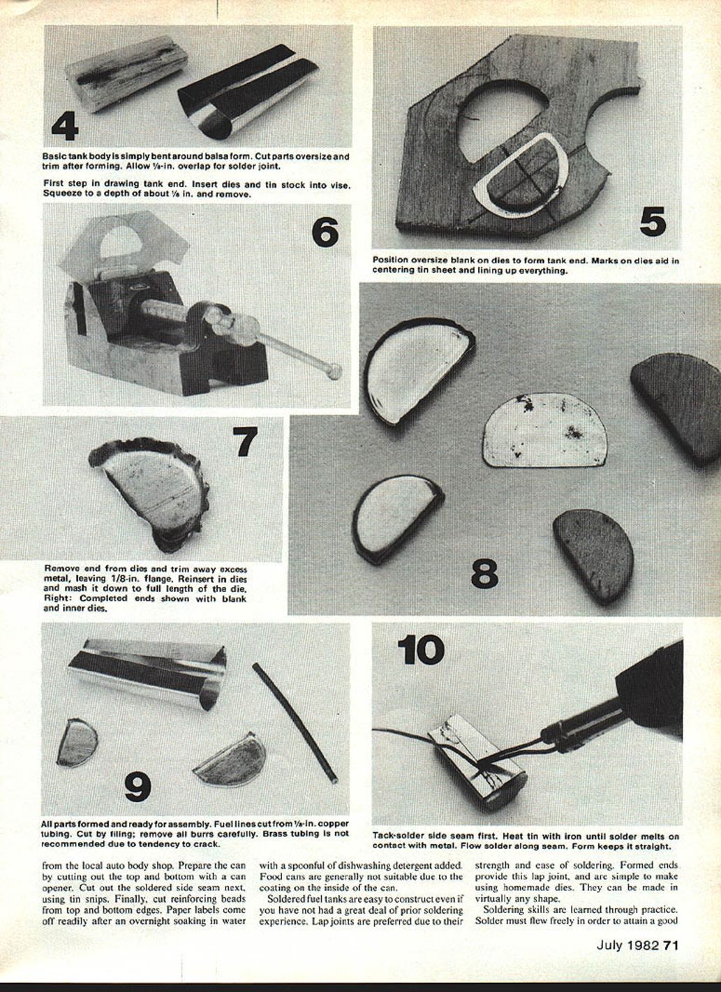
Lap joints are preferred for strength and ease of soldering. Formed ends provide the lap joint and are simple to make using homemade dies. Ends can be formed in virtually any shape to suit your tank design.
Soldering basics:
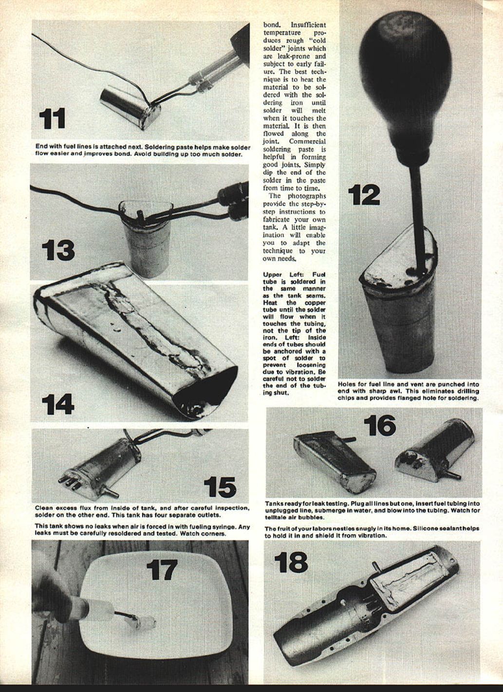
- Solder must flow freely to form a good bond. Insufficient temperature produces rough "cold solder" joints that are leak-prone and subject to early failure.
- Heat the material to be soldered with the iron until solder will melt when it touches the material (not just the iron tip). Then flow the solder along the joint.
- Commercial soldering paste helps form good joints—dip the solder in the paste from time to time.
- Practice improves technique.
Assembling the Tank
- Use lap joints for seams; solder thoroughly for a continuous bond.
- After completing one side, clean excess flux from the inside of the tank, inspect carefully, and solder on the other end.
- Avoid building up too much solder; neat, continuous seams are best.
Fitting Fuel Lines and Vent
- Holes for fuel lines and the vent are best punched into the end with a sharp awl. Punching eliminates drilling chips and provides a flanged hole for soldering.
- Fuel tubing is soldered in the same manner as tank seams. Heat the copper tube until solder will flow when it touches the tubing (heat the tubing, not the tip of the iron).
- Inside ends of tubes should be anchored with a spot of solder to prevent loosening due to vibration. Be careful not to solder the end of the tubing shut.
- Soldering paste helps solder flow and improves the bond.
Leak Testing
- Plug all lines but one.
- Insert fuel tubing into the unplugged line.
- Submerge the tank in water and blow into the tubing (or force air in with a fueling syringe).
- Watch for telltale air bubbles indicating leaks.
- Any leaks must be carefully resoldered and retested—pay attention to corners.
Tanks ready for testing should show no bubbles when air is forced in.
Installation and Final Notes
- After successful leak testing and final inspection, install the tank in its location.
- Silicone sealant helps hold the tank in place and shields it from vibration.
- A little imagination allows you to adapt these techniques to suit different shapes and outlet configurations (the example tank has four separate outlets).
Photograph Notes (original captions and tips)
- Fuel tube is soldered in the same manner as the tank seams. Heat the copper tube until solder will flow when it touches the tubing, not the tip of the iron.
- Inside ends of tubes should be anchored with a spot of solder to prevent loosening due to vibration—be careful not to solder the tubing shut.
- Punch holes with a sharp awl to avoid chips and to form a flanged hole for soldering.
- Clean excess flux from inside the tank before final soldering.
- Use a fueling syringe or blow into a single open line while submerged to test for leaks.
- Once installed, silicone sealant helps cushion the tank and reduce vibration.
Transcribed from original scans by AI. Minor OCR errors may remain.

