
The Fairchild FC-2
George H. Clapp
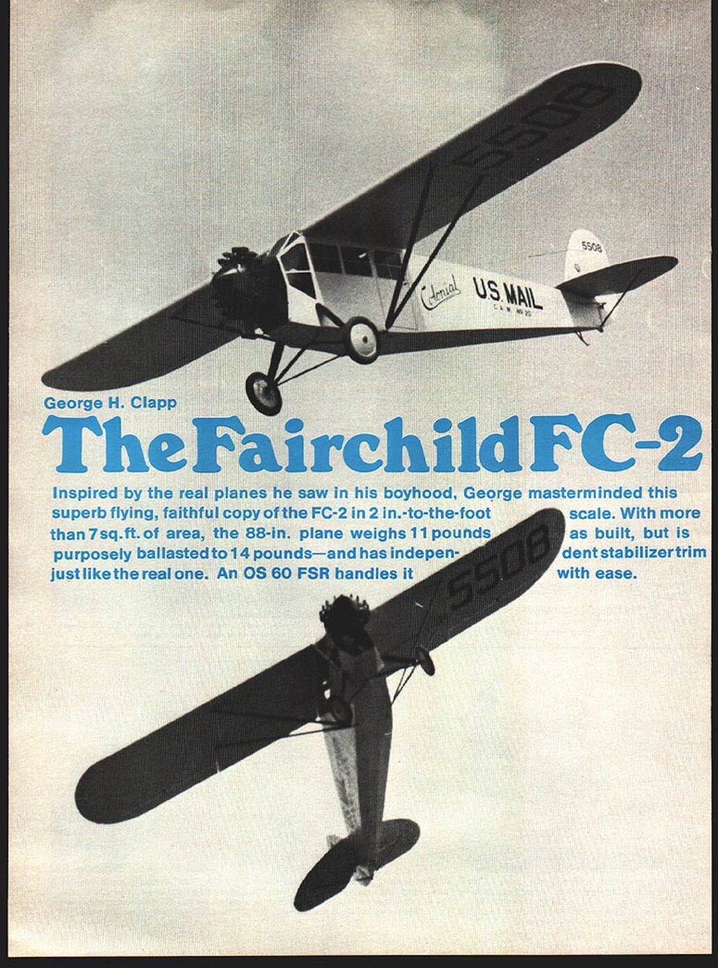
Inspired by the real planes he saw in his boyhood, George masterminded this superb flying, faithful copy of the FC-2 in 2‑in.‑to‑the‑foot scale. With more than 7 sq. ft. of area, the 88‑in. plane weighs 11 pounds as built, but is purposely ballasted to 14 pounds—and has independent stabilizer trim just like the real one. An O.S. 60 FSR handles it with ease.
The morning was gray with overcast skies but the heavy rain of the afternoon before had turned to a drizzle and visibility was much better at the old Syracuse Amboy Airport. The Colonial Western C.A.M. 20 flight of yesterday had been grounded by the weather but now was ready to continue its journey west to Cleveland. The pilot ground‑checked his Fairchild FC‑2, taxied out and stopped, facing downwind to check the magnetos and clear himself of any landing aircraft.
His payload was mail only, without passengers to keep him company, as he swung the big Fairchild into the wind and pushed the throttle forward to begin the takeoff run. With this light load, the aircraft normally was airborne right away and he had shortened the takeoff run because of this. The tail came up right off as usual, but the Whirlwind did not seem to move the ship out in the normal fashion. With the airspeed showing takeoff momentum, the pilot drew back on the stick for lift‑off. The point of no return was now past but the FC‑2 would not leave the ground. The pilot had no choice but to cut the switches and ride the aircraft off the field into a swamp of tree stumps at the northwest end of the Amboy Airport.
The Fairchild was heavily damaged but the pilot's ego was hurt more than anything. He had not checked the drains on the wings' lower trailing edge and both wings were full of rain water on takeoff.
I remember the incident being written up in the Syracuse newspapers and, while talking to Cy Bittner (who flew 5508 at one time for Colonial), he also remembered it, but who the pilot was and the exact date are lost in time.
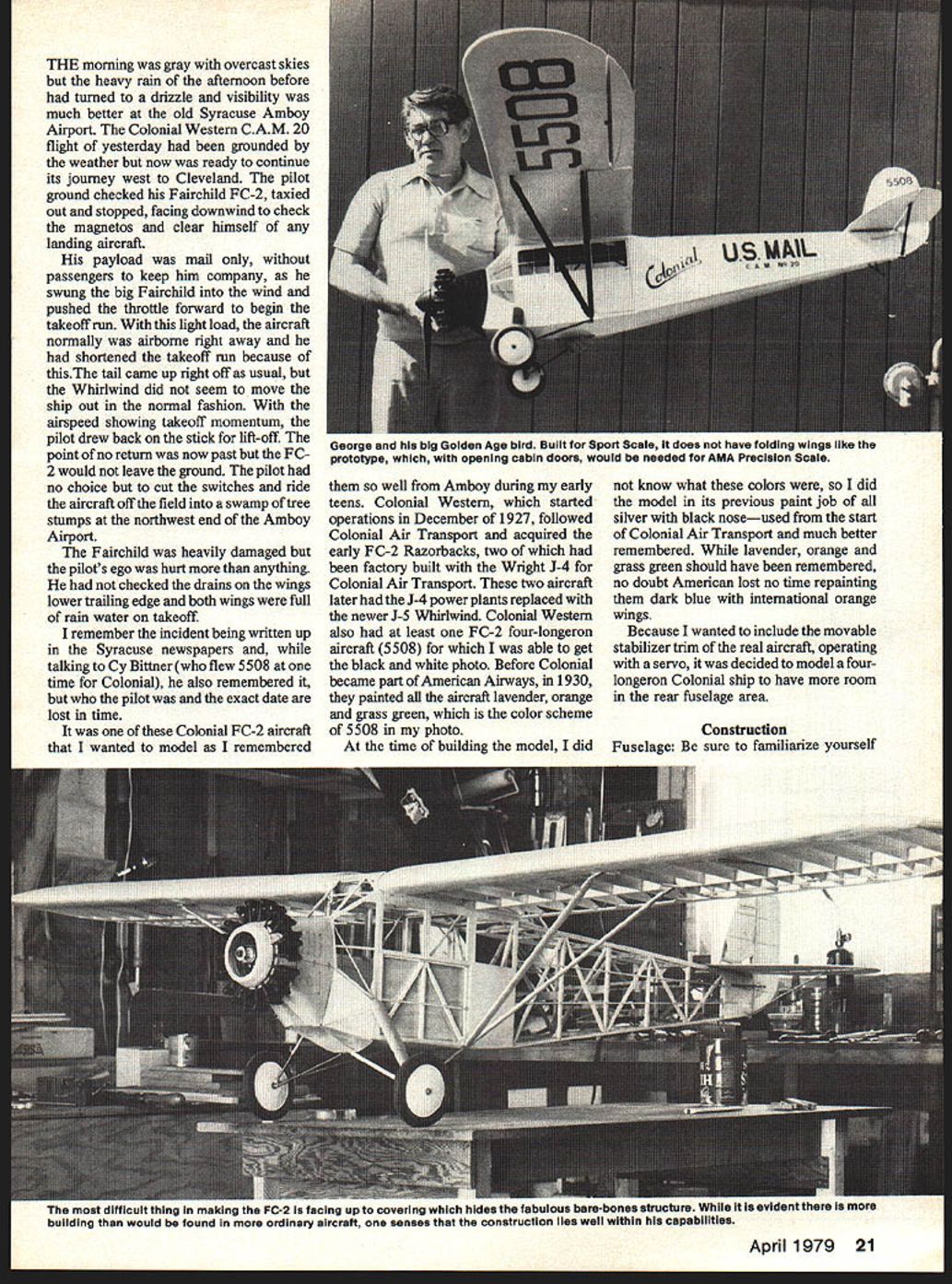
It was one of these Colonial FC‑2 aircraft that I wanted to model as I remembered them so well from Amboy during my early teens. Colonial Western, which started operations in December of 1927, followed Colonial Air Transport and acquired the early FC‑2 Razorbacks, two of which had been factory built with the Wright J‑4 for Colonial Air Transport. These two aircraft later had the J‑4 power plants replaced with the newer J‑5 Whirlwind. Colonial Western also had at least one FC‑2 four‑longeron aircraft (5508) for which I was able to get the black‑and‑white photo. Before Colonial became part of American Airways in 1930, they painted all the aircraft lavender, orange and grass green, which is the color scheme of 5508 in my photo.
At the time of building the model, I did not know what these colors were, so I did the model in its previous paint job of all silver with a black nose—used from the start of Colonial Air Transport and much better remembered. While lavender, orange and grass green should have been remembered, no doubt American lost no time repainting them dark blue with international orange wings.
Because I wanted to include the movable stabilizer trim of the real aircraft, operating with a servo, it was decided to model a four‑longeron Colonial ship to have more room in the rear fuselage area.
Construction
Fuselage
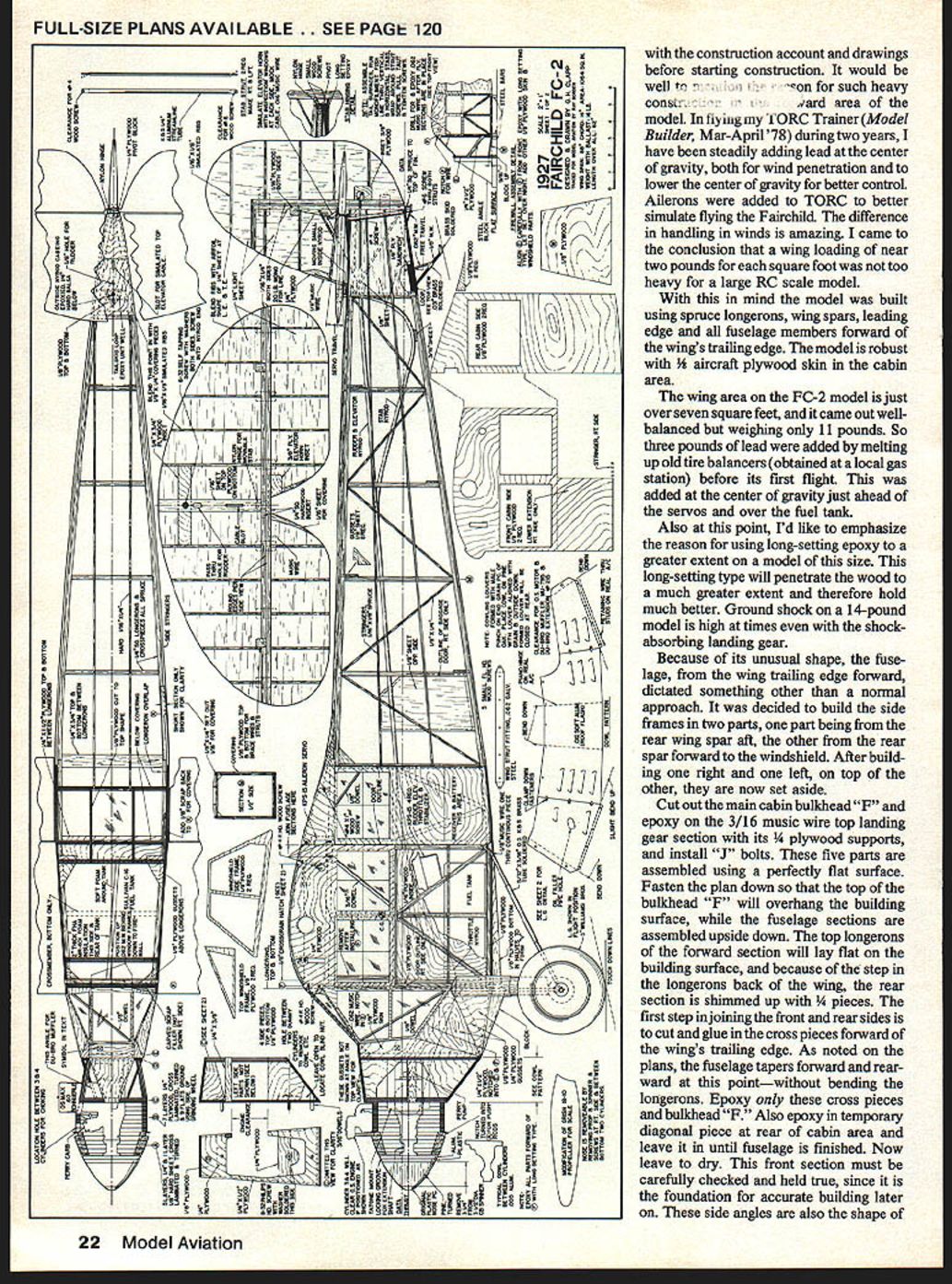
Be sure to familiarize yourself with the construction account and drawings before starting. It would be well to obtain the plan for such heavy construction in the forward area of the model. In flying my TORC Trainer (Model Builder, Mar–Apr '78) during two years, I have been steadily adding lead at the center of gravity, both for wind penetration and to lower the center of gravity for better control. Ailerons were added to TORC to better simulate flying the Fairchild. The difference in handling in winds is amazing. I came to the conclusion that a wing loading of near two pounds per square foot was not too heavy for a large RC scale model.
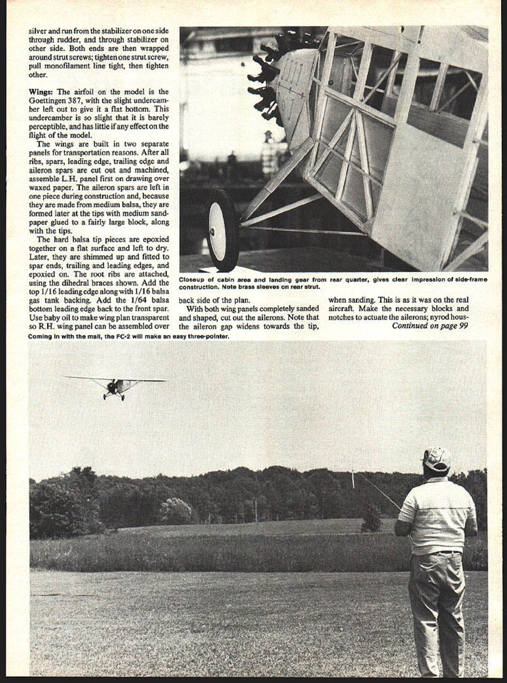
With this in mind the model was built using spruce longerons, wing spars, leading edge and all fuselage members forward of the wing's trailing edge. The model is robust with 1/16" aircraft plywood skin in the cabin area.
The wing area on the FC‑2 model is just over seven square feet, and it came out well balanced but weighing only 11 pounds. So three pounds of lead were added by melting up old tire balancers (obtained at a local gas station) before its first flight. This was added at the center of gravity just ahead of the servos and over the fuel tank.
Also at this point, I'd like to emphasize the reason for using long‑setting epoxy to a greater extent on a model of this size. This long‑setting type will penetrate the wood to a much greater extent and therefore hold much better. Ground shock on a 14‑pound model is high at times even with shock‑absorbing landing gear.
Because of its unusual shape, the fuselage from the wing trailing edge forward dictated something other than a normal approach. It was decided to build the side frames in two parts: one part from the rear wing spar aft, the other from the rear spar forward to the windshield. After building one right and one left, set them aside.
Cut out the main cabin bulkhead "F" and epoxy on the 3/16" music‑wire top landing gear section with its 1/4" plywood supports, and install the "J" bolts. These parts are assembled using a perfectly flat surface. Fasten the plan down so that the top of bulkhead "F" will overhang the building surface, while the fuselage sections are assembled upside down. The top longerons of the forward section will lay flat on the building surface, and because of the step in the longerons back of the wing, the rear section is shimmed up with 1/8" pieces.
The first step in joining the front and rear sides is to cut and glue in the cross pieces forward of the wing's trailing edge. As noted on the plans, the fuselage tapers forward and rearward at this point—without bending the longerons. Epoxy only these cross pieces and bulkhead "F." Also epoxy in a temporary diagonal piece at the rear of the cabin area and leave it in until the fuselage is finished. Now leave to dry. This front section must be carefully checked and held true, since it is the foundation for accurate building later on. These side angles are also the shape of the cabin side windows.
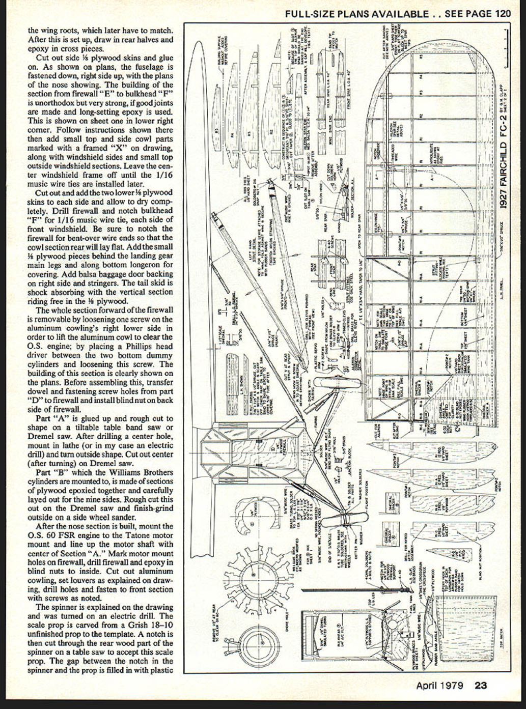
After this is set up, draw in the rear halves and epoxy in the remaining cross pieces. Remove the fuselage from the board and add the bottom sheeting of 1/16" balsa. When dry, add the side skins of 1/16" and sand to fair the cabin shape. The windshield cut‑out must be done before adding the top sheeting. At this time attach the cab top and glazing in the cockpit area.
Cut out and add the two lower 1/8" plywood skins to each side and allow to dry completely. Drill the firewall and notch bulkhead "F" for the 1/16" music‑wire ties, one on each side of the front windshield. Be sure to notch the firewall for bent‑over wire ends so that the cowl section rear will lay flat. Add the small 1/8" plywood pieces behind the landing gear main legs and along the bottom longeron for covering. Add balsa baggage door backing on the right side and stringers. The tail skid is shock absorbing with the vertical section riding free in the 1/8" plywood.
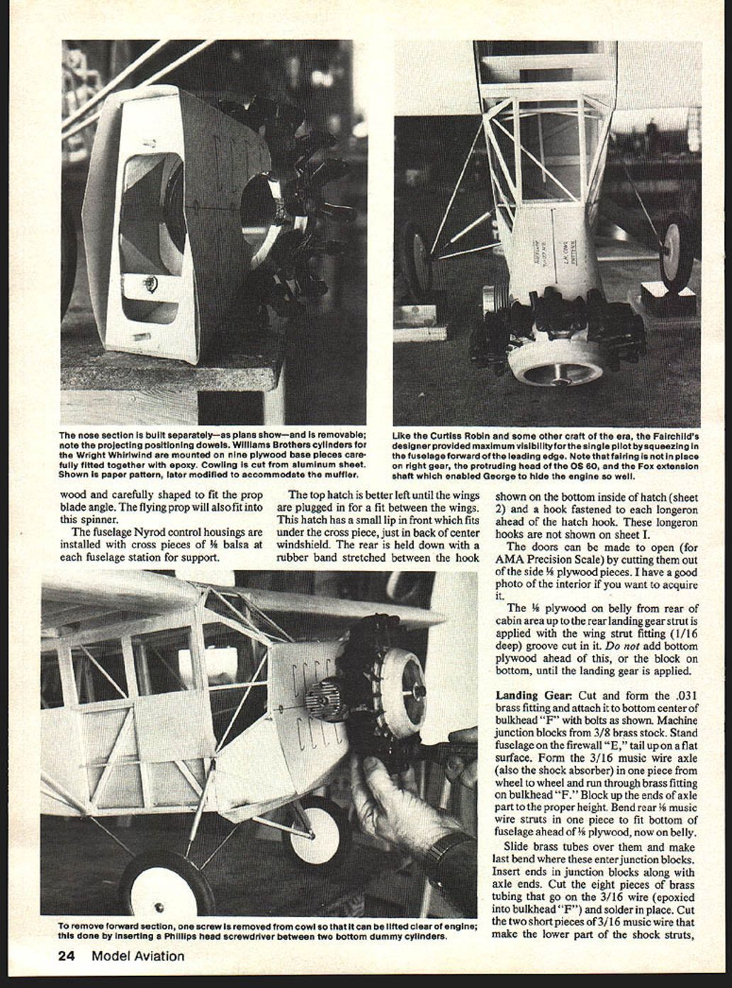
The whole section forward of the firewall is removable by loosening one screw on the aluminum cowling's right lower side in order to lift the aluminum cowl to clear the O.S. engine; place a Phillips head driver between the two bottom dummy cylinders and loosen this screw. The building of this section is clearly shown on the plans. Before assembling this, transfer dowel and fastening screw holes from part "D" to the firewall and install the blind nut on the back side of the firewall.
Part "A" is glued up and rough cut to shape on a tiltable table band saw or Dremel saw. After drilling a center hole, mount in a lathe (or in my case an electric drill) and turn the outside shape. Cut out the center (after turning) on a Dremel saw.
Part "B," which the Williams Brothers cylinders are mounted to, is made of sections of plywood epoxied together and carefully laid out for the nine sides. Rough cut this out on the Dremel saw and finish‑grind the outside on a side wheel sander.
After the nose section is built, mount the O.S. 60 FSR engine to the Tatone motor mount and line up the motor shaft with the center of section "A." Mark motor mount holes on the firewall, drill the firewall and epoxy in blind nuts to the inside. Cut out the aluminum cowling, set louvers as explained on the drawing, drill holes and fasten to the front section with screws as noted.
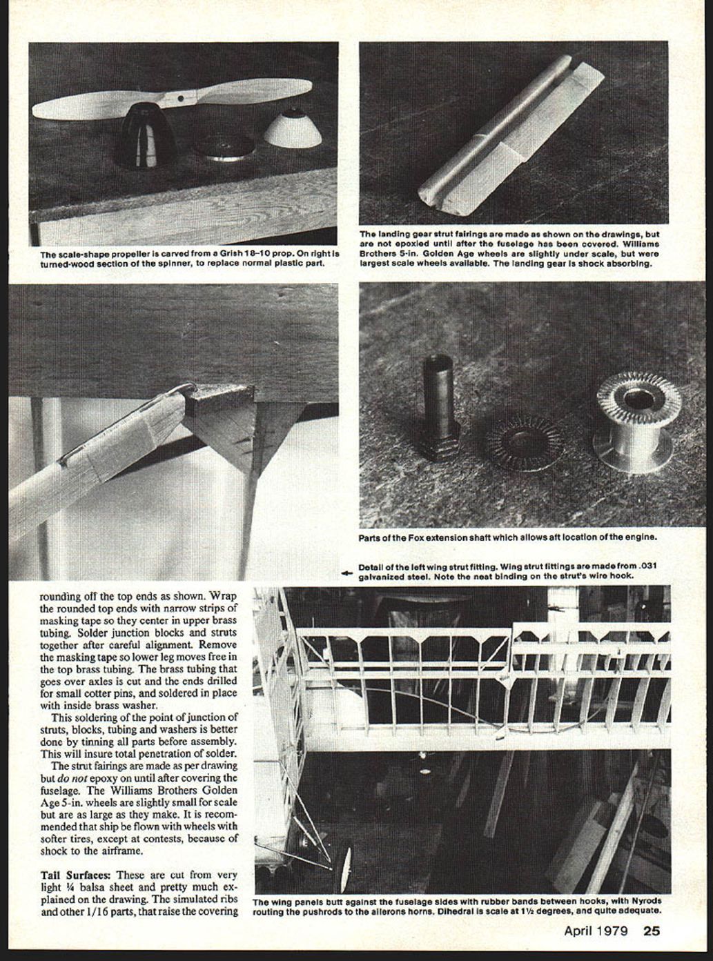
The spinner is explained on the drawing and was turned on an electric drill. The scale prop is carved from a Grish 18‑10 unfinished prop to the template. A notch is then cut through the rear wood part of the spinner on a table saw to accept this scale prop. The gap between the notch in the spinner and the prop is filled in with plastic Bondo. Screw the prop to the engine flange and sand the spinner to fit. The prop blades were carefully shaped to fit the spinner and the flying prop will also fit into this spinner.
The fuselage Nyrod control housings are installed with cross pieces of 1/8" balsa at each fuselage station for support.
The top hatch is better left until the wings are plugged in for a fit between the wings. This hatch has a small lip in front which fits under the cross piece just behind the center windshield. The rear is held down with a rubber band stretched between the hook shown on the bottom inside of the hatch and a hook fastened to each longeron ahead of the hatch hook. These longeron hooks are not shown on sheet 1.
The doors can be made to open (for AMA Precision Scale) by cutting them out of the side 1/8" plywood pieces. I have a good photo of the interior if you want to acquire it.
The 1/8" plywood on the belly from the rear of the cabin area up to the rear landing gear strut is applied with the wing strut fitting (1/16" deep) groove cut in it. Do not add bottom plywood ahead of this, or the block on the bottom, until the landing gear is applied.
Landing Gear
Cut and form the .031" brass fitting and attach it to the bottom center of bulkhead "F" with bolts as shown. Machine junction blocks from 3/8" brass stock. Stand the fuselage on the firewall "E", tail up on a flat surface. Form the 3/16" music‑wire axle (also the shock absorber) in one piece from wheel to wheel and run it through the brass fitting on bulkhead "F". Block up the ends of the axle to the proper height. Bend the rear 1/8" music‑wire struts in one piece to fit the bottom of the fuselage ahead of the 1/8" plywood now on the belly.
Slide brass tubes over them and make the last bend where these enter the junction blocks. Insert ends in junction blocks along with axle ends. Cut the eight pieces of brass tubing that go on the 3/16" wire (epoxied into bulkhead "F") and solder in place. Cut the two short pieces of 3/16" music wire that make the lower part of the shock struts, and solder these into the brass tubing.
Round off the top ends as shown and wrap the rounded top ends with narrow strips of masking tape so they center in the upper brass tubing. Solder junction blocks and struts together after careful alignment. Remove the masking tape so the lower leg moves free in the top brass tubing. The brass tubing that goes over the axles is cut, the ends drilled for small cotter pins, and soldered in place with an inside brass washer.
This soldering of the junction of struts, blocks, tubing and washers is better done by tinning all parts before assembly. This will ensure total penetration of solder.
The strut fairings are made as per drawing but do not epoxy them on until after covering the fuselage. The Williams Brothers Golden Age 5‑in. wheels are slightly small for scale but are as large as they make. It is recommended that the ship be flown with wheels with softer tires, except at contests, because of shock to the airframe.
Tail Surfaces
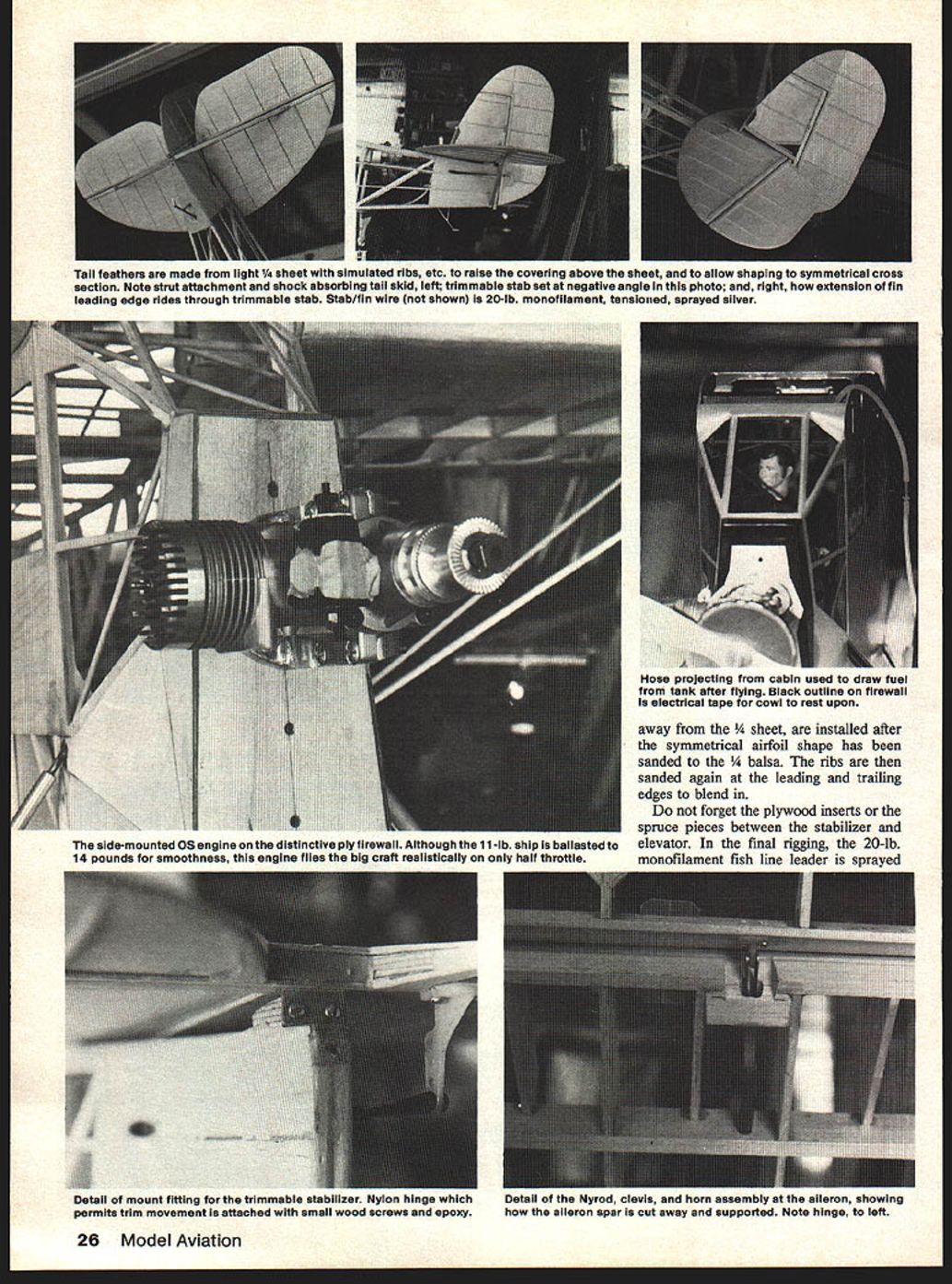
These are cut from very light 1/4" balsa sheet and are explained on the drawing. The simulated ribs and other 1/16" parts that raise the covering away from the 1/4" sheet are installed after the symmetrical airfoil shape has been sanded into the 1/4" balsa. The ribs are then sanded again at the leading and trailing edges to blend in.
Do not forget the plywood inserts or the spruce pieces between the stabilizer and elevator. In the final rigging, the 20‑lb. monofilament fish line leader is sprayed silver and run from the stabilizer on one side through the rudder and through the stabilizer on the other side. Both ends are then wrapped around strut screws: tighten one strut screw, pull the monofilament line tight, then tighten the other.
Wings
The airfoil on the model is the Göttingen 387, with the slight undercamber left out to give it a flat bottom. This undercamber is so slight that it is barely perceptible and has little if any effect on the flight of the model.
The wings are built in two separate panels for transportation reasons. After all ribs, spars, leading edge, trailing edge and aileron spars are cut out and machined, assemble the left‑hand panel first on the drawing over waxed paper. The aileron spars are left in one piece during construction and, because they are made from medium balsa, they are formed later at the tips with medium sandpaper glued to a fairly large block, along with the tips.
The hard balsa tip pieces are epoxied together on a flat surface and left to dry. Later they are shimmed up and fitted to spar ends, trailing and leading edges, and epoxied on. The root ribs are attached using the dihedral braces shown. Add the top 1/16" leading edge along with 1/16" balsa gas tank backing. Add the 1/64" balsa bottom leading edge back to the front spar. Use baby oil to make the wing plan transparent so the right‑hand wing panel can be assembled over the back side of the plan.
With both wing panels completely sanded and shaped, cut out the ailerons. Note that the aileron gap widens towards the tip when sanding—this is as it was on the real aircraft. Make the necessary blocks and notches to actuate the ailerons; Nyrod housings are epoxied in place in each panel. Make the wing strut .031" galvanized steel fittings, but do not attach them to the wing yet. The spar root ends are cut as shown. Holes for rubber hooks are drilled and blind nuts epoxied in.
Wing and Strut Rigging
The struts need no special explanation. Once they are made, connect wings to fuselage with rubber bands between hooks. Lay fuselage and wings upside down on a flat surface. Make a cardboard template to check the 1‑1/2° scale dihedral between fuselage sides and the wing spars on the bottom. Block up the whole ship underneath so that the dihedral is correct and there is about 2° of washout at the wing tips. Attach the bottom strut hooks to the fuselage strut fittings and locate the wing strut fittings on the spars. Attach with bolts as shown.
Covering
The sanding of high points and very careful checking of all points of contact between framework and covering can make the difference between first and last place at a contest. The added time required is well worth it.
My Fairchild is covered with flat aircraft aluminum MonoKote. This covering makes a very realistic finish on any model but is much harder to use than regular MonoKote. In fact, Sid Axelrod of Top‑Flite said they had stopped making it. But the dull surface of this covering, and the fact of not having to paint it, has much appeal. Anyone dedicated to making this scale model won't object to silk and dope, etc.
Flying
I first flew my FC‑2 very early one Sunday morning with our club's president, Gary Brown, handy with a camera. After several takeoff starts for the camera with the tail in the air, but closing the throttle just after being airborne to land and taxi back, I finally had confidence and let it take off for a trip around the pattern. As soon as it was airborne, I found that the stabilizer leading edge had to be full up with full power, and I pushed the lever on the transmitter to this position.
As the model climbed out and after its first turn, I throttled back to about 1/2 power. After the second turn into the downwind leg I found that it would cruise very well at 1/4 throttle. Approaching base leg, I closed the throttle and the nose dipped as on a real ship. At this point I trimmed the stabilizer for glide and it settled into a very nice gliding attitude as I turned into final. The very first landing was a perfect three‑pointer.
Since then I have flown the model many times and made numerous takeoffs and landings. Turns are accomplished with no rudder, and when trimmed, it will fly hands off. No wonder those old‑time pilots thought so much of this design! The model does not seem to have any bad habits, and flown with 1/2 throttle and full up trim on the stabilizer leading edge, it is very hard to stall. When it finally stalls, it only slightly dips its nose to resume straight flight. It does not fall off on one wing, probably because of the tip washout.
While at the beginning it was my intention to have the model wings fold as on the real aircraft, I decided against it because of the complications and time involved. This could be done—and should if built to AMA scale. It would necessitate a different strut attachment at the fuselage, hinging up of the inner rear of the wing and hinging also of the rear spar at the fuselage, etc.
The model was flown in the 23rd annual contest of the Aeroguidance Society of Endicott, N.Y. on July 8–9, 1978. In static judging it tied for first place. I had to abort the second flight of the first day because in building I had forgotten to install the "J" bolts shown on the drawing of the main landing gear strut. One side tore out on the first flight after a real hard landing, because of gusty winds and not‑too‑good piloting. After repairing it as best I could, I tore both sides loose the next day and spent considerable time the next week repairing it, this time with the "J" bolts in place.
The next week, while flying it at the Syracuse Aero Radio Club contest, it placed well in static, but that day the FC‑2 was heavily damaged in a low, downwind fly‑by for the judges. The resulting stall was no doubt caused by a sudden gust from behind. It was that sort of day. I guess I am lucky to be around—I used to fly the big ones!
The model's scale is quite accurate, being enlarged with proportional dividers from my drawing of the real aircraft, which has Fairchild‑Republic's historian and archivist Theron Rinehart's approval in a statement on Fairchild‑Republic stationery. The drawing, photos, the statement, etc., can be obtained from me for proof of scale.
The Fairchild FC‑2 is truly a beautiful flying model and very easy to fly. The crash was not the fault of the design. It simply fell to the ground with no airspeed. It is now rebuilt.
I would like to take this opportunity to thank Connie Moynihan, Gary Brown, our daughter Barb, John and Jerry Byrnes, and my old friend Ken Little for the wonderful photography. Also Herb Harcom of Buzzards Roost, Oklahoma—without his help, photos and knowledge of the FC‑2, and the restoration now in the E.A.A. Museum, this project would not have been possible.
Transcribed from original scans by AI. Minor OCR errors may remain.

