
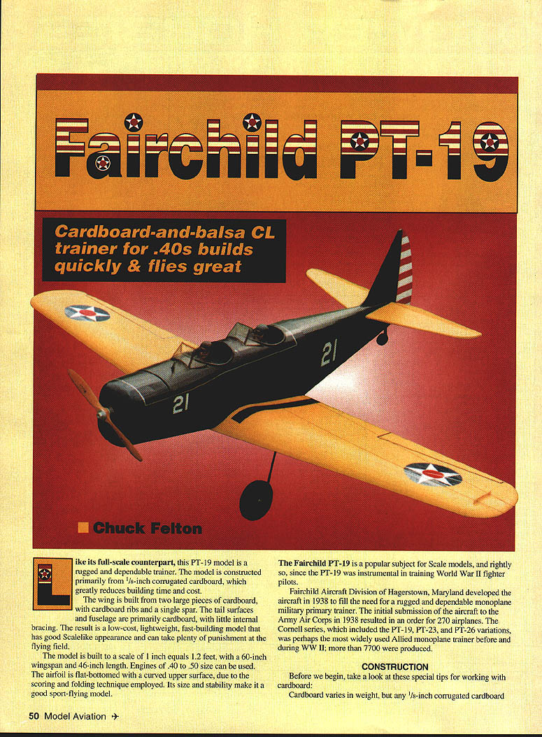
Fairchild PT-19
Cardboard-and-balsa CL trainer for .40s builds quickly & flies great
Chuck Felton
Like its full-scale counterpart, this PT-19 model is a rugged and dependable trainer. The model is constructed primarily from 1/8-inch corrugated cardboard, which greatly reduces building time and cost.
The wing is built from two large pieces of cardboard, with cardboard ribs and a single spar. The tail surfaces and fuselage are primarily cardboard, with little internal bracing. The result is a low-cost, lightweight, fast-building model that has a good scalelike appearance and can take plenty of punishment at the flying field.
The model is built to a scale of 1 inch = 1.2 feet, with a 60-inch wingspan and a 46-inch length. Engines of .40 to .50 size can be used. The airfoil is flat-bottomed with a curved upper surface, achieved by a scoring-and-folding technique. Its size and stability make it a good sport-flying model.
The Fairchild PT-19 is a popular subject for scale models, and rightly so. The PT-19 was instrumental in training World War II fighter pilots.
Fairchild Aircraft Division of Hagerstown, Maryland developed the aircraft in 1938 to fill the need for a rugged and dependable monoplane primary trainer. The initial submission to the Army Air Corps in 1938 resulted in an order for 270 airplanes. The Cornell series, which included the PT-19, PT-23, and PT-26 variations, was perhaps the most widely used Allied monoplane trainer before and during WWII; more than 7,700 were produced.
CONSTRUCTION
Tips for working with cardboard
- Any 1/8-inch corrugated cardboard will work. Sources include box manufacturers and local shopping centers. Look for cardboard with the brown paper side inside and the white finished paper outside; placing the white paper outside on the model results in a smoother finish and neater appearance.
- Use water-based glue such as white glue or Titebond. Contact cement is not recommended since parts cannot be shifted after gluing.
- Score fold lines using a screening tool (available at hardware stores) — a handle with a 1/2-inch-radius wheel. Run it along a straightedge on the fold line.
- Waterproof raw cardboard before cutting: mix 25% clear polyurethane and 75% paint thinner (inexpensive hardware-store varieties are fine). Brush the mixture liberally onto the cardboard sheet and allow it to dry 48 hours. It adds negligible weight and renders the cardboard waterproof; it will cut sharply and cleanly.
- Cardboard provides a solid surface with no open areas to cover. Nonporous surfaces are the easiest finishing method. Give two coats of clear dope, sanding lightly between coats with #400 sandpaper, followed by three coats of color dope.
- A variety of coverings (Solarfilm, MonoKote, vinyl, or paper) may be used; best bonding is achieved by pre-doping surfaces before applying these materials.
- Cover seams, joints, and exposed edges with strips of gummed paper tape. Obtain a one-inch-wide roll at a stationery store; cut thin strips to length, dip in water, and smooth over seams.
- Cut out cardboard and wood parts using the template outlines; note the direction of the corrugations. Score and fold cardboard parts as indicated on the plans.
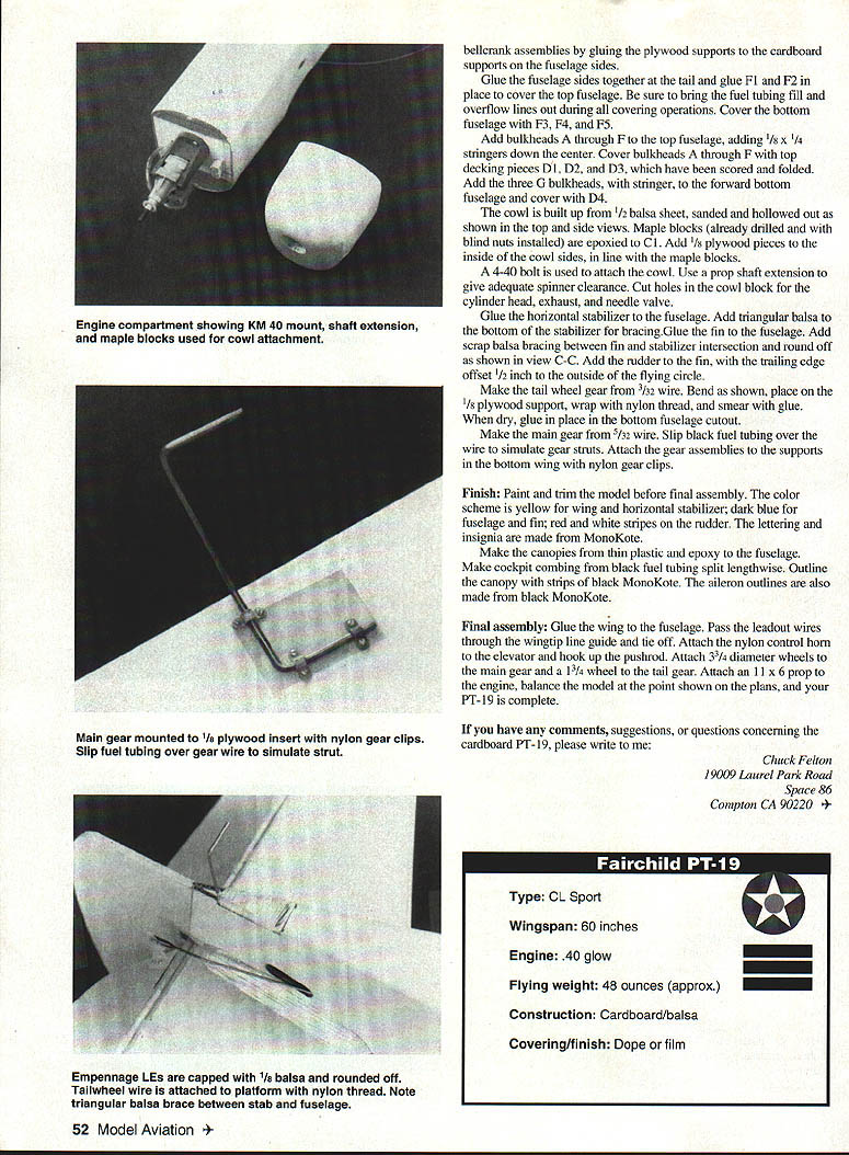
Empennage
- The fin, rudder, stabilizer, and elevator are made from two pieces of 1/8-inch cardboard laminated cross-grain to give 1/4-inch surfaces.
- Add a 1/8 x 1/4-inch balsa strip to the fin leading edge and round off.
- Add 1/8 x 1/4-inch balsa to the stabilizer leading and trailing edges and round off.
- Glue elevators to a 1/4-inch dowel. Add 1/8 x 1/4-inch balsa to the remainder of the elevator leading edge and round off.
- Seal raw edges with gummed paper tape.
- Hinge elevators and stabilizer with cloth hinges in four places.
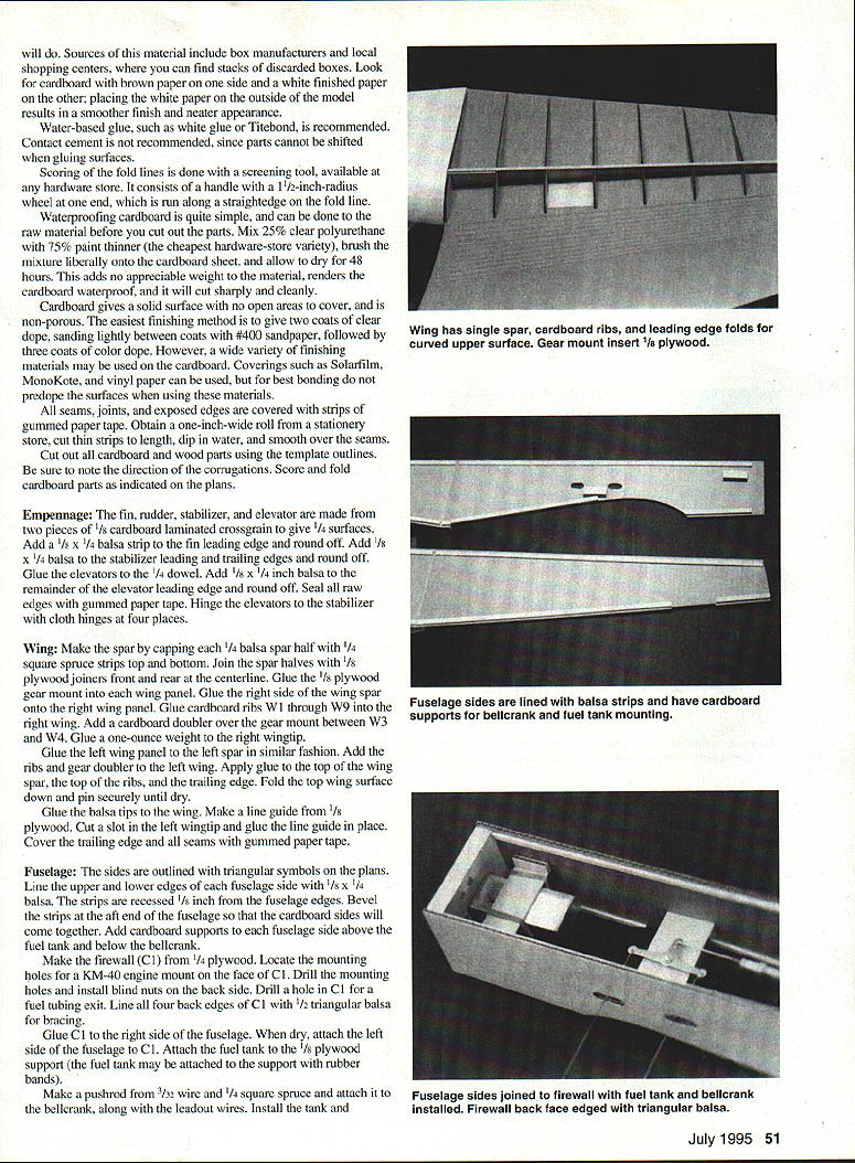
Wing
- Make spar capping from 1/4-inch balsa. Use 1/4-inch square spruce strips for the top and bottom of the spar halves.
- Join spar halves with 1/8-inch plywood joiners front and rear on the centerline.
- Glue a 1/8-inch plywood gear mount to the wing panel.
- Glue the right wing spar onto the right wing panel. Glue cardboard ribs W1 through W9 on the right wing. Add a cardboard doubler over the gear mount between W3 and W4. Glue a one-ounce weight into the right wingtip.
- Glue the left wing panel to the left spar in similar fashion. Add ribs and gear doubler to the left wing.
- Apply glue to the top wing spar, top ribs, and trailing edge. Fold the top wing surface down and pin securely until dry.
- Glue balsa tips to the wing.
- Make the line guide from 1/8-inch plywood. Cut a slot in the left wingtip and glue the line guide in place.
- Cover trailing-edge seams with gummed paper tape.
Fuselage
- Fuselage sides are outlined with triangular symbols on the plans. Line the upper and lower edges of the fuselage sides with 1/8 x 1/4-inch balsa strips recessed 1/8 inch into the fuselage edges. Bevel the strips at the aft end so the fuselage cardboard sides will come together.
- Add cardboard supports to the fuselage side above the fuel tank.
- Make the firewall (C1) from 1/4-inch plywood. Locate the mounting holes for a KM-40 engine mount on the face of C1. Drill the mounting holes and install blind nuts on the back side. Drill a hole in C1 for a fuel-tubing exit. Line all four back edges of C1 with 1/2-inch triangular balsa for bracing.
- Glue C1 to the right side of the fuselage. When dry, attach the left side of the fuselage to C1.
- Attach the fuel tank to the 1/8-inch plywood support (the fuel tank may be attached to the support with rubber bands).
- Make a pushrod from 3/32-inch wire and 1/4-inch square spruce and attach it to the bellcrank, along with the leadout wires.
- Install the tank and bellcrank assemblies by gluing the plywood supports to the cardboard supports on the fuselage sides.
- Glue the fuselage sides together at the tail and glue F1 and F2 in place to cover the top fuselage. Be sure to bring the fuel tubing fill and overflow lines out during all covering operations. Cover the bottom fuselage with F3, F4, and F5.
- Add bulkheads A through F to the top fuselage, adding 1/8 x 1/4-inch stringers down the center. Cover bulkheads A through F with top decking pieces D1, D2, and D3, which have been scored and folded.
- Add the three G bulkheads, with stringer, to the forward bottom fuselage and cover with D4.
Cowl and engine installation
- The cowl is built up from 1/2-inch balsa sheet, sanded and hollowed out as shown in the plans.
- Maple blocks (already drilled and with blind nuts installed) are epoxied to C1. Add 1/8-inch plywood pieces to the inside of the cowl sides, in line with the maple blocks.
- A 4-40 bolt is used to attach the cowl. Use a prop-shaft extension to give adequate spinner clearance.
- Cut holes in the cowl block for the cylinder head, exhaust, and needle valve.
Tailwheel and main gear
- Glue the horizontal stabilizer to the fuselage. Add triangular balsa to the bottom of the stabilizer for bracing. Glue the fin to the fuselage. Add scrap balsa bracing between the fin and stabilizer intersection and round off as shown in view C-C.
- Add the rudder to the fin, with the trailing edge offset 1/2 inch to the outside of the flying circle.
- Make the tailwheel gear from 3/32-inch wire. Bend as shown, place on the 1/8-inch plywood support, wrap with nylon thread, and smear with glue. When dry, glue in place in the bottom fuselage cutout.
- Make the main gear from 5/32-inch wire. Slip black fuel tubing over the wire to simulate gear struts. Attach the gear assemblies to the supports in the bottom wing with nylon gear clips.
Finish
- Paint and trim the model before final assembly.
- Recommended color scheme: yellow for wing and horizontal stabilizer; dark blue for fuselage and fin; red and white stripes on the rudder.
- Lettering and insignia are made from MonoKote.
- Make the canopies from thin plastic and epoxy them to the fuselage.
- Make cockpit combing from black fuel tubing split lengthwise. Outline the canopy with strips of black MonoKote. The aileron outlines are also made from black MonoKote.
Final assembly
- Glue the wing to the fuselage.
- Pass the leadout wires through the wingtip line guide and tie off.
- Attach the nylon control horn to the elevator and hook up the pushrod.
- Attach 3-3/4-inch-diameter wheels to the main gear and a 1-3/4-inch wheel to the tail gear.
- Attach an 11 x 6 prop to the engine.
- Balance the model at the point shown on the plans.
If you have any comments, suggestions, or questions concerning the cardboard PT-19, please write to:
Chuck Felton 19009 Laurel Park Road Space 86 Compton, CA 90220
Specifications
- Type: CL Sport
- Wingspan: 60 inches
- Length: 46 inches
- Engine: .40 glow (recommended .40 to .50 size)
- Flying weight: approx. 48 ounces
- Construction: Cardboard/balsa
- Covering/finish: Dope or film (e.g., MonoKote)
Transcribed from original scans by AI. Minor OCR errors may remain.

