
Frank Roales
Fake Ford
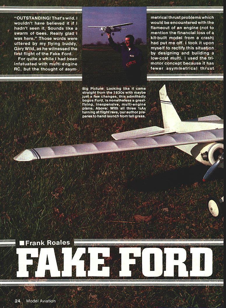
"OUTSTANDING! That's wild. I wouldn't have believed it if I hadn't seen it. Sounds like a swarm of bees. Really glad I was here." Those words were uttered by my flying buddy, Gary Wild, as he witnessed the first flight of the Fake Ford.
For quite a while I had been infatuated with multi-engine RC, but the thought of asymmetrical thrust problems that would be encountered with the flameout of an engine (not to mention the financial loss of a kit-built model from a crash) had put me off. I took it upon myself to rectify this situation by designing and building a low-cost multi. I used the tri-motor concept because it has fewer asymmetrical thrust problems with an engine loss. Since the most recognizable tri-motor plane was the Ford, I dubbed mine the quasi-scale 1/2A Fake Ford.
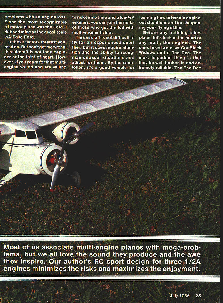
If these factors interest you, read on. But don't get me wrong; this aircraft is not for a beginner or the faint of heart. However, if you yearn for that multi-engine sound and are willing to risk some time and a few 1/2A engines, you can join the ranks of those who get thrilled with multi-engine flying.
This aircraft is not difficult to fly for an experienced sport flier, but it does require attention and the ability to recognize unusual situations and adjust for them. By the same token, it's a good vehicle for learning how to handle engine-out situations and for sharpening your flying skills.
Engines and Engine Preparation
The engines I used were two Cox Black Widows and a Tee Dee. The most important thing is that they be well broken in and extremely reliable.
Black Widow modifications (for best accessibility and performance)
- Disassemble the rear tank.
- Move the fuel pickup tube in the rear plate from the side to the bottom. This modification should be done only on the engine to be run backward.
- Lap both tank surfaces for a good fit.
- Rotate the tank center section so that the cylinder and needle valve are to the outside when the fill tube is up. Do one tank with the cylinder and needle valve on the left and the other with them on the right so that, when mounted, both engines have cylinders and needle valves outboard.
- Remove the needle valve spring and replace it with a short piece of small fuel line over the entire lower part of the needle valve and tank top. This will keep the needle from turning unintentionally and also keep air from bleeding into the fuel supply, which can cause erratic runs.
Fuel and props
- Use about 20% nitro fuel. The little engines don't like regular RC sport fuel; however, since fuel consumption is low you won't have to spend much on high-nitro fuel.
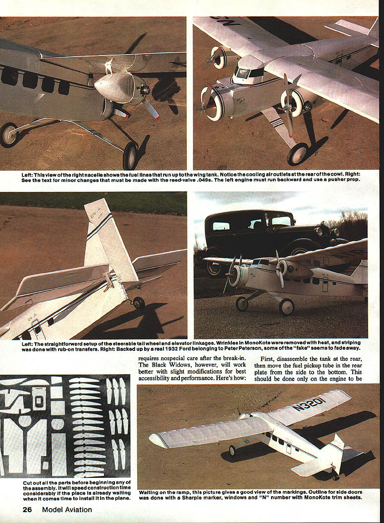
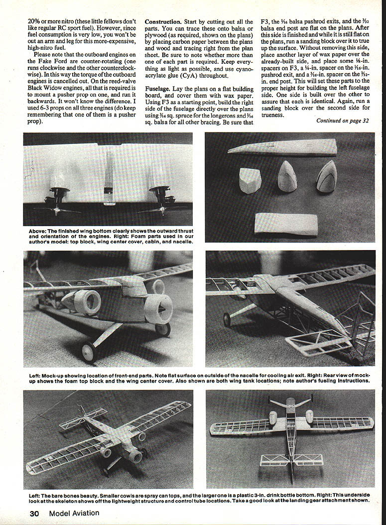
- The outboard engines on the Fake Ford are counter-rotating — one runs clockwise, the other counterclockwise — so the torque from the outboards cancels out. Reed-valve Black Widow engines require mounting the pusher prop to run backwards; you won't notice the difference in operation.
- I used 6x3 props on the three engines — remember to use a pusher prop where required.
Note: Be sure the engines are reliable and well broken in before installation.
Construction
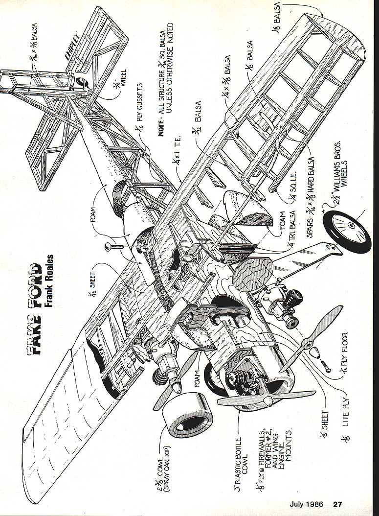
Start by cutting out all the parts. You can trace parts onto balsa or plywood by placing carbon paper between the plans and the wood and tracing directly from the plan sheet. Be sure to note whether a part is right or left and whether more than one is required. Keep everything as light as possible and use cyanoacrylate glue (CyA) throughout.
Fuselage
- Lay the plans flat on the building board and cover them with wax paper.
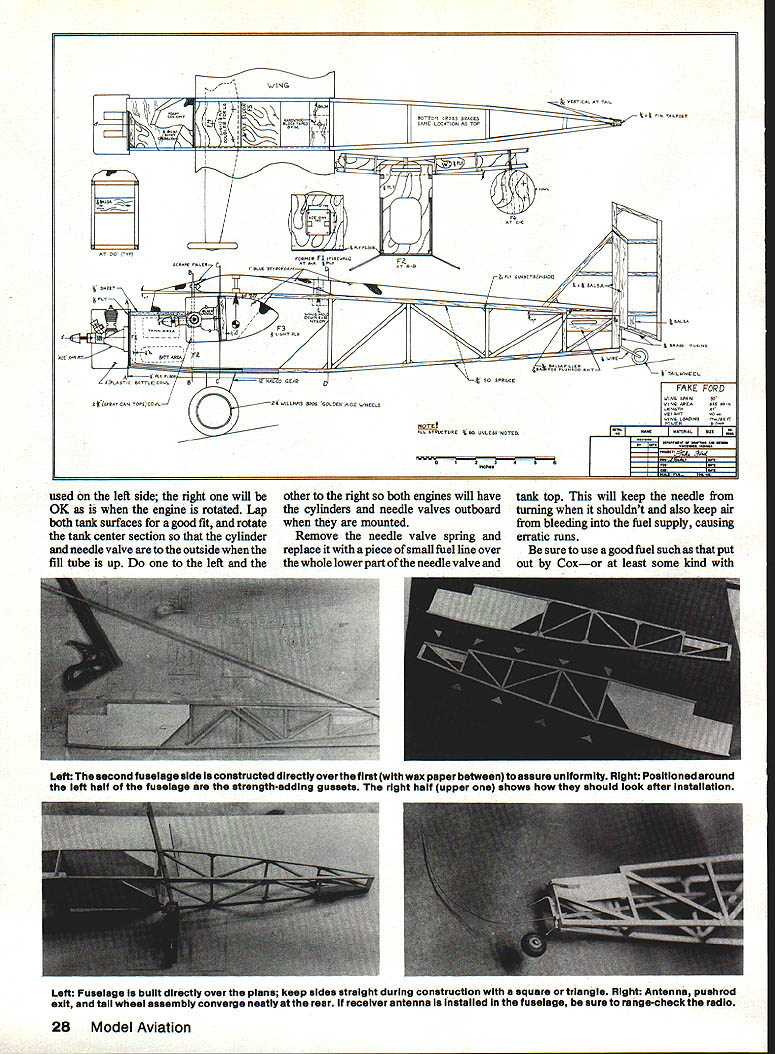
- Using F3 as a starting point, build the right side of the fuselage directly over the plans using 3/16-in. square spruce for the longerons and 3/16-in. square balsa for other bracing. Ensure F3, the 1/8-in. balsa pushrod exits, and the 3/16-in. balsa end post are flat on the plans.
- After the side is finished and still flat on the plans, run a sanding block over it to true the surface. Without removing this side, place another layer of wax paper over it, and use spacers on F3 and the pushrod/end-post locations to set proper heights. Build the second fuselage side directly over the first (wax paper between) to assure uniformity. Sand the second side for trueness.
- Remove the sides from the board. With flush sides down, cut gussets from 1/4-in. ply for the rear-side joints (cut 3/4-in. squares of 1/4-in. ply diagonally) and glue them inside all joints from F3 to the rear. Do not omit these gussets — they add little weight but greatly increase strength and rigidity.
- Mark and drill F1 per the plans for your engine mount. Glue F1 and F2 in place using 1/4-in. triangular stock as shown; use a square to keep them true. Add the other fuselage side and check for squareness.
- Finish the fuselage assembly by building over the top view and adding cross braces as required. Note the cutout at the rear for the fin post. Add the landing gear doubler, 1/8-in. top block, wing hold-down block, and outer tubes for the rear pushrods and antenna exit.
- You may wish to install the main engine tank before gluing the 1/16-in. ply fuselage floor in place. The prototype used an R1 Sullivan tank siliconed to the fuselage side and top block. Drill the fuselage floor and gear doubler for your landing gear, and install blind nuts.
- Cut out the rear fuselage top and cabin from 1-in. foam as shown. The cabin is laminated from two pieces. I used blue Styrofoam, cut with an X-Acto knife and coping saw, then shaped with a sanding block. Fill dents with gap spackling compound (it doesn't attack the foam). Use a low-temperature iron when covering foam parts (Ekonokote, Solarfilm, etc.). Use white glue to attach Styrofoam; cover the rest of the fuselage with your preferred iron-on covering (I used Super MonoKote).
Install the antenna pushrod exit and the tail-wheel assembly so the pushrods converge neatly at the rear. Install the receiver antenna inside the fuselage and be sure to range-check the radio.
Tail surfaces
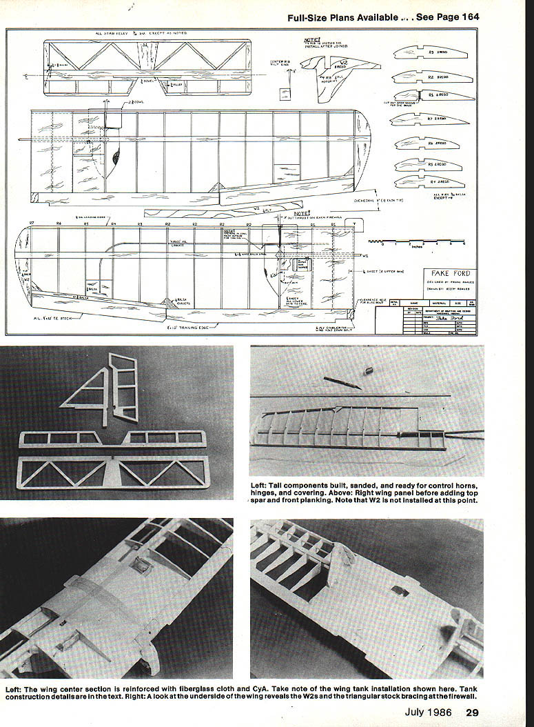
- Build the fin and rudder directly over the plans using 1/16-in. sq. and 3/16 x 3/8-in. balsa as specified. Note the fin post extends down into the fuselage; choose light, firm wood for the tail assembly.
- Build the stabilizer and elevator in the same manner. Don't forget the cutout at the rear center of the stab for the fin post.
- Sand each part flat, round all edges, cover, hinge, and add control horns before assembly.
Wing
- The wing is built directly over the plans. Pin down the 1/16 x 3/8-in. hard balsa spar.
- Add the 3/32-in. leading edge and trailing edge sheeting. Install rib W2 at the center and pin the rest of the ribs in place. Install the top spar, then add top planking and tip blocks. Add shear webs as shown on the plans.
- Install the lower 1/16-in. balsa sheet to W2 and place the R1 ribs on top of this sheet, keeping all ribs vertical except the center rib (use the rib tilt gauge on the plans for positioning).
- Add the 1/4-in. sq. hard balsa leading edge, the 1/4 x 1-in. trailing edge, and the 1/4 x 1/2-in. balsa aileron. Cut out the spar and wing tip. Add the 1/8-in. plywood dihedral brace and the 1/8-in. triangular stock at the inside of W2, and glue in the upper spar.
- Build the other panel up to the dihedral brace. Assemble the two wing halves by raising the outer end to the dihedral angle to yield 3 in. dihedral at the wing tip. Keep the joint square and flat; glue them together.
- Add the 1/4-in. balsa triangle at W2 and the top spar to the final panel. Add aileron linkage, sheet the wing upper center, and wrap the center joint once with 1-in.-wide fiberglass cloth attached with CyA. Add the wing hold-down doubler and locating tongue using F2's cutout to obtain the proper incidence.
- Block-sand the entire wing smooth using a long sanding block.
Engine mount and tanks in the wing
- Add the W2 engine mount ribs, ensuring the lower part is 90° to the bottom sheeting. Add 1/4-in. triangular pieces to the outer rib dihedral brace joint and inner bottom sheeting.
- Locate holes in the outer firewalls for your engines, drill them, and install blind nuts. Mount engines on W2s with 3° of out-thrust on each; use 1/4-in. triangle stock sanded to the correct angle to reinforce both sides of W2.
- Mount auxiliary wing tanks for the outboard engines as shown. The tanks are #5 Perfect rectangles modified by removing the pickup from the center top and relocating it to the outboard end so it will come through the lower 1/8-in. sheet just inside W2. Run a fuel line from the tank to the engine. Hold tanks in place with silicone caulk and a small sheet of 1/16-in. balsa over them.
- Fine-sand the wing, hinge and cover the ailerons, and add control horns.
Nacelles
- Nacelles are made from foam, sanded to shape, covered with a low-temperature Mylar film, and glued to the rear of the firewalls (W2) with white glue.
Final assembly
- Glue on the tail surfaces with the stab/elevator flat and the rudder/fin perpendicular.
- Make and attach the tail wheel as shown on the plans; let the upper part that goes to the tube on the rudder remain free to prevent binding.
- Place the wing on the fuselage and check incidence and squareness.
- Make wing seals with silicone caulk: lay a small bead on the upper fuselage, wrap the contact area of the wing with wax paper, bring the wing into alignment, and let the silicone dry in position to create a perfect fit.
- Add main gear wires using small hardwood blocks. On the prototype the outboard mounts used spray-can tops and the center one used the bottom of a 3-in.-dia. plastic bottle.
- Mount the radio gear and shift it forward or backward to obtain the proper center of gravity. If necessary, add weight to achieve correct balance; this shouldn't be necessary if wood selection and construction were careful.
- Do not attempt to fly the model until it balances in the designated position.
Flying
Check all controls to ensure they operate in the correct direction, move freely, and have the proper throws.
Recommended control throws for first flights:
- Aileron and elevator: 3/8 in. up and approximately the same down.
- Rudder: 1 in. each side of center.
- Be sure you have maximum trim available, especially for the rudder.
Fuel filling procedure for the outboard tanks:
- Place the tube from the wing tank to the engine fill tube and an extension on the engine overflow tubes.
- Fill through the wing tank until fuel comes out the engine overflow.
- Plug the engine overflow and finish filling the wing tank normally. The wing tank can then be topped off directly.
Engine start and launch procedure:
- Start each engine, allow it to warm up, and set the needle valve.
- Shut each down and top off the tank.
- Start the outboard engines first; when both are running, top them off.
- Start the center engine and launch the model. Hand-launching is recommended for the first flights.
If this starting procedure is used, the outboard engines will die first and nearly at the same time, leaving the center engine running for more positive landing control.
Engine-out handling
- If you lose an engine, determine which one it is, and use rudder for trim corrections.
- Do not attempt to turn into the dead engine; make all turns very shallow and away from the dead engine.
- This airplane flies well on any two engines, but do not get too far from the landing strip if you have just one engine running. If an outboard engine quits it will stretch the glide; performance with only the center engine is only slightly better.
- When one engine quits, think rudder and make coordinated, shallow corrections.
Happy flying! I think you will enjoy the sound of three unsynchronized engines in full flight. If you have any comments or questions, please write me (enclosing a pre-addressed, stamped reply envelope):
Frank Roales R.R. #3 Box 49B Vincennes, IN 47591
Transcribed from original scans by AI. Minor OCR errors may remain.

