
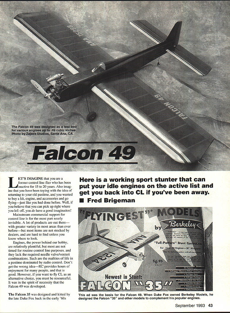
Falcon 49
Here is a working sport stunter that can put your idle engines on the active list and get you back into CL if you've been away.
- Fred Brigeman
Let's imagine that you are a former control-line flier who has been inactive for 15 to 20 years. Also imagine that you have been toying with the idea of returning to your old pastime and wanted to buy a kit, engine, and accessories and go flying—just like you had done before. Well, if you believe that you can pick up right where you left off, you do have a good imagination.
Mainstream commercial support for control line is, for the most part, nearly invisible. A lot of products are out there—with greater variety in some areas than ever before—but most items are not stocked by dealers and are hard to find unless you know where to look.
Engines, the power behind our hobby, are relatively plentiful, but most are not timed or configured for routine control-line purposes and lack the required needle-valve/venturi combinations. Such are the realities of life in a pastime dominated by radio control. Don't get the wrong idea—R/C provides hours of enjoyment for many people, and that is good. However, if you want to fly control line as an alternative, you must be resourceful. It was in that spirit of necessity that the Falcon 49 was developed.
The Falcon 35 was designed and kitted by the late Duke Fox in the early '60s through Berkeley Models. Though particularly attractive, Duke claimed the airplane was designed as a flying testbed for Fox engines of the day. As his first sport-stunt project beyond Ringmaster/Rite Streak–type models, the contest-plane–sized Falcon 35 was ticketed at the advanced level. Stunt models have always held a special place in many memories. After a dormant period I yearned to build another Falcon 35; alas, phone calls to Fox revealed no kits or plans available—the factory had been destroyed and existing copies of the airplane were gone.
Viewing this temporary setback, I tried drawing reproduction plans using old snapshots and available pictures. Clear side views were enlarged on the photocopier, but the results were disappointing—an unacceptable loss of detail. I realized a true duplicate wasn't really what I needed. I wanted a more obvious, logical approach: design an airframe that would accept today's as well as yesterday's engines. I decided the body should resemble the old pictures but also be able to try different engines.
With that revised goal, I tried to think like Duke Fox and set out to design a non-flapped airplane that was especially attractive and capable of flying reasonably well. I wanted something able to perform general maneuvers with a variety of engines up to .49 cubic inch; that would satisfy the dream.
I researched proven airfoil/moment combinations and articles published over the years. After borrowing some ideas, I sat down at the draftsman's CAD machine to transfer the Falcon 49 concept onto paper. With a picture of the original Falcon 35 and rough sketches of the new model before us, we arrived at a compromise that turned out to be a modern, utilitarian design with old-time style outside and up-to-date features inside.
Not knowing exactly what to expect, I used those early CAD drawings to cut parts and build the model. I was pleasantly surprised to find I had constructed a heavy-duty flying test bed that can accept an engine as large as a .60 but is kept busy trying numerous .40-, .46- and .49-sized power plants.
The Falcon 49 is stable and capable of carrying fuel loads to match the engine being used. It's an easy, straightforward project that utilizes both old and new technologies. If building an airplane that can test-run most of your favorite old engines or some of today's newer, RC-based power plants sounds good to you, then let's get started.
Materials Selection
All materials used to build the original Falcon 49 were purchased from hobby shops near my home. If you are lucky enough to have a local hobby shop, use and support it—there is no substitute for picking out your own wood and other items.
Many good dealers will gladly order control-line items for you if they can locate a supply source. This special-interest service is frequently missing at shop-by-mail, R/C-oriented discount houses. If you don't have a dealer near you, order a catalog from Sig Manufacturing in Monezuma, Iowa. As a major supporter of control-line activity, Sig is a reliable source for everything needed to build the Falcon 49.
Be reasonably sensitive to weights when selecting your balsa. Heavy, dense wood is something every modeler has lying around; I mistakenly used some of my heftier stock on this project thinking it "wouldn't be wasted." Trust me—unless you want to hope your lines will hold a really heavy airplane through a six- to eight-minute flight, pick the lightest, best balsa you can find. A lighter airframe performs better and will permit mounting a heavier engine and balancing weights while retaining acceptable flight characteristics.
The original model used four-inch-wide stock for the leading-edge planking to retain a true airfoil shape from the front radius to the high point (spar area) of the wing. The same result can be achieved by splicing more economical pieces of three-inch-wide stock with one-inch strips to make wider planking. Be sure the plank edges are trued with a straightedge to assure a good fit.
The same procedure can be used with the 1/8" fuselage sides, which were also cut from four-inch-wide stock on the original version. If you splice balsa planks, be certain the cement used is a type that can be sanded easily.
Speaking of cements, longtime builders will remember the traditional solvent-based model cements once used almost exclusively. These days there are other choices:
- Quick-bonding cyanoacrylates (CyA)
- Water-based aliphatic resins (carpenter's glues)
- Epoxies
All of the adhesives mentioned are currently available and can be used to build the Falcon. If you are a traditionalist and want to use Ambroid, Sig-Ment, Duco, or Testors for the fun of it, feel free to do so. These cements are strong and reliable.
For safety, be aware that solvent model cements, some CyA formulations, and even some epoxies can give off powerful fumes that may be harmful. Provide good ventilation and take appropriate precautions when and where you build.
Construction
Many designers will tell you to precut all parts needed to "kit" a model; however, some builders find this process dull and tedious. As a compromise, cut parts for major subassemblies as needed. Whatever method you use, precaution usually starts with the wing.
Some modelers have never attempted to scratch-build because they think producing a wing might be too difficult. It's only a matter of coming up with a good set of parts, so let's cover some details.
Wing Ribs and Templates
Several options can be used to make a stack of identical ribs for a constant-chord wing. A friend fashions a brass template and cuts identical ribs one at a time. Another faster method is to sandwich a stack of balsa blanks between two thin aluminum templates, then use a large sanding block to shape the blanks to their final form.
The plans show templates for both the wood size needed for rib blanks and the rib outlines. Cut the rectangular, dotted outlines from the plans and use rubber cement or spray adhesive to attach them to a piece of rigid material, such as .015" aluminum sheet. The aluminum can be ordered from a hobby source or salvaged from scrap siding.
Trim one rectangular template precisely to the dotted outline with your cutter and rough-trim the other. Using the precision-trimmed rectangular template as a guide, cut twenty 1/16" sheet rib blanks to size.
Drill two 7/64" holes in each of the rectangular templates at the locations shown. Using the precision-cut template as a guide, carefully drill similar holes through all of the blanks, five at a time. Then cut out the actual rib templates by following the rib outlines.
Sandwich 10 rib blanks between metal rib templates and bolt the stack together with firm (but not crushing) pressure. Place large washers between the bolt heads and templates to help spread the load. Rough-carve the excess balsa, then sand the blanks to shape, taking care not to cut excessively at the metal templates.
Clearly mark the top of the rib stack with a felt-tip pen, then disassemble it. Repeat this procedure with the second group of blanks, taking care to align both templates right-side-up exactly as they were placed on the first set. Again, mark the rib tops before you disassemble the stack.
Cut out and paste the finishing rib pattern to a rigid piece of cardboard or plastic, trim to the outline, and cut the shaded spar and leading-edge locations. Use this pattern to mark each rib. Carefully hand-cut and remove the spar/leading-edge locations where required. When finished, you should have a stack of identical ribs—just as you would find in a kit.
Building the Wing — Rod-Type Jig
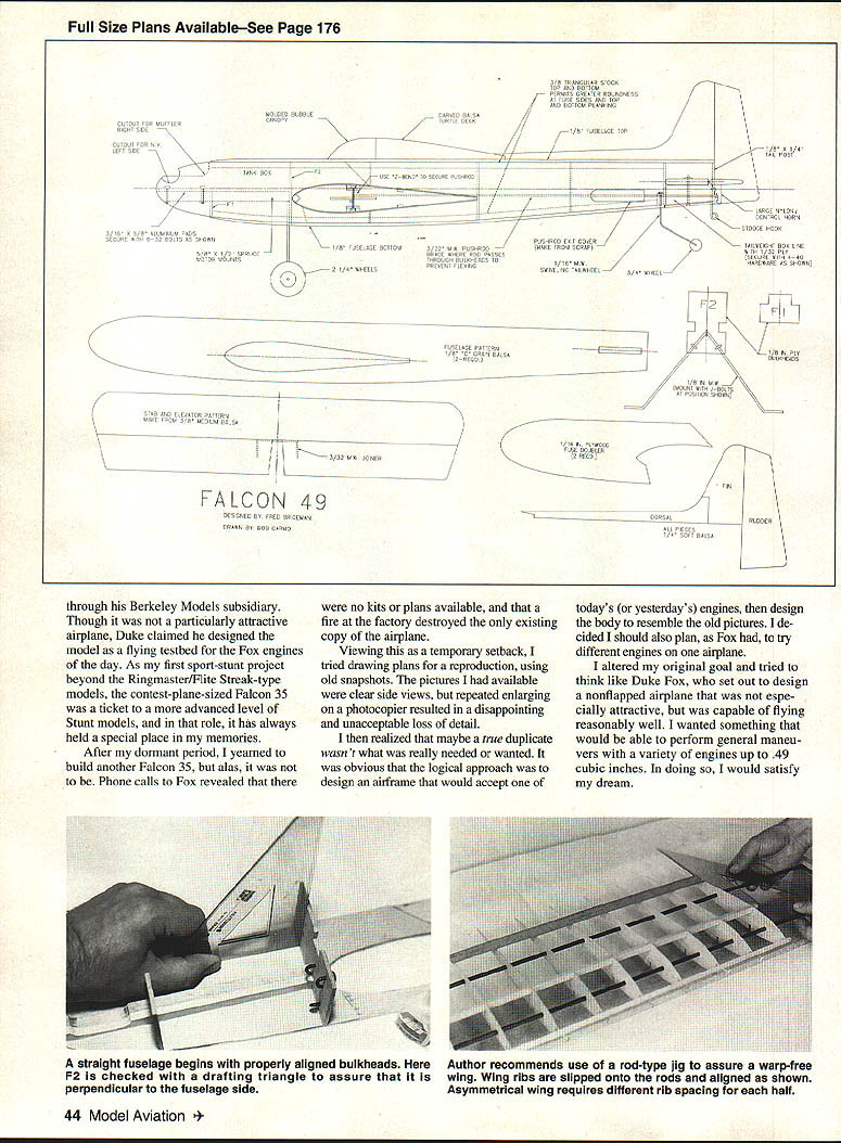
Assemble the wing on a building surface verified as free of twists and warps. The traditional "pin the trailing edge and hold the leading edge and spar" method is acceptable; however, to increase the chances of a warp-free wing, try a rod-type jig.
A steel-rod jig was developed by Al Rabe and discussed by Bob Baron in his Fierce Arrow '68 article (Model Aviation, July 1987). Great Planes' version of this jig can be ordered through your dealer or from Tower Hobbies. It takes some adjustment to adapt to building "on the rods," but once you try it, you'll have trouble going back.
The 1/8" holes you drilled in the rib blanks are now used as locations for the 1/4-inch jig rods. To make the proper-size holes, use a Dremel tool mounted on a drill press fixture and a 1/4" tapered reamer or a similarly controlled method. Keep in mind that the holes must be kept in the same plane and must fit snugly on the rods.
Make sure the index marks you added earlier are facing up, and slip the ribs onto the rods. Space the ribs as shown on the plans and construct the wing framework. Note: because of the size of the jig fixture, you will build the left and right panels independently. The wing is asymmetrical (one panel is slightly longer than the other), so make sure the rib spacing for each panel matches the plans. When each panel is dry, carefully remove the rods using a gentle rotating motion to avoid damaging the structure.
When both panels are complete, trim and sand the center section to be certain all planked portions are parallel and true. Reinforce the center section as shown and reinsert the rods through the central area before removing the panels from the building board. With the rods reinstalled, join the panels together with the center-section top and bottom sheeting in place.
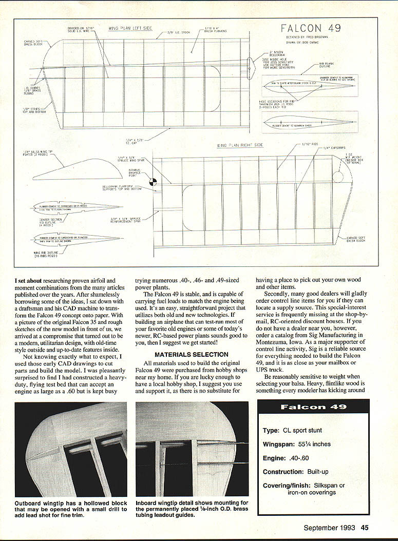
Pin the trailing edge of each panel to your building surface and measure the leading-edge height to ensure both sides are equal. Join the panels at the center section with spruce stringers and balsa splices, and let dry. Remove the pins and rods, then add the bellcrank assembly, the trailing-edge cap, wing tips, tip blocks, and center-section planking. The wing is now solid, straight, and ready for sanding.
(Another, more expensive jig unit called the Adjust-O-Jig allows you to build the wing in one piece and avoid the joining process altogether.)
Fuselage Structure
The Falcon's fuselage is wider and beefier than normal. It’s designed to handle heavy vibration and the stress imposed by varied engine choices. It serves as a joining point for the wing and empennage and houses the mounting platform for the removable engine hardware and tank. For the structure to do its job effectively, pay particular attention to physical strength and proper alignment.
Begin by cutting the fuselage sides from 1/4" x 4" x 36" stock. As mentioned above, you may splice the wood needed from narrower sheets without strength penalty. Similarly, cut doublers from 1/16" birch plywood. Check for fit, trim the doublers where necessary, and cement them in place. I usually use 30-minute epoxy for this job; however, respected builders have used CyA to attach doublers on .60-size models, so the choice is yours. CyA is fast and light, but once it “kicks,” there are no second chances.
Before assembly, be certain the parts match and that you will finish with right and left sides. Cut the 1/8" birch plywood bulkheads. It is here that you'll begin to see how the Falcon differs from other airplanes.
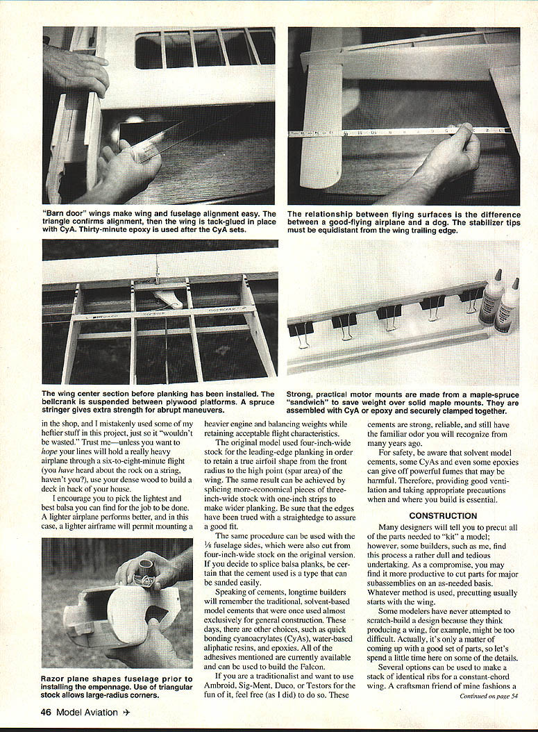
Notice that the motor mounts are larger than normal and are constructed from a hardwood/spruce combination. This increases the attachment area for the cement on the fuselage sides without the weight penalty of mounts made entirely from hardwood.
Make the mounts by cutting 1/4" x 1/2" spruce strips and 3/8" x 1/2" maple motor-mount stock. The objective is a mount 5/8" high and 1/2" wide. The spruce portion is located below the harder maple, which remains on top for strength.
After constructing the motor-mount “sandwich,” cut out the area shown for bolt clearance and prepare to cement the mounts to the fuselage sides. Trace a template of the upper fuselage side and use it to draw layout lines on the doublers to make certain both mounts are identically located and parallel. Use 30-minute epoxy to glue the mounts precisely along the layout lines, then clamp them firmly while the adhesive sets.
Once the epoxy has set, join the fuselage sides. Assemble the fuselage with both sides and the two main front bulkheads upside down, using the flat top area of the fuselage sides as the parallel elements in contact with your building surface.
Some builders use a commercial jig to assure true alignment; however, a reliable method is to draw a centerline on the building board and line it up with centerlines drawn on the two main front bulkheads. Using blocks of balsa pinned to the board and against the outside perimeter of the engine/tank-box area, the fuselage can be kept rigid and straight for the initial cementing. Tack-glue the tail post at this time to ensure both sides are parallel front-to-back. When set, the tail post should be directly over the centerline.
To increase resistance to vibration, tightly fit a piece of 1/16" medium balsa (crosswise grain) between the motor mounts, closing in the area between F1 and F2. This piece acts as a stress web, tank floor, and provides a solid front end that allows this model to handle larger engines.
The remaining formers are cut from sheet balsa set to the proper width at each station, slip-fit in place, then trimmed and sanded to correct height.
Tail Surfaces and Weight Box
The tail surfaces are made from solid wood. Even though extreme light weight is not necessarily the goal for this aircraft, make an effort to find the lightest, straightest stock possible for the empennage. It is interesting to note that most engine/muffler combinations I have tried cause the airplane to either balance right at the point shown on the plans or to be only slightly nose heavy. For your Falcon, don't gamble—make the tail feathers light; you will be able to add balance weight later.
The majority of the fuselage construction is conventional except for the rear of the aircraft. A weight box located under the horizontal stabilizer allows you to adjust the aircraft's balance point for different engines. The box area is lined with 1/32" plywood to help prevent vibration damage from whatever weights you select.
I use 1/2-ounce lead putty slugs, available from R.D. Industries. This product can be molded to shape, doesn't rattle, and is infinitely variable in amount.
A swiveling tail wheel is suggested on this design as well as the provision for a stooge-release ring. Though a full-castering tail wheel might seem to let the airplane turn in, in practice it doesn't affect takeoffs or landings. The freedom of the tail wheel to move in the direction of travel allows you to actually walk the plane back to the launch point from the center of the circle. If you fly from grass, however, this feature is not useful, and a conventional fixed wheel or skid is preferable.
Final Assembly
All subassemblies should now be planed, carved, and sanded to shape as necessary. Fill dings and imperfections with Golberg Model Magic filler or a similar product found at home-improvement stores. The objective is a surface below your finish that is smooth and free from major flaws.
Cut away the bottom of the fuselage in the wing-mounting area as shown on the plans. Carefully insert the wing into its opening to check fit. You may need to trim the fuselage openings slightly so the wing makes the best possible contact with the fuselage sides. Be careful not to cut away too much material. Avoid changing the incidence of the wing or your ability to mount the wing parallel to the fuselage sides.
Fit the stabilizer into its slotted opening and adjust the opening so the stabilizer easily sits parallel to the fuselage.
Check vertical and horizontal alignment with a triangle. I usually check the spar-to-fuselage area and the leading-edge-to-fuselage on both sides of the airplane, then tack the wing to the fuselage with CA once I am absolutely certain the alignment is correct on each side.
Hold the elevator joining wire in place at the rear of the stabilizer slot and slip the wire into position. Secure the joining wire to the stabilizer, then install the hinges and elevators.
Alignment of the wing and stabilizer is next. Measure the distance at the rear of both sides of the stabilizer and the trailing edge of the wing. Sight down the fuselage from front to rear, eyeballing the relationship of the stabilizer to the wing. Once certain the stabilizer is horizontal and vertically aligned (shim as necessary), tack-glue the stabilizer into place and allow it to dry while you monitor the assembly for any sign of twist or droop.
Install the weight box in the tail section and reinstall the under-wing sections of the fuselage that you removed earlier. Reinforce the tail boom and permanently cement the wing and stabilizer in place using a light coat of 30-minute epoxy. Install the fuselage top and bottom planking, carve and finish-sand to final shape. Add the canopy tumbledeck, fin and dorsal assemblies, and the rudder, then allow to dry. You are now ready to finish the Falcon.
Finishing
The wing structure of the Falcon was designed for any of the popular iron-on covering materials. As an appreciator of the old-time, traditional approach, I used silkspan and dope on the original. Either method has advantages and disadvantages, but if you want to update your knowledge and skills, try modern plastics.
In addition to engine testing, this project was an opportunity to experiment with Sig Expoxolite for fillets instead of plastic balsa. I also tried adding a tinting medium to clear dope to provide a vivid base color without the weight of pigmented color coats.
If you are a former CL buff coming back into the hobby, this airplane is an ideal platform to experiment with different or unfamiliar materials. Never be afraid to try something new.
All engines you may want to use can be mounted on the 3/16" x 5/8" aluminum pads shown on the plans. The pads, cut from strips available at any metal supply house, are identically drilled to fit into the same holes on the motor mounts. By using the pads, it's not necessary to repeatedly redrill the mounts themselves when changing power plants.
The tank compartment is large enough for a Sullivan eight-ounce clunk. If you don't have much luck with clunk-type tanks, you may also use a metal tank of standard uniflow construction as a substitute.
Ken Smith of Smith Fuel Tanks designed a special product for this airplane called the Falcon 49 tank. This unit has greater height, width, and volume than typical commercially available varieties. It also comes properly vented for the upright engine configuration of the Falcon 49, and the pickup tube of the Smith tank is located to allow for the additional height of the engine mounting pads.
Once you have added the vinyl lettering (water-transfer decals are rare these days), wheels, and hardware, balance the Falcon at the point shown on the plans. This is a good starting point and where my airplane flew best; however, you may want to eventually move the balance point forward or aft to suit your style. Remember this airplane is not intended to be a giant-killer Precision Aerobatics model, so you may not want to expend great effort on precise trimming. Sufficient attention to basic balance will allow you to gain the greatest utility and pleasure from your model.
Flying
Always pick a calm day, or at worst a day with a light breeze for test flying. Flying an unfamiliar airplane in high winds or gusty conditions is an invitation for disaster.
Try simple maneuvers first; then, if things look okay, consider something more complex, like lazy eights or inverted flight. Be advised that losses of power while inverted are not particularly kind to the head of an upright-mounted engine. To be safe, try your first inverted flights high enough to be able to recover the airplane in case of a flameout. Once you are confident of your model's fuel flow and engine characteristics, routine maneuvers should be no problem.
This article was written with sufficient detail to take almost anyone through the rough spots. For old hands coming back into the fold and trying to catch up with the times, these experiences and building techniques may provide encouragement and new ideas to try. Read articles in our magazines for inspiration and new approaches to routine tasks.
If you have any questions about a design feature not mentioned here, feel free to call me at (714) 667-7178 after 7 p.m. Pacific time; I will be happy to try to answer questions. If you decide to build this airplane, I would be honored to receive a picture of your finished Falcon 49 for my album. Send photos or correspondence to:
Fred Brigeman P.O. Box 1935 Tustin, CA 92681-1935
Transcribed from original scans by AI. Minor OCR errors may remain.

