

FAST BLASTA
Richard Wilkens
THE IDEA THAT I should enter the 1975 U.S. Nats came from Charlie Johnson and Gary Frost, whom I had met at the British Nats in May 1975. I was already booked for a peaceful hitchhike tour of that little old country of yours, so when Charlie suggested that I should visit him in California before the Nats, I boxed five FAI Blastas left over from the British International and headed West. Charlie and Lorna gave plenty of advice on Fast Combat. If it hadn't been for them it would have been doubtful if I could have entered the Nats at all.
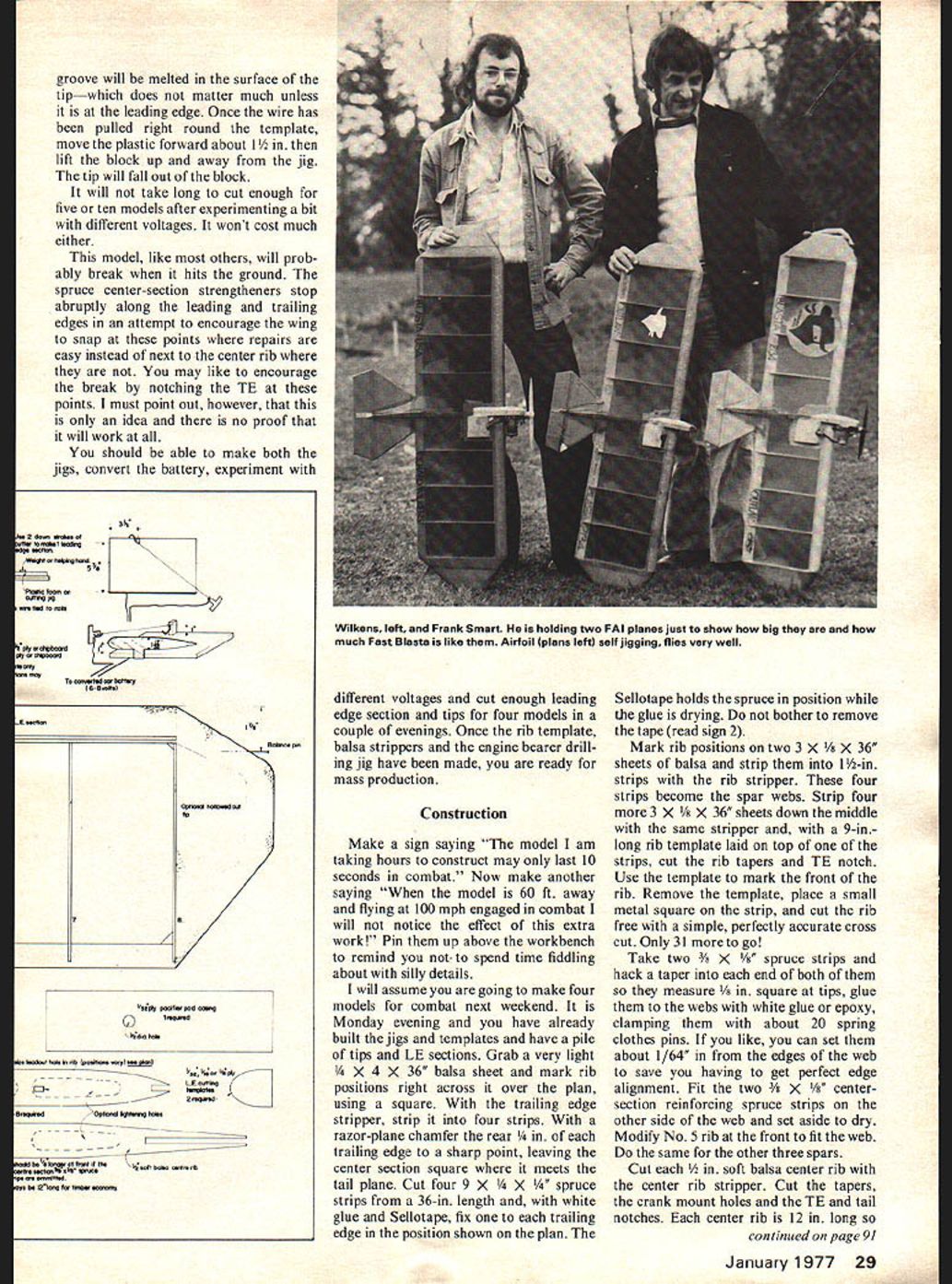
I scaled up a 400 sq. in. FAI Blasta in California and the result, now considerably improved, appears in this article. The original, after having miraculously survived two mid-air collisions and scoring a lucky kill in the second round, was smashed during a fly-off match for 5th place against Greg Hissem who was flying a bit too well. (Editor's Note: Keep in mind that flying our Fast rules was a new experience for Wilkens, comparable to a U.S. modeler flying FAI rules in international competition.)
Compared with the Fast ships you chaps are used to seeing, this one is huge. The flat-section wing which makes flight formula manuals curl up at the edges was discovered in 1965 in Britain and, since then, 99% of all British models have used that type of section. The advantages are that models go together extremely quickly because they are self-jigging, and can be built flat on the building board. They are easy to repair and motor mounts, tips, and tails can be reused when the model gets smashed. The structure makes it easy for one model to be formed from two broken ones. It has fewer components than its U.S. cousin and very few precision fits are required during assembly.
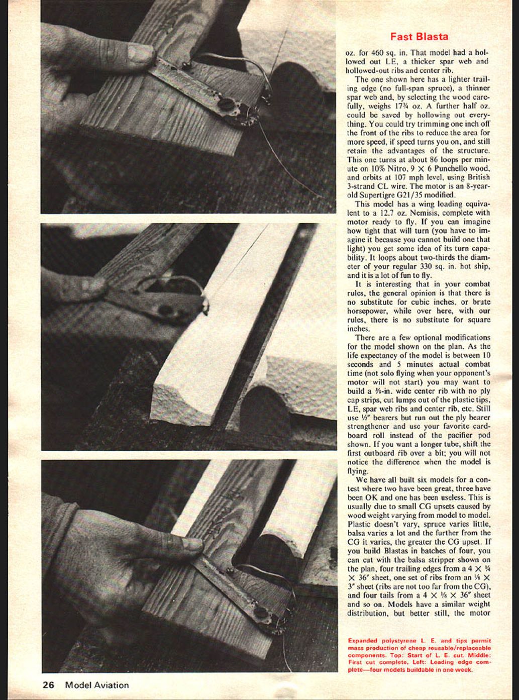
The Blasta expanded polystyrene leading edge and tips are a 1975 invention which allows you to mass produce very cheaply identical reusable/replaceable components — a crushed LE for example, can be cut off and replaced on the field between matches. The one-piece tips copy the wing section and taper it to produce a lift-producing section beyond the 36-in. balsa frame. Tips like these may be made with any wing section and be fitted to any model, thus increasing its aspect ratio and reducing the induced drag of the wing. They may also be hollowed out with a hot knife to make them super light.
In Britain, a contest is held every week between March and October and as this country is about the size of Illinois, no one has far to travel. Everyone enters as many contests as possible, the limiting factor being how quickly they can replenish their stock of models. U.S. structures are thus totally impractical over here as they take too long to build. (Vampires and Shrike II's excepted.)
Because all fliers meet nearly every week, some often take two or three different size models along to the contest so that they may select one to fly against a particular opponent, hoping to out-turn his model by a small amount and be about the same speed — perhaps a bit slower.
This correct selection of model is rather like an expert fisherman selecting the right bait for a certain fish in a certain river. There is no such thing as a universal worm that beats all fish or a universal combat model that beats all others. This is where another great advantage of a flat-section wing comes in because this constructional system allows variation overnight in chord, and therefore area, in your favorite design. Even the plastic tip jig can be used without modification by moving the block of plastic to reduce the length of the tip during cutting. As soon as someone makes a curved wing section, the problem is a lot more difficult to solve as it screws up all your airfoil percentages.
Having never flown Fast Combat before, the sizing of the Fast version was a shot in the dark. The CG was a bit too far back and a 1/2-oz. prop nut was fitted to the Nats' model, bringing its weight up to 19 oz for a 460 sq. in. model.
Fast Blasta
The one shown here has a lighter trailing edge (no full-span spruce), a thinner spar web and, by selecting the wood carefully, weighs 17¾ oz. A further half oz. could be saved by hollowing out everything. You could try trimming one inch off the front of the ribs to reduce the area for more speed, if speed turns you on, and still retain the advantages of the structure. This one turns at about 86 loops per minute on 10% Nitro, 9 X 6 Punchello wood, and orbits at 107 mph level, using British 3-strand CL wire. The motor is an 8-year-old Supertigre G21/35 modified.
This model has a wing loading equivalent to a 12.7 oz. Nemesis, complete with motor ready to fly. If you can imagine how tight that will turn (you have to imagine it because you cannot build one that light) you get some idea of its turn capability. It loops about two-thirds the diameter of your regular 330 sq. in. hot ship, and it is a lot of fun to fly.
It is interesting that in your combat rules, the general opinion is that there is no substitute for cubic inches, or brute horsepower, while over here, with our rules, there is no substitute for square inches.
There are a few optional modifications for the model shown on the plan. As the life expectancy of the model is between 10 seconds and 5 minutes actual combat time (not solo flying when your opponent's motor will not start) you may want to build a 3/8-in. wide center rib with no ply cap strips, cut lumps out of the plastic tips, LE, spar web ribs and center rib, etc. Still use 1/2" bearers but run out the ply bearer strengthener and use your favorite cardboard roll instead of the pacifier pod shown. If you want a longer tube, shift the first outboard rib over a bit; you will not notice the difference when the model is flying.
We have all built six models for a contest where two have been great, three have been OK and one has been useless. This is usually due to small CG upsets caused by wood weight varying from model to model. Plastic doesn't vary, spruce varies little, balsa varies a lot and the further from the CG it varies, the greater the CG upset. If you build Blastas in batches of four, you can cut with the balsa stripper shown on the plan, four trailing edges from a 4 x 1/4 x 36" sheet, one set of ribs from an 1/8 x 3" sheet (ribs are not too far from the CG), and four tails from a 4 x 1/8 x 36" sheet and so on. Models have a similar weight distribution, but better still, the motor mount is put on last, after the model has been covered, and the motor position is adjusted before fixing, so that the correct CG is obtained for every model. Also, if you live in a very windy area in the States you can stick the motor mount on with 1-2° side-thrust for extra line tension upwind. Line tension is another point to be considered because this model loops tighter than the average, centrifugal force is reduced and line whip increases.
The inboard wing is 2 inches longer than the outboard wing to help solve this problem, because it makes the model tend to roll out from the pilot in all flight attitudes.
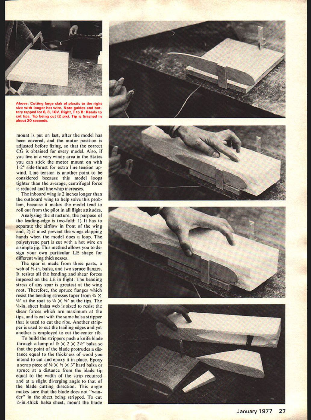
Analyzing the structure, the purpose of the leading-edge is two-fold: 1) It has to separate the airflow in front of the wing and, 2) it must prevent the wings clapping hands when the model does a loop. The polystyrene part is cut with a hot wire on a simple jig. This method allows you to design your own particular LE shape for different wing thicknesses.
The spar is made from three parts, a web of 1/8-in. balsa, and two spruce flanges. It resists all the bending and shear forces imposed on the LE in flight. The bending stress of any spar is greatest at the wing root. Therefore, the spruce flanges which resist the bending stresses taper from 3/8 x 1/8 at the root to 1/8 x 1/8 at the tips. The 1/8-in. sheet balsa web is sized to resist the shear forces which are maximum at the tips, and is cut with the same balsa stripper that is used to cut the ribs. Another stripper is used to cut the trailing edges and yet another is employed to cut the center rib.
To build the strippers push a knife blade through a lump of 1/8 x 2 x 2 1/2 balsa so that the point of the blade protrudes a distance equal to the thickness of wood you intend to cut and epoxy it in place. Epoxy a scrap piece of 1/8 x 1/2 x 3" hard balsa or spruce at a distance from the blade tip equal to the width of the strip required and at a slight diverging angle to that of the blade cutting direction. This angle makes sure that the blade does not "wander" in the sheet being stripped. To cut 1/2-in.-thick balsa sheet, mount the blade with a 1/4-in. protrusion and cut 1/4 in. deep each side of the 1/2-in. sheet. Add Sellotape (or similar) to reduce friction. The strippers are very easy to make and strips are cut in seconds—all exactly the same size.
The polystyrene foam LE is cut with a hot wire made from a piece of old control-line wire heated with a 12V car battery. Both 3- and 7-strand "Laystraight" CL wire available in Britain has been used successfully, so I see no reason why a scrap length of your .018 line cannot be used. If 12V makes the wire too hot, you can modify the battery to tap off 6, 8 or 10V as required.
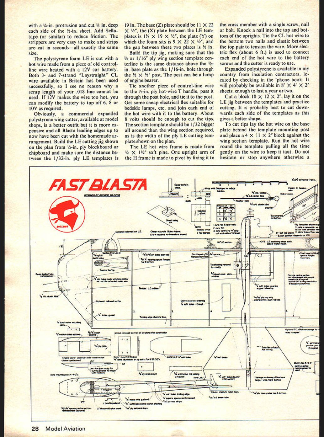
Obviously, a commercial expanded polystyrene wing cutter, available at model shops, is a better outfit but it is more expensive and all Blasta leading edges up to now have been cut with the homemade arrangement. Build the LE cutting jig shown on the plan from 1/2-in. ply, blockboard or chipboard and make sure the distance between the 1/32-in. ply LE templates is 19 in. The base (Z) plate should be 11 x 22 x 1/2", the (X) plate between the LE templates is 1 3/8 x 19 x 1/2", the plate (Y) on which the foam sits is 9 x 22 x 1/2", and the gap between these two plates is 1/2 in.
Build the tip jig, making sure that the 1/4 or 1/16-in. ply wing section template centreline is the same distance above the 1/2-in. base plate as the 1/16-in. hole through the 1/2 x 1/2 post. The post can be a lump of engine bearer.
Tie another piece of control-line wire to the 1/8-in. ply hot-wire T-handle, pass it through the post hole, and tie it to the post. Get some cheap electrical flex suitable for bedside lamps, etc., and join each end of the hot wire with it to the battery. About 8 volts should be enough to cut the tips. The section template should be 1/32 bigger all around than the wing section required, as is the width of the ply LE cutting template shown on the plan.
The LE hot wire frame is made from 1/2 x 1 1/2 soft pine. One upright arm of the H-frame is made to pivot by fixing it to the cross member with a single screw, nail or bolt. Knock a nail into the top and into the top and bottom of the uprights. Tie the CL hot wire to the bottom two nails and elastic between the top pair to tension the wire. More electric flex (about 6 ft.) is used to connect each end of the hot wire to the battery screws and the cutter is ready to use.
Expanded polystyrene is available in my country from insulation contractors, located by checking in the 'phone book. It will probably be available in 8' x 4' x 2' sheets, enough to last a year or two.
Cut a block 18 x 12 x 2", lay it on the LE jig between the templates and practice cutting. It is probably best to cut downwards each side of the templates as this gives a better shape.
To cut tips lay the hot wire on the base plate behind the template mounting post and place a 4 x 11 x 2" block against the wing section template. Run the hot wire round the template, pulling all the time gently on the wire to keep it taut. Do not hesitate or stop anywhere; otherwise a nick will occur and the tip shape will be spoiled. groove will be melted in the surface of the tip—which does not matter much unless it is at the leading edge. Once the wire has been pulled right round the template, move the plastic forward about 1¼ in. then lift the block up and away from the jig. The tip will fall out of the block.
It will not take long to cut enough for five or ten models after experimenting a bit with different voltages. It won't cost much either.
This model, like most others, will probably break when it hits the ground. The spruce center-section strengthen ers stop abruptly along the leading and trailing edges in an attempt to encourage the wing to snap at these points where repairs are easy instead of next to the center rib where they are not. You may like to encourage the break by notching the TE at these points. I must point out, however, that this is only an idea and there is no proof that it will work at all.
You should be able to make both the jigs, convert the battery, experiment with different voltages and cut enough leading edge section and tips for four models in a couple of evenings. Once the rib template, balsa strippers and the engine bearer drilling jig have been made, you are ready for mass production.
Construction
Make a sign saying "The model I am taking hours to construct may only last 10 seconds in combat." Now make another saying "When the model is 60 ft. away and flying at 100 mph engaged in combat I will not notice the effect of this extra work!" Pin them up above the workbench to remind you not to spend time fiddling about with silly details.
I will assume you are going to make four models for combat next weekend. It is Monday evening and you have already built the jigs and templates and have a pile of tips and LE sections. Grab a very light 1/4 x 4 x 36" balsa sheet and mark rib positions right across it over the rib using a square. With the trailing edge stripper, strip it into four strips. With a razor-plane chamfer the rear 1/4 in. of each trailing edge to a sharp point, leaving the center section square where it meets the tail plane. Cut four 9 x 1/4 x 1/4 spruce strips from a 36-in. length and, with white glue and Sellotape, fix one to each trailing edge in the position shown on the plan. The Sellotape holds the spruce in position while the glue is drying. Do not bother to remove the tape (read sign 2).
Mark rib positions on two 3 x 1/8 x 36" sheets of balsa and strip them into 1½-in. strips with the rib stripper. These four strips become the spar webs. Strip four more 3 x 1/8 x 36" sheets down the middle with the same stripper and, with a 9-in. long rib template laid on top of one of the strips, cut the rib tapers and TE notch. Use the template to mark the front of the rib. Remove the template, place a small metal square on the strip, and cut the ribs free with a simple, perfectly accurate cross cut. Only 31 more to go!
Take two 3/8 x 5/8 spruce strips and hack a taper into each end of both of them so they measure 5/8 in. square at tips, glue them to the webs with white glue or epoxy, clamping them with about 20 spring clothes pins. If you like, you can set them about 1/64" in from the edges of the web to save you having to get perfect alignment. Fit the two 3/8 x 1/4 center-section reinforcing spruce strips on the other side of the web and set aside to dry. Modify No. 5 rib at the front to fit the web. Do the same for the other three spars.
Cut each 1/8 in. soft balsa center rib with the center rib stripper. Cut the tapers, the crank mount holes and the TE and tail notches. Each center rib is 12 in. long so
Fast Blasta/Wilkens continued from page 29
you get six out of a 3 x 1/2 x 36" sheet.
Cut the 1/32 in. ply cap strips. The top one incorporates the pushrod slot. White glue and Sellotape again.
Tuesday. Cut the 1/8-in. ply crank mounts, drill the crank bolt holes to suit your 3-in. bellcrank mounting bolts. A British Micromold 3 in. nylon crank is shown on the plan; any crank can be used but use the pushrod hole nearest the bolt. Insert all crank bolts, add cranks, leadouts and pushrods. Make a Z-bend in the 1/16 music wire to prevent it falling out of the crank.
Cut out four delta tails from one 4 x 36 x 1/8" soft balsa sheet and extend the front of each tail by 1 in. by adding a 1 x 1/8" balsa strip to each tail. Or use a 5-in. sheet if you can buy one. Cut 1/4-in. soft balsa elevators and round off all edges with sandpaper. No fancy airfoils—read the signs.
With a tailplane flat on the edge of a table and an elevator at right angles to it laid down over the table edge, stick on the top 1-in. wide Sellotape hinge, pressing the tape into the crack. Turn the lot over and repeat the operation. Bend the elevator up and down a dozen times to check that the hinge is OK and cover one side of the tail and elevator with a single piece of Fascal or Solarfilm, again with the elevator at right angles to the tail. Turn over and repeat.
Number the ribs and cut leadout holes in them. Use white glue or Hot Stuff for assembly of all components, except LE's and tips may not be fixed with Hot Stuff.
First, stick all ribs including the center ribs onto the trailing edges, using the plan as a guide. Remove all pegs from the spars, lay the spars front end down on the building board and up end all rib/T/E assemblies, dropping them vertically into position on the spars and crosspinning the ribs while the white glue sets. Make sure the tip ribs are square with the spar when viewed from the rear, otherwise you may get unwanted tip dihedral.
Remove some covering from the tailplanes where they touch the center ribs, cut out the 1/16-in. balsa tail packing pieces, glue them to the tailplanes, and glue the tailplanes to the center ribs and TEs. You should not have spent more than eight hours total time reaching this stage.
White glue and Sellotape (or pin) the LE section in place and trim the ends flush with the tip ribs, using a knife or razor-plane with a new blade in it. Make the leadout holes through the inboard tips with a rat-tail file, or use a hot pushrod to melt a 1/8-in. dia. hole. (This takes practice so try it first on a scrap chunk of foam.)
In go the 1-in. long 1/8-in. dia. aluminum, brass or copper leadout tubes. Epoxy these in place and smear epoxy round the holes and round the edge of the tip to reinforce the plastic as shown on the plan. Fix tips in place with epoxy or with white glue.
Wednesday. In go the control assemblies, the 1/2 x 1/2 x 1/32" ply bellcrank stops and the center-section sheeting. Make up the pacifier pods, fix them in place, and add the covering support strips (1/8" balsa).
After removing some covering from the elevator, epoxy the 1/32-ply horn mounting plates in place. Add the balsa tip gussets shown on the plan, glue on the tips and sand wing to final shape. Fill small gaps with super-glue. Put a strip of 1/32" ply under the motor bearers and epoxy those in place. First fit the engine to see where the bearers should be. Install the radio components and check the balance. You may find the CG is a little tailheavy; if so, add weight to the nose or move the motor forward. sets, sandpaper the frame smooth, spending about five minutes for each model (there is not much to sandpaper). Add the Fascal or Solarfilm tail fairings top and bottom.
Thursday. Test the iron temperature on a scrap chunk of plastic, so as not to melt the LE and tips, and cover the models using separate pieces for the tips. (Note: You cannot cover the model with silk, paper or nylon because dope melts the polystyrene. I suppose you could cover the tips and the LE first with paper glued on with diluted white glue but it is not worth the time!)
Remember that heat melts the polystyrene. Go steady with the heat gun or iron when shrinking the covering. Dewarping the wing over the gas stove or in front of an electric fire is a bit risky, unless you mask the LE and tips from the heat with sheet balsa or a chunk of cardboard.
Friday. Cut a 1 1/32-in. wide section of leading edge away back to the spar to allow the motor mount to butt up against it; remove some covering under where the bearers will fit the wing.
The 1/32-in. ply plate eases construction and increases the strength of the motor mounts. Mark the bearer and spacer positions on the ply and build the engine bearer assemblies. Trim the ply away between the bearers where they fit over the wing spar and Sellotape the nacelles to the assemblies along with the motor, prop and motor-mount bolts, nuts and plates. Slide an assembly onto a model and test for the CG with pins set back from the leading edge as shown on the plan. Adjust motor position to obtain CG trimming the bearer spacers and leading edge as required. Remove assembly. Drill bolt holes. Using the drilling jig as a guide, fit some 4-40 blind-mounting nuts and epoxy the nacelle to the bearer assemblies, and then the complete mounts to the wings.
Side-thrust is easily obtained, if you want it, by sticking the mounts on with 1° or 2° offset, but this is not necessary unless you fly in very windy conditions. Drill a 3/16-in. hole right through the bearers, center rib and crank mount as shown on the plan, and insert the 3/16-in. dia. dowel which prevents the crank mount leaving the model during the pull test. Repeat this procedure for the three other models.
The 1/8 dural engine mounting plates shown on the plan can cut out vibration and make it unnecessary to cut the ply under the crankcase. They are not glued to the bearers or motor.
Two coats of dope and one of fuel proofer are applied to the mounts after an epoxy fillet has been smeared round the motor-mount/leading-edge joint to prevent progress of polystyrene solvents (dope and glass fiber resin). Glass fiber need not be applied; the ply stops the bearers from cracking up.
Fuel-proof the 1/32 ply horn mounting plates on the elevator, and fuel-proof the inside of the fuel pod.
Saturday morning. You've done very well considering you aren't familiar with this model. All you have to do now is to fit a nylon control horn (Kavan medium is shown), and connect the Kwik-Link to the pushrod and horn. Dewarp the model before flying using steam from a kettle or a heat gun.
Flying
Fly the model level and check that it isn't banking in or out. Fly inverted and check the same. If the line tension is different now, or the outboard tip is visible, you missed removing the warp. Remove it before flying any tight turns or the model may crash.
When all warps have been removed, fly wide consecutive loops and tighten them up as much as possible. Note whether or not the outboard wing suddenly drops and flies wider loops than the inboard wing, with a simultaneous 15-20% reduction in airspeed. If all this happens, the wing has stalled because there is too much elevator movement. Try the same procedure with outsides before landing. If it drops a wing in one loop direction only, reduce the elevator throw in the stalling direction and retry. If it still stalls, move the link to a higher hole in the horn. (You will need more elevator movement on windy days.) If you are not satisfied with the turn performance, then add weight to the tail until you are. (Wrap solder round the horn.) But make sure the model doesn't become directionally unstable after doing this. It must still be able to be flicked into rock-steady level flight. It may be advantageous when building a batch of models to test fly one to find the CG position that suits you best, before glueing the motor mounts on all other models.
You chaps know much more about Honking .35s than I do, so you must experiment to find the best prop and fuel to suit your needs. The model is not intended to fly super fast. It is intended to turn so the prop you fit must be of lesser pitch than you normally use, so the motor is in the "right gear" for those sharp corners. I used a 9/6 Rev Up wood at the Nats on 20% fuel and got about 95 to 100 mph level. It turned about the same speed as all the honking streamlined ships even then.
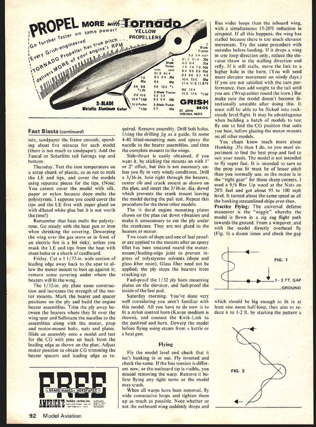
Practice Flying: The universal defense maneuver is the "wiggle" whereby the model is flown in a zig zag flight path towards the ground. From a wingover, and with the model directly overhead fly (Fig. 1) a dozen times and check the gap which should be big enough to fit in at least one more half-loop, then aim to reduce it to 1-2 ft, by starting the pattern a little lower each time until you can fly right under an opponent and pull up between his model and the ground. The technique is to try to get inside his turning circle and force him to overshoot. The idea that I should enter the 1975 U.S. Nats came when Charlie Johnson, Gary Frost and I met at the British Nats in May 1975. I had already booked a peaceful hitch-hike tour of the little old country, and Charlie suggested I should visit him in California before the Nats. Boxed five FAI Blastas left over from the British International headed west. Charlie and Lorna gave plenty of advice.
Fast Combat hadn’t been on my patch before, and I doubt I could have entered the Nats had I not scaled up a 400 sq in Blasta. As a result the design is now considerably improved. The model miraculously survived two mid-air collisions, scored a lucky kill in the second round, and was smashed during the fly-off match for 5th place against Greg Hissem, who was flying a bit too well.
Editors note: Keep in mind flying Fast rules is a new experience. Wilkens’ model is comparable to the U.S. models flown under FAI rules in international competition.
Compared to the Fast ships you chaps are used to seeing, the huge flat-section wing is a major difference. The section, discovered in Britain about 1965, has been used on about 99% of British models since then. The advantages are obvious: models go together extremely quickly because of the self-jigging nature of the construction; they can be built flat on a building board; repairs to motor mounts, tips and tails are straightforward and parts can be reused if the model is smashed. The structure makes for easy repairs — two broken ones can be made into one sound model. The Blasta has fewer components than its U.S. cousin and very few precision fits are required during assembly.
The Blasta uses expanded polystyrene leading-edge tips — a 1975 invention of the world’s respected FAI combat fliers — which adapts the famous Blasta to American Fast Combat rules. This allows mass production of very cheap, identical, reusable/replaceable components. If the LE is crushed, for example, it can be cut off and replaced in the field between matches. One-piece tips can copy the wing section taper and produce a lift-producing section beyond the 36‑in balsa frame. Tips may also be made as a wing section fitted to the model, thus increasing its aspect ratio and reducing induced drag. The wing may also be hollowed out with a hot knife to make it super-light.
British contests are held in weeks between March and October — the country is about the size of Illinois, and no one has far to travel. Everyone enters every contest possible, and the limiting factor is often how quickly you can replenish stock models. U.S. structures are therefore totally impractical here because they take too long to build, Vampires and Shrika IIs excepted. Because fliers meet nearly every week, some often take two or three differently sized models along; during a contest they may select which to fly against a particular opponent, hoping to out-turn him. A small amount of difference, about the same speed or perhaps a bit slower, may be the deciding factor. Correct selection of model is rather like an expert fisherman selecting the right bait for a certain fish in a certain river — there is no universal bait; just as there is no universal combat model that beats all others.
Another great advantage of the flat-section wing is the constructional system allows easy variation of chord and therefore wing area overnight. A favorite design aid is a plastic-tip jig that can be used without modification; by moving a block of plastic you reduce the length of tip being cut. Once someone makes a curved wing section the problem becomes a lot more difficult to solve and they risk screwing up the airfoil percentages.
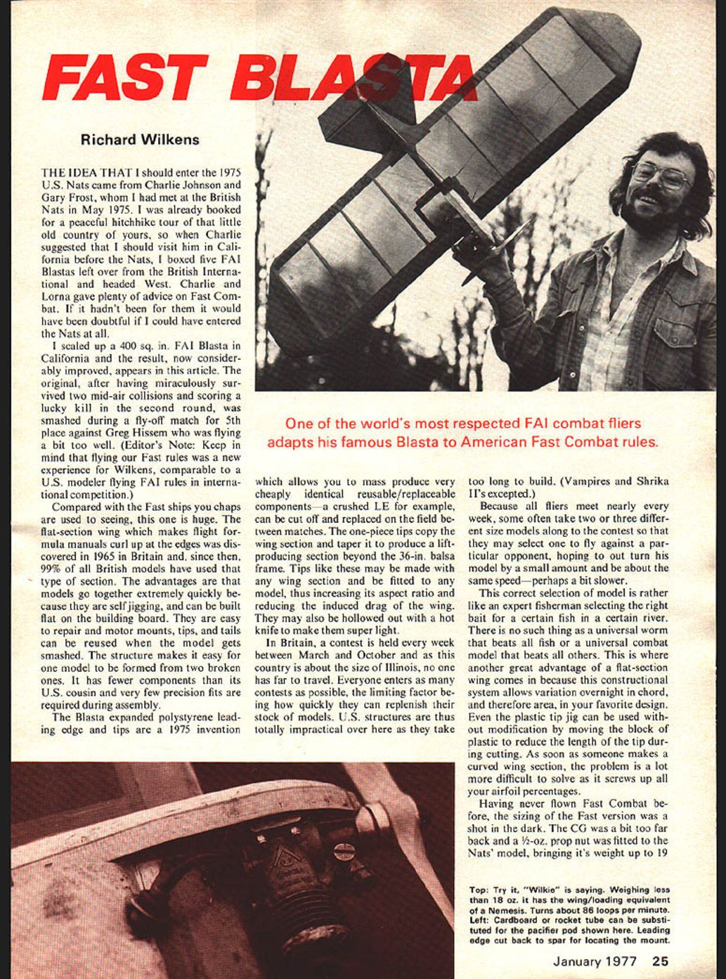
Having never flown Fast Combat before, when sizing the Fast version I set the CG a bit too far back. A 1/2 oz prop nut fitted to the Nats model brought its weight up to 19 oz. Try to keep weight down — one weighing less than 18 oz has a wing loading equivalent to a Nemesis and turns about 86 loops per minute.
Cardboard rocket tube can be substituted for the pacifier pod shown. The leading edge is cut back for spar locating and mount.
For a 460 sq in model with the hollowed-out LE and a thicker spar web, hollowed-out ribs and a center rib with a lighter trailing edge (no full-span spruce, thinner spar web and careful wood selection), the weight comes to about 17 oz. A further half-ounce could be saved by more hollowing. You could try trimming 1/8 in off the front ribs to reduce area and increase speed yet still retain structural advantages. Such a model turns about 86 loops per minute on 10% nitro with a 9 x 6 wooden prop and punches out about 107 mph level using a British 3-strand CL wire motor. An 8-year-old Supertigre G21/35 modified motor gives the model a wing-loading equivalent to 12.7 oz/sq ft.
The Nemesis-complete motor ready-to-fly gives an idea of the tight turning ability you can expect. If you cannot build extremely light, you can at least get some idea of its turning capability: loops about two-thirds the diameter of a regular 330 sq in hot ship. It’s a lot of fun to fly and the Fast combat rules make for interesting contests. In general opinion, there is no substitute for experience.
Transcribed from original scans by AI. Minor OCR errors may remain.

