


FREE FLIGHT DURATION
Louis Joyner, 6 Saturday Rd., Mt. Pleasant SC 29464
ON STABS AND STABILITY:
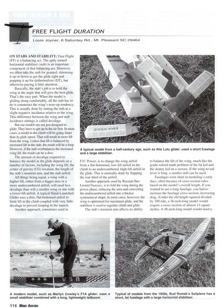
Free Flight (FF) is a balancing act. The aptly named horizontal stabilizer (stab) is an important component of that balancing act. However, we often take the stab for granted, shimming it up or down to get the glide right and popping it up for dethermalizer (DT), but otherwise paying it little attention.
Basically, the stab's job is to hold the wing at the angle that will give the best glide. That's the easy part. When the model is gliding along comfortably, all the stab has to do is counteract the wing's nose-up tendency. This is usually done by setting the stab at a slight negative incidence relative to the wing. This difference between the wing and stab incidence settings is called decalage.
But our models are not just designed to glide. They have to get up in the air first. In most cases, a model in the climb will be going faster than its glide speed. That will result in more lift from the wing. Unless that lift is balanced by increased lift in the stab, the result will be a loop. However, if the stab overbalances the increased wing lift, the result can be a dive.
The amount of decalage required to balance the model in the glide depends on a number of factors, including the wing lift, the center of gravity (CG) location, the length of the stab's moment arm, and the stab airfoil. All things being equal, a wing with a higher lift, either from a bigger area or a more undercambered airfoil, will need less decalage than will a smaller wing or one with a lower-lift airfoil. A typical Hand-Launched Glider uses a thin, flat-bottomed airfoil to limit lift in the climb coupled with very little decalage to prevent looping in the launch.
Another approach, sometimes used in F1C Power, is to change the wing airfoil from a flat-bottomed, low-lift airfoil in the climb to an undercambered, high-lift airfoil in the glide. This is normally done by flapping the rear third of the airfoil. Another approach, used by Russian flier Leonid Fuzeyev, is to fold the wing during the power phase, reducing the area and converting the undercambered airfoil into a thicker symmetrical shape. In most cases, however, the wing is optimized for maximum glide, and the stabilizer is used to regulate climb and glide.
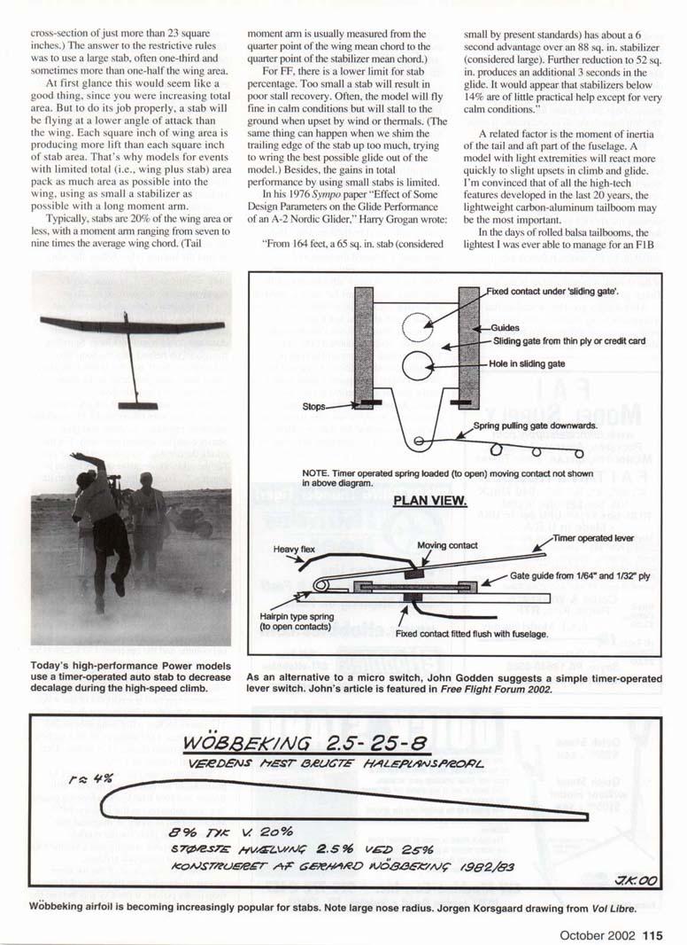
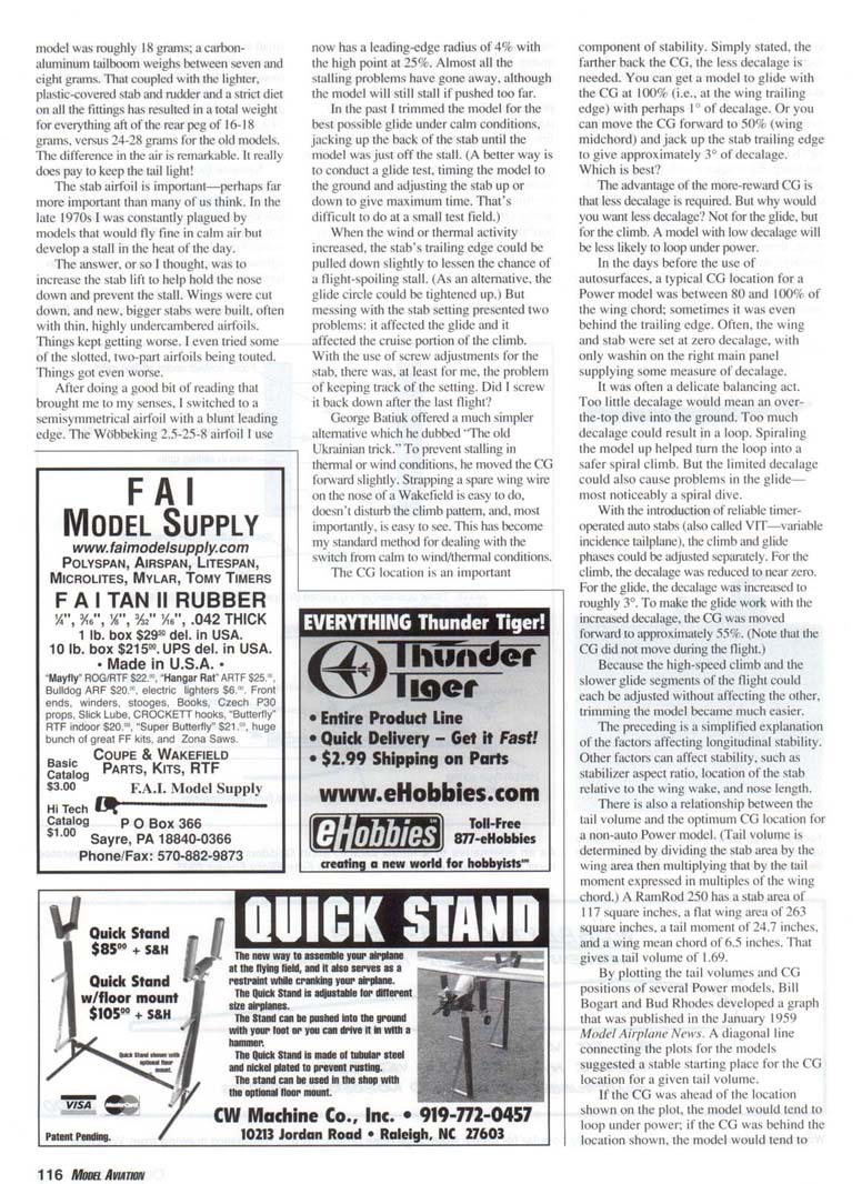
The stab's moment arm affects its ability to balance the lift of the wing, much like the grade-school math problem of the fat kid and the skinny kid on a seesaw. If the wing-to-tail lever is long, a smaller stab can be used. Fuselages were short in modeling's early days, often because of cross-section rules based on the model's overall length. If you wanted to use a long fuselage, you had to increase the fuselage cross-section, increasing drag. (Under the old length-squared divided by 100 rule, a 36-inch-long model would require a cross-section of almost 13 square inches. A 48-inch-long model would need a cross-section of just more than 23 square inches.) The answer to the restrictive rules was to use a large stab, often one-third and sometimes more than one-half the wing area. At first glance this would seem like a good thing, since you were increasing total area. But to do its job properly, a stab will be flying at a lower angle of attack than the wing. Each square inch of wing area is producing more lift than each square inch of stab area. That's why models for events with limited total (i.e., wing plus stab) area pack as much area as possible into the wing, using as small a stabilizer as possible with a long moment arm. Typically, stabs are 20% of the wing area or less, with a moment arm ranging from seven to nine times the average wing chord. (Tail moment arm is usually measured from the quarter point of the wing mean chord to the quarter point of the stabilizer mean chord.) For FF, there is a lower limit for stab percentage. Too small a stab will result in poor stall recovery. Often, the model will fly fine in calm conditions but will stall to the ground when upset by wind or thermals. (The same thing can happen when we shim the trailing edge of the stab up too much, trying to wring the best possible glide out of the model.) Besides, the gains in total performance by using small stabs is limited.
In his 1976 Sympo paper "Effect of Some Design Parameters on the Glide Performance of an A-2 Nordic Glider," Harry Grogan wrote:
"From 164 feet, a 65 sq. in. stab (considered small by present standards) has about a 6 second advantage over an 88 sq. in. stabilizer (considered large). Further reduction to 52 sq. in. produces an additional 3 seconds in the glide. It would appear that stabilizers below 14% are of little practical help except for very calm conditions."
A related factor is the moment of inertia of the tail and aft part of the fuselage. A model with light extremities will react more quickly to slight upsets in climb and glide. I'm convinced that of all the high-tech features developed in the last 20 years, the lightweight carbon-aluminum tailboom may be the most important. In earlier days, with rolled balsa tailbooms, tail moment-of-inertia was higher and the models were less forgiving. Modern lightweight tailbooms have reduced those problems: almost all the stalling issues have gone away, although the model will still stall if pushed too far.
In the past I trimmed the model for the best possible glide under calm conditions, jacking up the back of the stab until the model was just off the stall. (A better way is to conduct a glide test, timing the model to the ground and adjusting the stab up or down to give maximum time. That's difficult to do at a small test field.)
When the wind or thermal activity increased, the stab's trailing edge could be pulled down slightly to lessen the chance of a flight-spoiling stall. (As an alternative, the glide circle could be tightened up.) But messing with the stab setting presented two problems: it affected the glide and it affected the cruise portion of the climb. With the use of screw adjustments for the stab, there was, at least for me, the problem of keeping track of the setting. Did I screw it back down after the last flight?
George Batluk offered a much simpler alternative which he dubbed "the old Ukrainian trick." To prevent stalling in thermal or wind conditions, he moved the CG forward slightly. Strapping a spare wing wire on the nose of a Wakefield is easy to do, doesn't disturb the climb pattern, and, most importantly, is easy to see. This has become my standard method for dealing with the switch from calm to wind/thermal conditions.
The CG location is an important component of stability. Simply stated, the farther back the CG, the less decalage is needed. You can get a model to glide with the CG at 100% (i.e., at the wing trailing edge) with perhaps 1° of decalage. Or you can move the CG forward to 50% (wing midchord) and jack up the stab trailing edge to give approximately 3° of decalage. Which is best?
The advantage of the more-rearward CG is that less decalage is required. But why would you want less decalage? Not for the glide, but for the climb. A model with low decalage will be less likely to loop under power.
In the days before the use of autosurfaces, a typical CG location for a Power model was between 80 and 100% of the wing chord; sometimes it was even behind the trailing edge. Often, the wing and stab were set at zero decalage, with only washout or preset reflex supplying some measure of decalage.
There are three ways to change the effective decalage. Too little decalage could mean an over-the-top dive into the ground. Too much decalage could result in a loop. Spiraling the model up helped turn the loop into a spiral climb. But the limited decalage could also cause problems in the glide — most noticeably a spiral dive.
With the introduction of reliable time-operated auto stabilizers (also called VIT — variable incidence tailplane), the climb and glide phases could be adjusted separately. For F1B, automatic stab was reduced to near zero. For the glide, decalage was increased to roughly 3°. To make the glide work with the increased decalage, the CG was moved forward to approximately 55%. (Note that the CG did not move during the flight.)
Because the high-speed climb and the glide have very different speeds and angle-of-attack requirements, it is difficult to design a single passive geometry that is optimal for both phases. Other factors can affect lateral stability, such as stabilizer aspect ratio, location of the stab relative to the wing wake, and moment arm. There is also a relationship between the tail area and the optimum CG location for non-auto Power models. (Tail volume is the tail area times the moment arm, divided by the wing area; the stabilizer area is the area of the stab expressed in multiples of the wing chord.) A RamRod 205 has a stab area of 117 square inches, a tail area of 26.7 inches, and a wing mean chord of 6.5 inches. That gives a tail volume of 1.69.
By plotting the tail volume and CG positions of several Power models, Bill Bogart and Bud Rhodes developed a graph that was published in the January 1959 Model Airplane News. A diagonal line connecting the plots for the models suggested a stable starting place for the CG location for a given tail volume.
If the CG was ahead of the location shown on the plot, the model would tend to loop under power; if the CG was behind the location shown, the model would tend to dive under power. The decalage would need to be adjusted to the glide based on the CG location and tail moment arm.
If I have learned one thing in the last 20 years, it is to check the CG if you have problems with stalling or a too-fast glide. If the CG is in the right place, then and only then should you start moving the stab trailing edge up or down. If the CG is not in the right place, break out the lead.
The flying field is not the place to check the CG. Do it in the shop, out of the wind. Balancing the model on your fingertips is not accurate enough. A simple knife-edge fixture of balsa will allow you to adjust the CG to within 1% of the chord. Remember too that the CG should be based on the wing's average chord—not its root chord. You also need to allow for tapered or back-swept wings.
Once you determine the correct CG location for your model, mark it on the bottom of the wings. Remember to check the CG from time to time. Repairs and patches can cause a shift, usually to the rear.
Transcribed from original scans by AI. Minor OCR errors may remain.

