
FF Power Model TRIM Part I
Bob Johannes
The problem of trimming (adjusting) powered Free Flight models has been with us since the first Brown engine fired up and hauled a model skyward. The goal is to reach the best compromise among diverse flight conditions: the relatively high-speed flight during engine run and the slow, floating glide.
As engines became more powerful, model designs evolved and trim techniques had to change. The trim philosophy presented here is the result of several years of personal experimentation and the advice of many expert modelers. It applies to modern Free Flight designs and to older designs as well. I have successfully used this philosophy on an Ohlsson .60–powered New Ruler; an Ohlsson .23–powered Brooklyn Dodger; K&B Greenhead–powered Ramrods; and several modern high-powered AMA gas Free Flight models.
Trimming starts before you ever get to the flying field. Proper setup is essential.
Flight segments and objectives
Consider the objectives: the flight can be divided into three distinct but related segments:
- Climb (power pattern)
- Transition to glide
- Glide pattern
The model must:
- Have a stable, consistent, relatively steep climb. The steepness varies with power-to-weight ratio.
- Transition smoothly from the high-speed climb to the slow, floating glide with no dips, stalls, or loss of altitude.
- Glide in a circular pattern, with the turn small enough to enter thermals but as open as possible for good glide efficiency.
Achieving the optimum flight requires compromises in all three segments; they must be addressed simultaneously for the best overall performance. (Variable Incidence Tailplane [VIT]/auto-rudder–equipped models allow greater separation among the segments.)
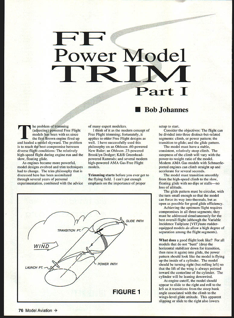
What does a good flight look like?
- For models that do not "bunt" into glide, the power pattern should appear as if the model is flying up the inside of a cylinder, turning right (but rolling left) so the wing lift is always pointed toward the cylinder centerline. The cylinder will be leaning downwind.
- At engine cutoff, the model should appear to slide to the right and roll to the left as it transitions from the steep bank of the climb to a wings-level glide attitude. This right slide lowers the wing’s angle of attack; the roll tendency helps the wing reestablish lift in the glide.
- The flow should be smooth and slow, producing the floating glide for which Free Flight models are renowned.
Trim philosophy — use this as the basis:
- Right-right pattern — the model turns right under power and right in glide.
- Use decalage (incidence difference between wing and tail) and rudder tab as the primary adjustments for the power pattern.
- Use center of gravity (CG) location to establish the turn radius in the glide trim.
Definitions and axes
Directions (right, left, up, down) refer to motions as seen from the seated-cockpit view. The model rotates about three principal axes:
- Pitch axis — axis about which the model raises or lowers its nose. Principal trim input: horizontal stabilizer. Stab trailing edge up (up-elevator) raises the nose; trailing edge down lowers it.
- Roll axis — axis about which the model raises or lowers a wing. Rotations about this axis are principally controlled by wing twist. A right wing with the leading edge up will cause the model to roll left. Terms:
- Washin: increases incidence (leading edge down relative to rest of wing).
- Washout: decreases incidence (leading edge up relative to rest of wing).
- Remember: washin increases the incidence angle of the flying surface relative to the airflow.
- Yaw axis — axis about which the model swings its nose right or left. Principal trim input: rudder or rudder tab.
Why washin on the right wing?
Any model intended to turn right under power must have washin in the right wing to induce the left roll that prevents spiraling into the ground from the natural right-turn tendency of pylon-like power runs. Some plans omit the twist; designers may have considered it a trim adjustment rather than a construction element. If plans call for washout in tip panels, take care to make twist equal in both tips unless differential washout is specified. For fixed-surface models, do not use differential twist unless required.
Covering and shaping tips
- Older models may require you to warp twist into the wing after covering. A heat gun used on modern heat-shrink plastic coverings also works on doped tissue or silk.
- Dried dope is thermoplastic: it softens when heated and will take a new shape; when it cools it holds that shape.
- Tissue and silk add stiffness; a double-covered wing can be very stiff.
- Use a heat gun or sealing iron to remove wrinkles and unwanted warps. When using a heat gun, punch a tiny hole in the covering with a pin where necessary to avoid bubbling.
Lateral wing balance
- Balance the wing laterally. Hold it inverted at the center dihedral break and add lead to the light tip until the wing balances.
- A model will want to turn toward the heavy tip; this can interfere with trim adjustments. I usually balance the wing before covering so the lead is concealed inside.
Accurate construction of other components
- Fuselage straightness:
- The fuselage must be straight. Build on a flat board and draw a top centerline for pylon and fin alignment.
- A slight bow up or down is easier to accommodate than side-to-side bow.
- During trial-fitting, use a line level on the side of the pylon and fin to verify alignment.
- Horizontal stabilizer:
- The stab must be flat—no twist. Stabs may bow upward at the tips when covered; a small bow is acceptable, but eliminate twist.
- Use a heat gun to remove unwanted twist.
Model setup: alignment, CG, decalage, thrust offsets
The setup consists of:
- Properly aligning the wing and tail with the fuselage
- Correctly locating the center of gravity (CG)
- Setting up the proper wing/tail decalage
- Checking engine-thrust offsets
Wing alignment procedure:
- Stick a pin in the top of the fin (rear centerline) or use another fixed reference.
- Use a length of non-stretch cable with a loop. Mount the wing on the pylon, put the cable loop over the pin, and measure to a convenient point (e.g., polyhedral joint at the trailing edge) on each wing.
- Adjust until these distances are equal, then "key" the wing so it always fits the fuselage in the same alignment (small glued split dowel pieces are commonly used as keys).
- Keying the tail is not necessary unless the fin is built into the tail (as in many Nostalgia and Old-Timer models), where keying is essential for consistent fin alignment.
Stab tilt and VIT:
- For fixed-surface models, provide stab tilt for the glide turn. Stab tilt efficiently adjusts glide turn with little effect on the power pattern. A good starting point is to tilt the stab until it aligns with the inboard panel of the right wing; more tilt gives a tighter turn.
- On VIT models, keep the stab level and provide the glide turn with the auto rudder.
- For Old-Timer models, a free-floating drag flap on the right wing trailing edge can be used. The flap streamlines on the power run and kicks out to give drag in the glide, improving glide turn without affecting the power pattern.
- To tighten the turn, add weight to the flap.
- To open the turn, reduce flap size.
- Example flap sizes: Class B Brooklyn Dodger flap = 1½ x 1 in; Class C New Ruler flap = 2 x 3 in.
Balancing the model and CG:
- Use sharp supports to check balance — fingertips are not accurate enough. I use two pieces of 1/4 x 1 molding material tacked to the bench with tapered rounded contact surfaces.
- Put the CG where shown on the plans by adding weight as necessary.
- Typical CG locations:
- Nostalgia and modern AMA models: 75–85% of wing chord behind the leading edge.
- Old-Timer models: 50–55%.
- VIT models: 55–65%.
Decalage (wing-to-tail incidence difference):
- For fixed-surface models, it is typical for the wing to have 1½–2° more incidence than the stab. Many plans don’t give this information reliably; small construction variations make measuring decalage important.
- On VIT models there are two decalage settings: power trim ≈ 1°, glide trim ≈ 2°.
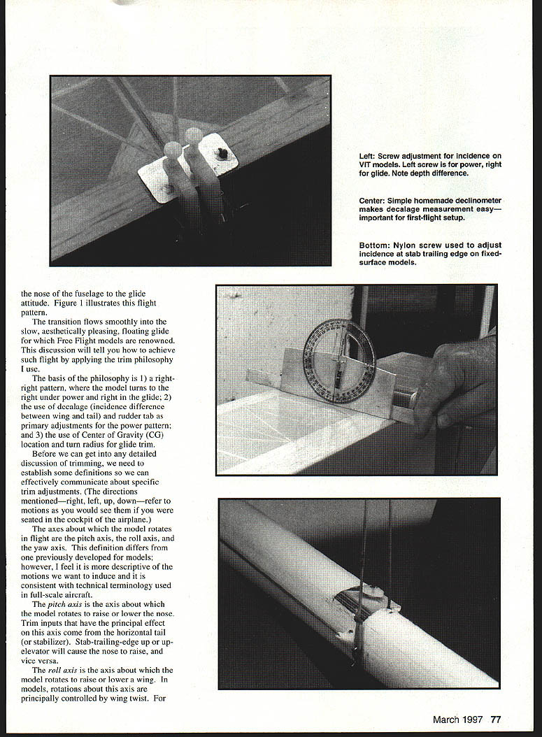
- To measure decalage, use an inclinometer made from a circular protractor glued to a piece of plywood with a straight edge. Drill a small hole at the center and insert a short tube (e.g., Teflon tubing). Place the inclinometer at the bottom of the wing and tail to get the angular difference. This measures the difference (decalage) reliably even if it isn’t a true absolute incidence measurement.
- To adjust decalage:
- Use thin plywood or metal shims under the leading or trailing edge of the stab until desired measurement is attained.
- On high-powered AMA models, a nylon screw under the stab trailing edge (threaded into plywood set in the fuselage) allows easy, repeatable adjustment. The stab rests on the screw head and is held by DT-line tension. This permits changing decalage by a known amount during contest flying.
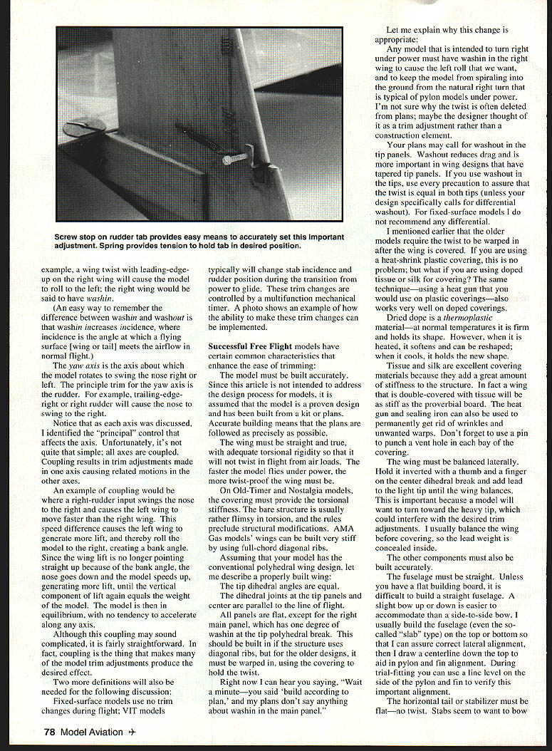
- A screw adjustment on the rudder tab is also useful. Start flying with the rudder tab centered.
Engine thrust offsets:
- I usually start with the thrustline straight ahead — no upthrust or downthrust and no side thrust.
- Historically, thrust offsets were common, but with more powerful engines causing rapid acceleration, thrust offsets affect only the initial phase of the power run before aerodynamic forces dominate.
- You may still need a small left thrust when fully trimmed; this will be discussed further when we get to flying.
Final remarks
If you have followed this procedure, you can be reasonably confident your airplane will not crash on first flights. Successful trimming really does start with careful building and setup.
We are now ready to take the model to the flying field. Part II of this trim philosophy will appear in the May 1997 issue.
Transcribed from original scans by AI. Minor OCR errors may remain.

