
FIGHTERS TWO
Contemporary in the pre-war days, the Japanese 'Nate' and the American P-26 'peashooter' make colorful subjects for Half-A power. Anyone for mock combat? Fred Reese
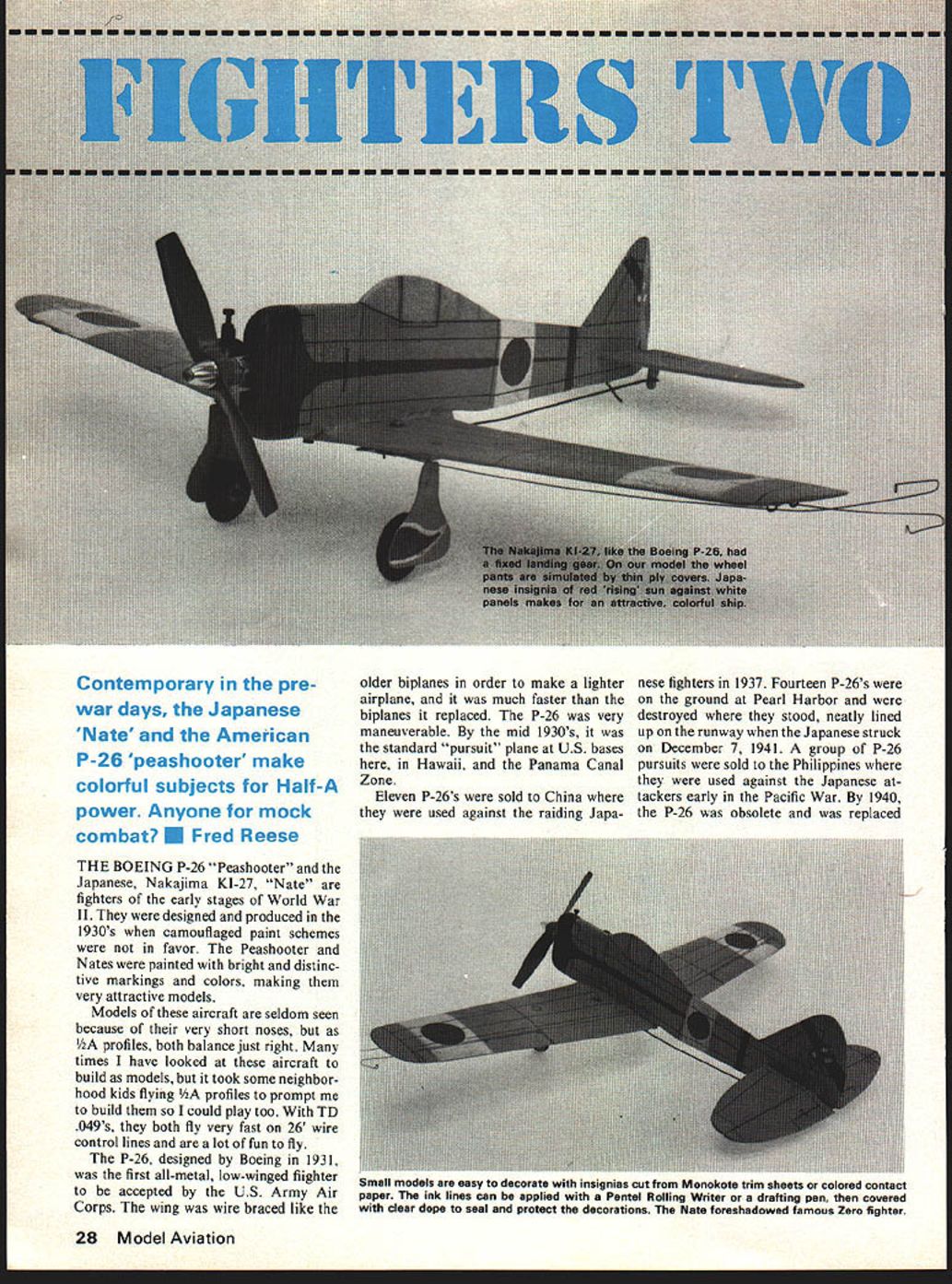
THE BOEING P-26 "Peashooter" and the Japanese, Nakajima KI-27, "Nate" are fighters of the early stages of World War II. They were designed and produced in the 1930's when camouflaged paint schemes were not in favor. The Peashooter and Nates were painted with bright and distinctive markings and colors, making them very attractive models.
Models of these aircraft are seldom seen because of their very short noses, but as 1/2A profiles, both balance just right. Many times I have looked at these aircraft to build as models, but it took some neighborhood kids flying 1/2A profiles to prompt me to build them so I could play too. With TD .049's, they both fly very fast on 26' wire control lines and are a lot of fun to fly.
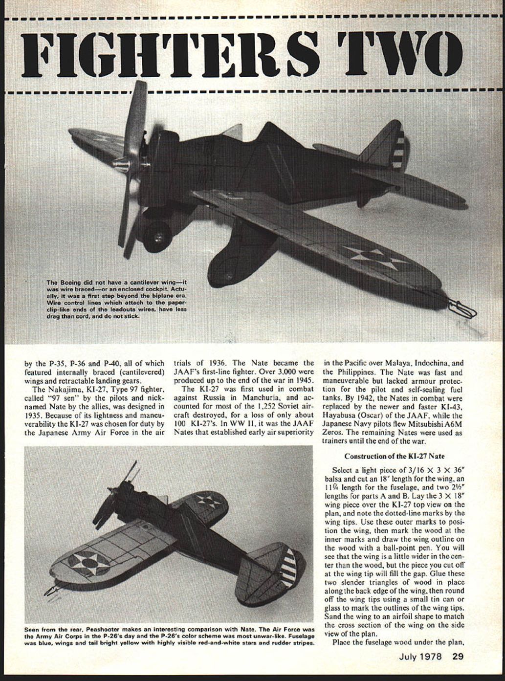
The P-26, designed by Boeing in 1931, was the first all-metal, low-winged fighter to be accepted by the U.S. Army Air Corps. The wing was wire braced like the older biplanes in order to make a lighter airplane, and it was much faster than the biplanes it replaced. The P-26 was very maneuverable. By the mid 1930's, it was the standard "pursuit" plane at U.S. bases here, in Hawaii, and the Panama Canal Zone.
Eleven P-26's were sold to China where they were used against the raiding Japanese fighters in 1937. Fourteen P-26's were on the ground at Pearl Harbor and were destroyed where they stood, neatly lined up on the runway when the Japanese struck on December 7, 1941. A group of P-26 pursuits were sold to the Philippines where they were used against the Japanese attackers early in the Pacific War. By 1940, the P-26 was obsolete and was replaced by the P-35, P-36 and P-40, all of which featured internally braced (cantilevered) wings and retractable landing gears.
The Nakajima, Ki-27, Type 97 fighter, called "97 sen" by the pilots and nicknamed Nate by the Allies, was designed in 1935. Because of its lightness and maneuverability the Ki-27 was chosen for duty by the Japanese Army Air Force in the air trials of 1936. The Nate became the JAAF's first-line fighter. Over 3,000 were produced up to the end of the war in 1945.
The Ki-27 was first used in combat against Russia in Manchuria, and accounted for most of the 1,252 Soviet aircraft destroyed, for a loss of only about 100 Ki-27s. In WWII, it was the JAAF Nates that established early air superiority in the Pacific over Malaya, Indochina, and the Philippines. The Nate was fast and maneuverable but lacked armour protection for the pilot and self-sealing fuel tanks. By 1942, the Nates in combat were replaced by the newer and faster Ki-43, Hayabusa (Oscar) of the JAAF, while the Japanese Navy pilots flew Mitsubishi A6M Zeros. The remaining Nates were used as trainers until the end of the war.
Construction of the KI-27 Nate
Select a light piece of 3/16 x 3 x 36" balsa and cut an 18" length for the wing, an 11-1/4" length for the fuselage, and two 2-1/2" lengths for parts A and B. Lay the 3 x 18" wing piece over the Ki-27 top view on the plan, and note the dotted-line marks by the wing tips. Use these outer marks to position the wing, then mark the wood at the inner marks and draw the wing outline on the wood with a ball-point pen. You will see that the wing is a little wider in the center than the wood, but the piece you cut off at the wing tip will fill the gap. Glue these two slender triangles of wood in place along the back edge of the wing, then round off the wing tips using a small tin can or glass to mark the outlines of the wing tips. Sand the wing to an airfoil shape to match the cross section of the wing on the side view of the plan.
Place the fuselage wood under the plan, align the bottom, front and back and pin, then go around the fuselage outline, sticking a pin through the plan into the wood to mark the outline (shown in photograph). Be sure to mark the wing slot, stabilizer and motor mounts on the front fuselage. Cut parts A and B out the same way; it may be easier to trace over the pin marks with a pen before cutting out the parts. Glue part A onto the left side of the fuselage and part B onto the right side. Glue hardwood motor mounts in the fuselage. Sand the rear portions of parts A and B until they fair into the fuselage side, using the top view plan and photograph as a guide.
Although shown on the plan, models can be built with dihedral to give a scale-like appearance. A Nate built with dihedral flies well. The straight-winged version flies level, but in ground effect may tilt up. If dihedral is desired, cut the wing in half after sanding the airfoil and bevel the edges of the center joint on a sanding block. Epoxy the wing halves back together after blocking the tips up about 2°. When the glue dries, glue the wing to the fuselage.
Cut out the 3/32" balsa fin, rudder, elevator and stabilizer, again using a pin through the plan to mark the outlines. Glue the stabilizer into the slot in the rear of the fuselage with the hinge line even with the back edge of the fuselage.
From 1/16" plywood, cut out the two wheel covers, the two landing gear mounts, the two bellcrank supports, and the control horn. Bend the landing gear wires from 1/16" piano wire making a right and left side. Drill both the landing gear mounts and the wheel covers with a 1/16" drill, as shown on the plan, so they can be bound to the wire landing gear with a needle and thread as shown in the photograph. The wing must be notched for the wire landing gear under the plywood landing gear mounts. Mark the wing for the notches by pushing the completed landing gear against the wing just hard enough for the wire to dent the wood, then cut out the notches with an X-acto knife. When the landing gear mounts fit evenly against the wing, glue them in place.
Mark the center of the 1/16" bellcrank mounts on the bottom of the wing, and push a pin up through the wing to mark the top of the wing in the same place. Glue the two 1/16" plywood bellcrank mounts in place, centering the holes over the marks on the wing. When dry, drill through the wing with a 1/8" drill, using the holes in the bellcrank mounts as a guide. Glue the 1/16" plywood control horn onto the bottom of the elevator. The size and shape of the control horn can be seen on the side view of the P-26 on the plan. Make a 1/16" hole in the control horn for the pushrod wire. The model now is ready for final sanding and painting.
Construction of the P-26 Peashooter
From a piece of light 3/16" x 3" x 36" balsa cut an 18" length for the wing, a 10-1/2" length for the fuselage and a 2-1/2" length for part B. Place the wing piece under the plan and use a pin through the plan to mark the wing tip outlines. Similarly, mark the fuselage outline. Be sure to mark the stabilizer slot, cut out the wing cutout, and mark around the motor mounts as shown in the photograph.
KI-27 NATE
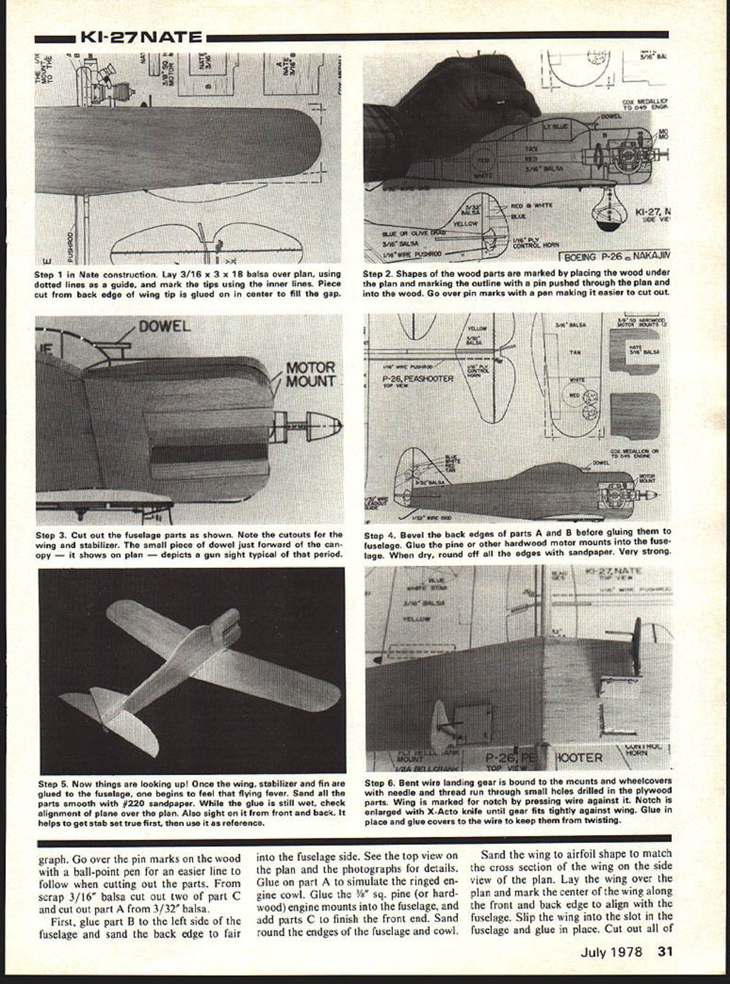
Step 1 in Nate construction. Lay 3/16" x 3" x 18" balsa over plan, using dotted lines as a guide, and mark the tips using the inner lines. Piece cut from back edge of wing tip is glued on in center to fill the gap.
Step 2. Shapes of the wood parts are marked by placing the wood under the plan and marking the outline with a pin pushed through the plan and into the wood. Go over pin marks with a pen making it easier to cut out.
Step 3. Cut out the fuselage parts as shown. Note the cutouts for the wing and stabilizer. The small piece of dowel just forward of the canopy — it shows on plan — depicts a gun sight typical of that period.
Step 4. Bevel the back edges of parts A and B before gluing them to fuselage. Glue the pine or other hardwood motor mounts into the fuselage. When dry, round off all the edges with sandpaper. Very strong.
Step 5. Now things are looking up! Once the wing, stabilizer and fin are glued to the fuselage, one begins to feel that flying fever. Sand all the parts smooth with #220 sandpaper. While the glue is still wet, check alignment of plane over the plan. Also sight it from front and back. It helps to get stab set true first, then use it as reference.
Step 6. Bent wire landing gear is bound to the mounts and wheelcovers with needle and thread run through small holes drilled in the plywood parts. Wing is marked for notch by pressing wire against it. Notch is enlarged with X-Acto knife until gear fits tightly against wing. Glue in place and glue covers to the wire to keep them from twisting.
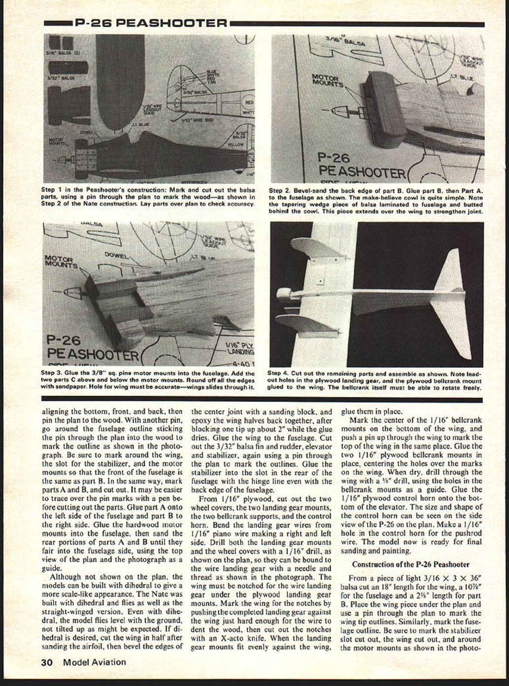
Go over the pin marks on the wood with a ball-point pen for an easier line to follow when cutting out the parts. From scrap 3/16" balsa cut out two of part C and cut out part A from 3/32" balsa.
First, glue part B to the left side of the fuselage and sand the back edge to fair into the fuselage side. See the top view on the plan and the photographs for details. Glue on part A to simulate the ringed engine cowl. Glue the 3/8" sq. pine (or hardwood) engine mounts into the fuselage, and add parts C to finish the front end. Sand round the edges of the fuselage and cowl.
Sand the wing to airfoil shape to match the cross section of the wing on the side view of the plan. Lay the wing over the plan and mark the center of the wing along the front and back edge to align with the fuselage. Slip the wing into the slot in the fuselage and glue in place. Cut out all of the tail parts from 3/32" balsa and glue the stabilizer into the slot in the fuselage. Glue the fin in place on top of the fuselage. Cut out the 1/16" plywood landing gears, tailskid, bellcrank mounts, and control horn. Drill a 1/16" hole in the control horn for the pushrod wire, and 1/8" holes in the bellcrank mounts and landing gears. Also, drill two holes in the right side landing gear for the control wires.
Glue the plywood landing gears to the wing and add 1/4" triangle on each side of each gear. Mark the bottom of the wing for the center of the bellcrank mounts, and push a pin through the wing on the mark to locate the same spot on the top of the wing.
Glue the plywood bellcrank mounts on the tip and bottom of the wing, centering the hole over the mark. Glue the plywood tail skid in place. Glue the plywood control horn to the bottom of the elevator. The P-26 is now ready for sanding and finishing.
Finishing the models: Shape and round the edges of the models, using #80 or #100 grit garnet, or aluminum oxide, sandpaper. Sand the edges of the elevator and all of the tail parts round, except for the rudder and fin hinge line—which are glued after painting. Finish sand the entire model with #220 garnet, or aluminum oxide, sandpaper in the direction of the wood grain until smooth.
Brush on one coat of clear dope over the entire model and tail parts, and allow to dry. Sand the entire model with #220 sandpaper until the wood feels smooth again. Brush on a second coat of clear and, when dry, sand smooth. A third coat of clear may be needed in some areas. Additional coats of a sanding sealer, or clear dope mixed with baby powder, can be applied if you want to fill the grain. Sand between coats.
The overall color of the Nate is pale gray, or greenish gray. Use Pactra Aerogloss Military Flats, hot-fuel-proof dope, Cloud Gray as the base color. Regular Aerogloss colors can be used if the Military Flats are not available, although the gray is a little too dark. One part of gray and two parts white would be close enough.
Many Nates were simply painted gray with the round red insignia on the wing and fuselage, but most had additional stripes or designs. The window is masked off with tape and painted light blue. Mask off the white bands and paint with Swift White. The nose and fuselage stripe is red dope, applied after first masking with tape. The best masking tape is Sig striping tape in 1/4" width, otherwise use plastic electrician's tape, or Scotch Tape.
P-26 Peashooters had bright yellow wings and tails, and either dark green or blue fuselages. First, paint the wings, fin, stab, and elevators with Aerogloss Cub Yellow, applying each successive coat in a different direction. Sand lightly with #220 sandpaper between each coat. (Cub Yellow is also available in spray cans as are all of the standard colors.) Allow the yellow to dry for several hours, then mask off at the fuselage junction. If spraying, the wings can each be covered with paper or paper bags and masking tape to protect from overspray. Paint the fuselage either Curtiss Blue or Stinson Green. Paint the separate rudder white.
The insignia and stripes are cut from either Monokote Trim sheets, or contact shelf paper. Contact paper is fuel-proof and inexpensive. It is easy to use and is ideal for masking complex shapes, which can be cut out first. Draw the stars by placing white trim under the plan and marking the star points with a pin through the plan. Connect the points with a pencil and cut out the stars. Stick the stars onto blue trim, draw the circles, and cut out. Apply small red circles in the center of the stars and stick the completed insignia onto the model. The blue stripe on the fin, and the red stripes on the rudder, are cut from trim sheets, then stuck on.
The lines and rivet dots on my models were applied with a #1 rapidograph drafting pen, and Pelikan drafting ink. This ink is water soluble and can be washed off if you make a mistake. Use a ruler with a raised edge to apply the lines. The dots are applied freehand.
I experimented with a black pentel rolling writer and it worked very well, much easier to use than a drafting pen. All lines and ink marks must be sealed with one or more spray coats of clear after the model is finished. Apply the first coat very lightly from a spray can to prevent the ink from bleeding. The Pentel pen bled much less than a Flair pen.
Assembly: Hinge the elevators to the stab with a large needle and carpet thread, using a "figure-8" stitch. Leave about 6" of thread at each end of each hinge until all are done, then using the needle as a pick, pull the threads until the hinge is tight. When all the thread hinges are tight, apply glue to both sides of the hinges and clip the loose ends flush with the wood.
Bend the 1/16" wire pushrod and attach to the control horn on the elevator. Cut the 1/32" wire leadout wires and attach to the bellcrank along with the pushrod. Bolt the bellcrank to the wing, keeping the entire linkage free from binding. Bend the wire leadout guide and glue to the wing.
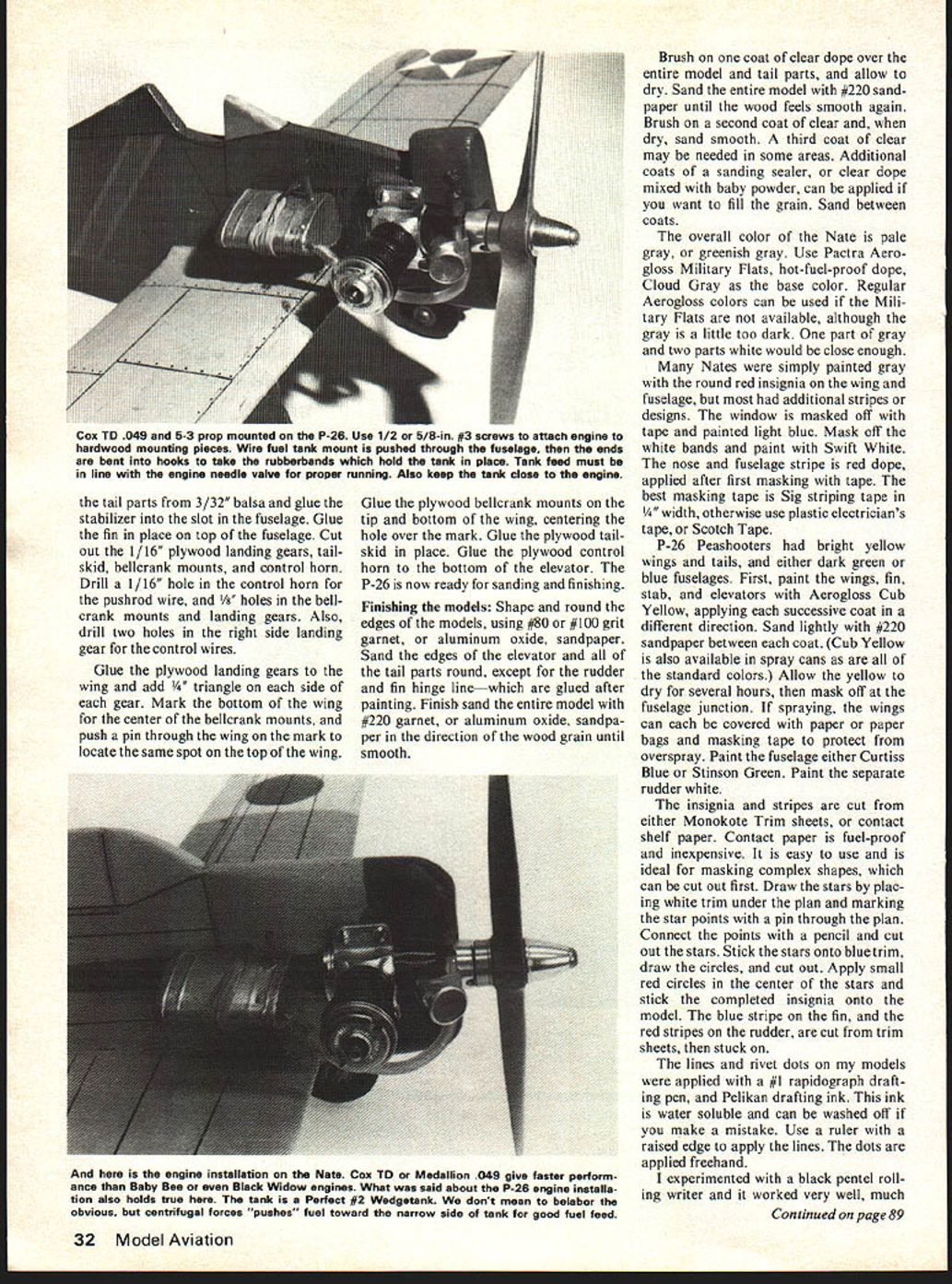
Pre drill the four mounting holes with a 1/16" drill, then mount the engine with four #2 1/2" wood screws. Drill two 1/16" holes through the fuselage for the tank mount wire. Slip the wire tank mount through the holes and bend the ends over to form hooks. Place the tank in place and secure with a rubberband. Drill a 5/32" hole up through the wing, directly under the fuel tank vent tube, then push a 1" length of fuel tubing up through the hole and over the vent tube. Glue two pennies to the underside of the outboard wing tip to help maintain line tension while flying. Enlarge the cutout in the rudder to clear the elevator if needed, then glue the rudder to the fin at the angle shown on the plan. Put on the wheels and you are ready to fly.
Flying: Use 26' x .008" wire lines for flying if possible, rather than the Dacron flying lines, for more positive control. Use a Cox .5 x 3 gray plastic prop, or a Cox .5 x 4 black plastic prop, and Cox Glow Fuel. The higher nitro content of Cox Racing Fuel will take off the paint.
Transcribed from original scans by AI. Minor OCR errors may remain.

