
Firebolt
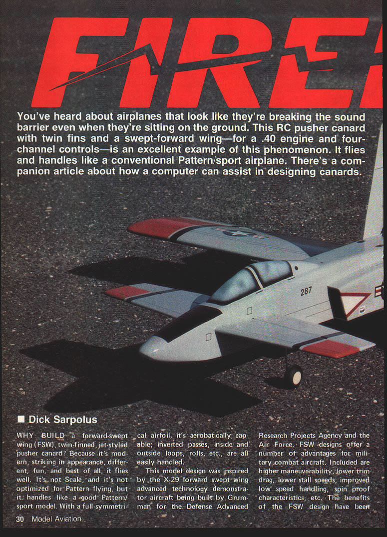
You've heard about airplanes that look like they're breaking the sound barrier even when they're sitting on the ground. This RC pusher canard with twin fins and a swept-forward wing—for a .40 engine and four-channel controls—is an excellent example of this phenomenon. It flies and handles like a conventional Pattern/sport airplane. There's a companion article about how a computer can assist in designing canards.
Dick Sarpolus
Why build this canard?
Why build a forward-swept wing (FSW), twin-finned, jet-styled pusher canard? Because it's modern, striking in appearance, different, fun, and best of all, it flies well. It's not scale, and it's not optimized for Pattern flying, but it handles like a good Pattern/sport model. With a full-symmetrical airfoil, it's aerobatically capable; inverted passes, inside and outside loops, rolls, etc., are all easily handled.
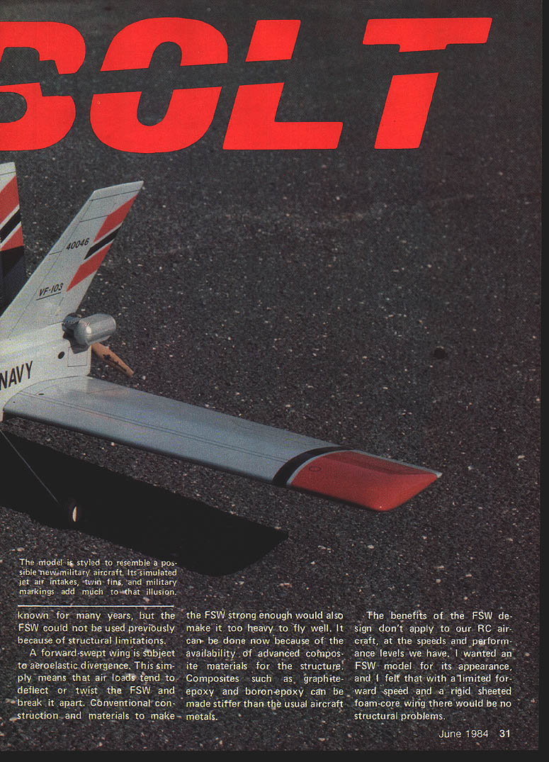
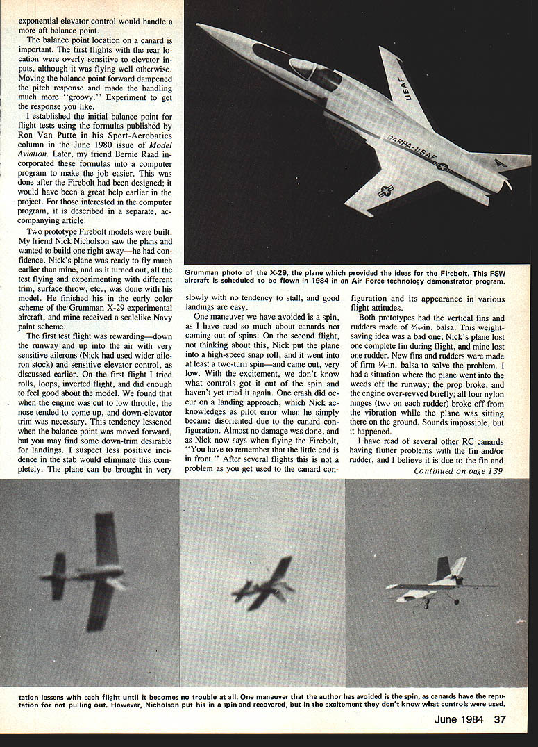
This model design was inspired by the X-29 forward-swept wing advanced technology demonstrator aircraft built by Grumman for DARPA and the Air Force. FSW designs offer advantages for full-scale combat aircraft—higher maneuverability, lower trim drag, lower stall speeds, improved low-speed handling, and spin-resistant characteristics. Historically, FSWs suffered from aeroelastic divergence (air loads tending to twist and overstress the wing), but modern composites make such designs feasible. For our RC speeds and construction, the practical benefits are limited; I wanted the FSW for appearance and felt that a rigid sheeted foam-core wing would avoid structural problems.
RC canard designs are becoming more common. A real breakthrough was the Zonker by Milt Sanders and Charlie Bair (Model Aviation, March 1977). Since then other canards have appeared in Flying Models, RC Modeler, and Model Aviation. Expect trainer versions, super-stable sport types, and Pattern designs in the future.
Canards have RC-specific benefits: the horizontal stabilizer produces lift like the wing, resulting in efficient lift-sharing between wing and stab. The lack of high-speed prop wash over the aircraft can decrease drag. In my experience flying the Firebolt at 7 lb., it handles like a much lighter model and appears faster than an equally powered conventional model. And, of course, there's no exhaust oil to wipe off.
Full-scale canard successes (Burt Rutan's Vari-Eze, Beech Starship, Gates-Piaggio GP-180) demonstrate the layout's viability. I've built canards before—control-line and RC sailplane designs—which led me to try an FSW version.
Design summary
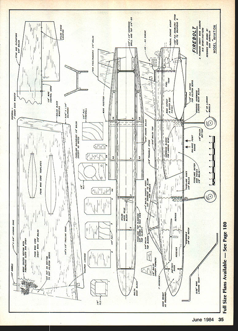
The Firebolt owes much to the Sanders-Bair Zonker. Key design data:
- Wing span: 57 in.
- Wing area: 580 sq. in.
- Planform: tapered from an 11½-in. root to a 9-in. tip
- Thickness: 16% root to 17% tip
- Airfoil: full-symmetrical
- Leading edge: swept forward with the tip 4 in. ahead of the root
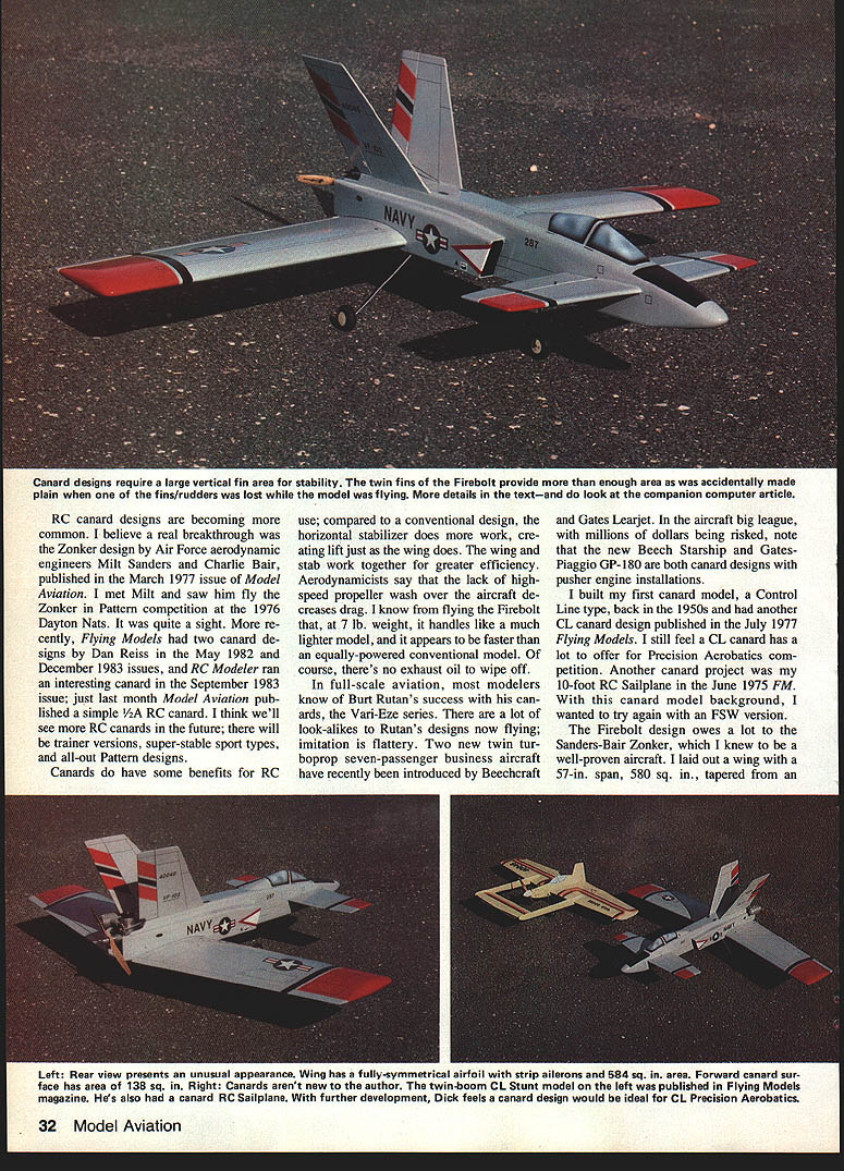
- Horizontal stabilizer area: 138 sq. in. (23% of wing area)
- Twin vertical fins total area: 145 sq. in. (25% of wing area) — more than necessary; the model will fly with only one fin if you prefer that styling
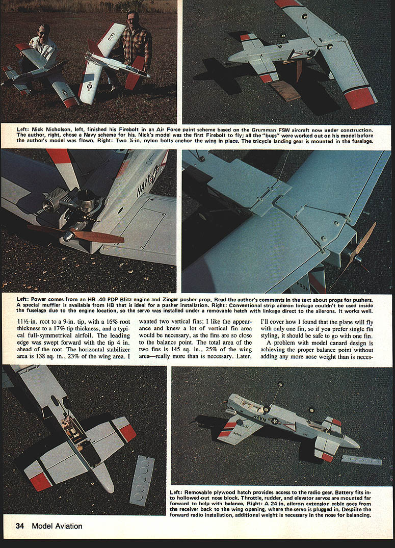
A design challenge for canards is obtaining the proper balance point without adding excessive nose weight. I located the engine above the wing trailing edge, installed radio gear far forward, and put the landing gear in the fuselage. Even so, about 10–12 oz. of lead was required in the nose. You can reduce nose ballast by keeping the wing light and using a light engine/muffler. Note that a forward-swept wing requires a balance point location farther forward than a straight or swept-back wing.
Conversations with foam-wing expert Bob Hunt convinced me that attaching balsa wing sheeting with epoxy would be lighter than contact cement, and that plastic film covering would save additional weight. The Firebolt flies well at 7 lb., but saving rear weight helps avoid carrying lead in the nose.
Powerplant and prop
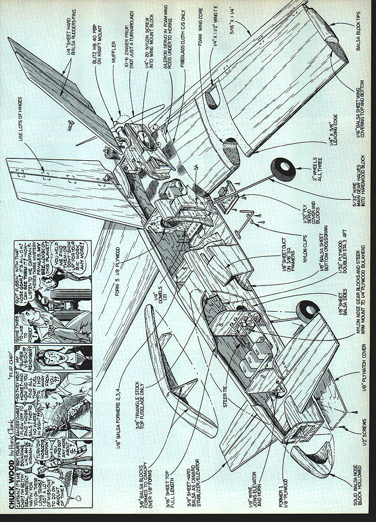
The engine used is an HB .40 PDP Blitz, run with a 10x6 Zinger pusher prop. HB offers a special short muffler to clear the prop in the pusher configuration; I used the muffler spacer on my Firebolt. The HB .40 required a .60-size engine mount; I used a molded Kraft unit.
Pusher props are now available from several manufacturers; Zinger has a full line and good quality. Note: a right-hand (clockwise) pusher prop is necessary. You cannot simply mount a conventional prop backwards unless the engine has been converted to run clockwise. Many engines can be converted by a reverse-ported crankshaft, but using a dedicated pusher prop is easier. In a pusher or tractor installation the front curved surface of the prop faces forward in the direction of flight.
Balance point and trimming
A balance point range is shown on the plans for the model without fuel in the tank. The Firebolt has been flown at forward, aft, and intermediate locations. I suggest starting at the forward location and then moving aft to suit your preference. Pitch response changes with the balance point; elevator throw also affects response. Radios with exponential elevator control will better handle a more-aft balance point.
Initial balance calculations used formulas published by Ron Van Putte (Sport-Aerobatics, Model Aviation, June 1980). Bernie Raad later incorporated these into a computer program to simplify the job.
First flights with a rear balance location were overly sensitive to elevator inputs; moving the balance point forward dampened pitch response and made handling more comfortable. Experiment to achieve the response you like.
Flight testing and experience
Two prototype Firebolts were built. Nick Nicholson finished his first and did most of the test flying. His model wore an early Grumman X-29 color scheme; mine received a scale-like Navy paint scheme.
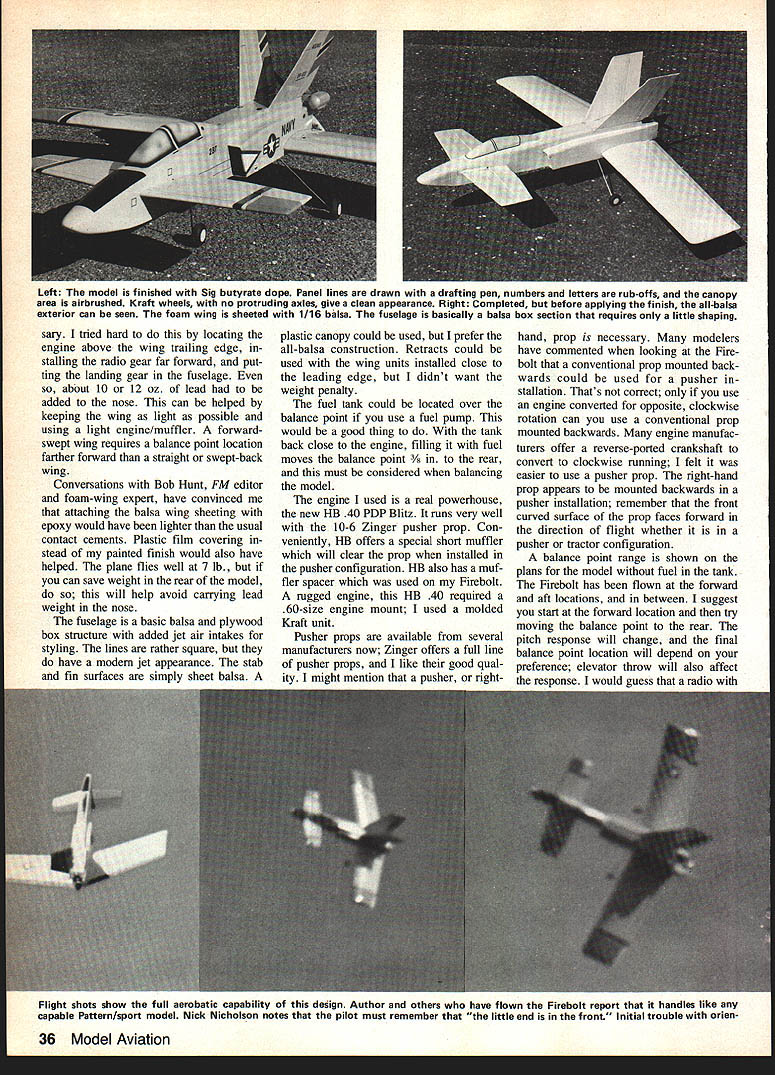
The first test flight: down the runway and up into the air with very sensitive ailerons (Nick used wider ailerons) and sensitive elevator control. Rolls, loops, and inverted flight were handled easily. On low throttle the nose tends to come up, and down-elevator trim may be necessary; this tendency lessened when the balance point was moved forward. The plane can be brought in slowly with no tendency to stall, and good landings are easy.
We avoided intentional spins because of canard spin concerns. On one flight, a high-speed snap-roll resulted in at least a two-turn spin; it recovered very low. We don't know exactly which controls recovered it. One landing-approach crash occurred from pilot disorientation—almost no damage resulted. After several flights you get used to the configuration and the appearance in different flight attitudes. As Nick says: "You have to remember that the little end is in front."
Early prototypes used 1/16-in. balsa for the vertical fins and rudders to save weight—this was a mistake. Nick lost one fin in flight; my model later lost the other rudder. Replacing them with 1/8-in. balsa solved the problem. I recommend using firm 1/4-in. balsa for the fins and rudders and plenty of hinges, as the fins are close to the engine and subject to vibration. We've had no further trouble after beefing them up. Nick's Firebolt handled okay on a dead-engine landing even after one fin had broken off, so one fin provides sufficient vertical area in a pinch.
Lance Schneider (an accomplished local RC pilot) flew the Firebolt and reported it handled very well—more like a good Pattern ship than expected. He found it stable, especially on landings. I'm planning another canard design directed more toward Pattern performance.
Construction notes
The Firebolt structure is simple and can be built quickly. I prefer cutting all necessary parts before assembly and preparing a personal kit. If you don't have a local source, Lou Wolgast, 40 Castlewood Trail, Sparta, NJ 07871, is listed as a parts source.
Wing
- The wing is skinned with 5/16 balsa. Apply the balsa skin with slow-curing epoxy for the lightest, strongest bond.
- Edge-glue 1/16 balsa to the spar to fair the wing skins and lightly sand for a good fit.
- Spread epoxy on the underside of the balsa skin, place it on the foam core, then put the skinned core back on the board and weight it until cured.
- Promptly apply the top skin, add the top foam block section over the sheeted wing, and hold everything in place with plenty of weight until cured.
- The next day, trim the sheeting flush with the core, add and shape leading and trailing edge stock, add balsa tip blocks, and epoxy the wing halves together at the proper dihedral angle.
- Reinforce the center-section joint with heavy fiberglass cloth and epoxy.
- Standard strip aileron linkage can be used, or bolt nylon horns on the inboard ends. A small removable hatch over the servo can reduce clutter; alternatively, install the servo and bellcranks inside the foam core.
Fuselage
- Start by gluing plywood doublers and triangle stock to the side pieces, then join the sides with bulkheads. Sides are parallel from the firewall to the second bulkhead for easy alignment.
- Add outer bulkheads and 1/16 balsa strips to accept the outer fuselage sides, then add the fuselage top back to the double-fin location.
- Tack-glue, rough-shape, remove, and hollow the nose block for nose weight and battery pack, then glue it in place for final shaping.
- The horizontal stabilizer (3/8 balsa) is glued in place; insert the wire elevator horn before installing the stabilizer.
- Cut and sand the fuselage inner top edges to position the twin fins at the proper angle; epoxy the fins in place, then finish the fuselage top planking between them.
- Epoxy a piece of 3/8 x 3/4 hardwood, grooved to accept two 5/32-in. wire landing gears side-by-side, across the fuselage bottom just ahead of the wing opening. Glue vertical hardwood pieces inside the fuselage to take the landing gear ends.
- Before adding the fuselage bottom planking, cut necessary holes in bulkheads and install the two nylon-tubing control linkages to the rudders and the flexible throttle cable linkage through the firewall. Provide a feed-through for the aileron servo extension cable.
- Drill and tap hardwood pieces for the two 1/4-20 nylon wing mounting bolts. The forward radio-compartment hatch (1/8 plywood) is held with six 1/4 x 1/2-in. screws into small hardwood blocks.
- Assemble and shape the balsa sheeting before gluing it to the fuselage top.
Fuel system and engine installation
- I used a Kraft molded engine mount and a Sullivan SS-8 fuel tank. The tank is positioned ahead of the firewall (same direction as a conventional model). Bend fuel and vent lines back over the top of the tank and run them back through the firewall to the engine. The long lines did not cause problems; the engine runs fine through all maneuvers.
- We used muffler pressure to the tank vent. The HB muffler exhausts directly to the rear; on Nick's Firebolt a long conventional muffler pointed forward caused exhaust mess. He plugged the exhaust, drilled a same-size hole in the front end of the muffler and pointed it to the rear—this worked fine.
Finishing
- Plastic film covering is the lightest finishing method. Nick MonoKoted his wing and tail surfaces and painted the fuselage with Hobbypoxy. I painted my Firebolt with Sig butyrate dope.
- For a butyrate paint job base, I prefer Sig-Skinner Coverite for wing and tail surfaces—easy to apply, permanent, and easy to fill. I often use only Sig sanding sealer on the fuselage as a base.
Construction tip for balsa sheeting with epoxy
- Use slow-curing epoxy (warm water can improve flow). Spread epoxy lightly on the wood, place the skin on the core, then place the skinned core back on the board and weight it until cured. Promptly apply the top skin and the top foam block, and weight the assembly until set.
Suggested control throws
As measured at the trailing edge of the surfaces:
- Aileron: about 1/4 in. each way
- Elevator: about 5/8 in. each way
- Rudder: about 3/4 in. each way
Adjust surface movement to suit your flying style.
Flying tips and handling notes
- Remember: the little end is in front.
- Don't pull the plane off the ground too quickly. Too much rotation might cause prop to strike the ground (we never had this problem), and controls are ineffective until flying speed is reached.
- There is no prop blast over the control surfaces, so forward speed is needed for control authority. If you slow way down and then apply high throttle, the elevator may not be effective until some airspeed is regained—apply throttle gradually on a go-around.
- Landings are easy—the plane settles in slowly, nose high, and is very stable on approach.
- Wingovers look good; use rudder before all airspeed is gone because there is no prop blast helping the rudders.
- Snap maneuvers and spins: proceed cautiously. If you experiment and change the design, calculate the balance point carefully—do not fly tail-heavy.
- Keep plenty of vertical fin area. A ducted-fan version of the Firebolt would be interesting; with the fan mounted in the fuselage above the wing, achieving the correct balance point would be easier.
Have fun flying tail first!
Transcribed from original scans by AI. Minor OCR errors may remain.

