

Fixed-geometry model for 1/2A‑F1J has a winning pedigree: "Evolution, not revolution"
Jean G. Paillet
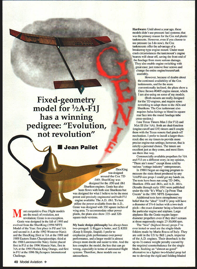
Most competitive free‑flight models are the result of evolution, not revolution; Genie is no exception. Genie was designed in the fall of 1995 and evolved from the Shuriken (1994 NFFS Model of the Year; first place in F1J and 1/2A) and the ShockKing (first in 1/2A at the 1988 and 1989 Eastern States Championships; third at the 1988 Lawrenceville Nats). Genie placed first in F1J at the 1996 Muncie Nats, first in 1/2A at the 1995 Florida King Orange, and first in F1J at the 1996 SkyScrapers International Challenge.
My basic design philosophy has always been two‑pronged:
- Bigger is better.
- KISS (Keep It Simple, Stupid).
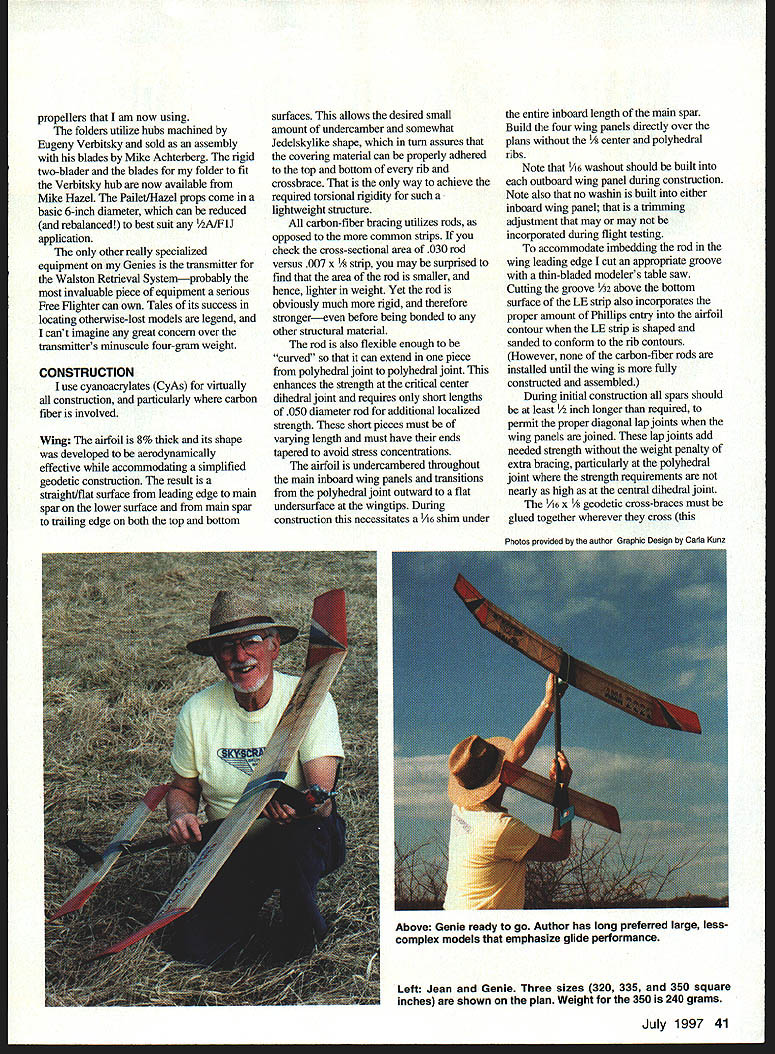
I prefer to emphasize glide performance over power performance. A larger model is almost always more docile and easier to trim. And the less complex the model, the less that can go wrong, especially in terms of automated flight systems. Therefore, these models use no autosurfaces.
Hardware
Until about a year ago, these models didn't use pressure fuel systems; that was the primary reason for the Cox red plastic tankmounts. However, even if you choose to use pressure (as I do now), the Cox tankmounts offer the advantage of a breakaway type engine mount. Under most crash circumstances the tankmount's engine bearers will shear off, saving the front end of the fuselage from more serious damage. They also enable engine switching with great ease; just remove four screws and change the entire engine/mount/tank assembly.
Because of doubts about the continued availability of the Cox tankmounts, and for the more conventionally inclined, the plans show a Dave Brown #0405 engine mount, which I am also using on some of my models.
(Both mounts are really designed for the TD engines and require some reworking to adapt them to the A.D. engines and Shurikens. The Cox tankmount also requires balsa fairings to blend its square rear face into the round fuselage tube cross‑section.)
I use Texas Timers Max I (for F1J) and Max III (for 1/2A). Both are dual‑function (engine cutoff and DT) timers and I couple them with the Texas remote fuel pinch‑off mechanism. I prefer to install a larger‑than‑stock disc on my timers to provide more precise engine‑run settings; however, that is strictly a personal choice. The timers are excellent as supplied, and most fliers use them that way.
Commercially available propellers for 1/2A and F1J are a different story; in my opinion, "There ain't none!" except those sold by various cottage‑industry entrepreneurs.
In 1988 I began an ongoing program to measure the static thrust produced by any 1/2A/F1J‑size props I could get my hands on. The tests have been run using TD .049s, Shuriken .050s and .061s, and A.D. .061s. Results through early 1991 were published under the title "It's What's Up Front That Counts" in the 1991 NFFS Symposium. Additional tests have strengthened my belief that the "ideal" 1/2A/F1J prop will have a diameter of 5 3/4–6 inches with a two‑inch pitch—the exact diameter being a function of the particular engine and airplane.
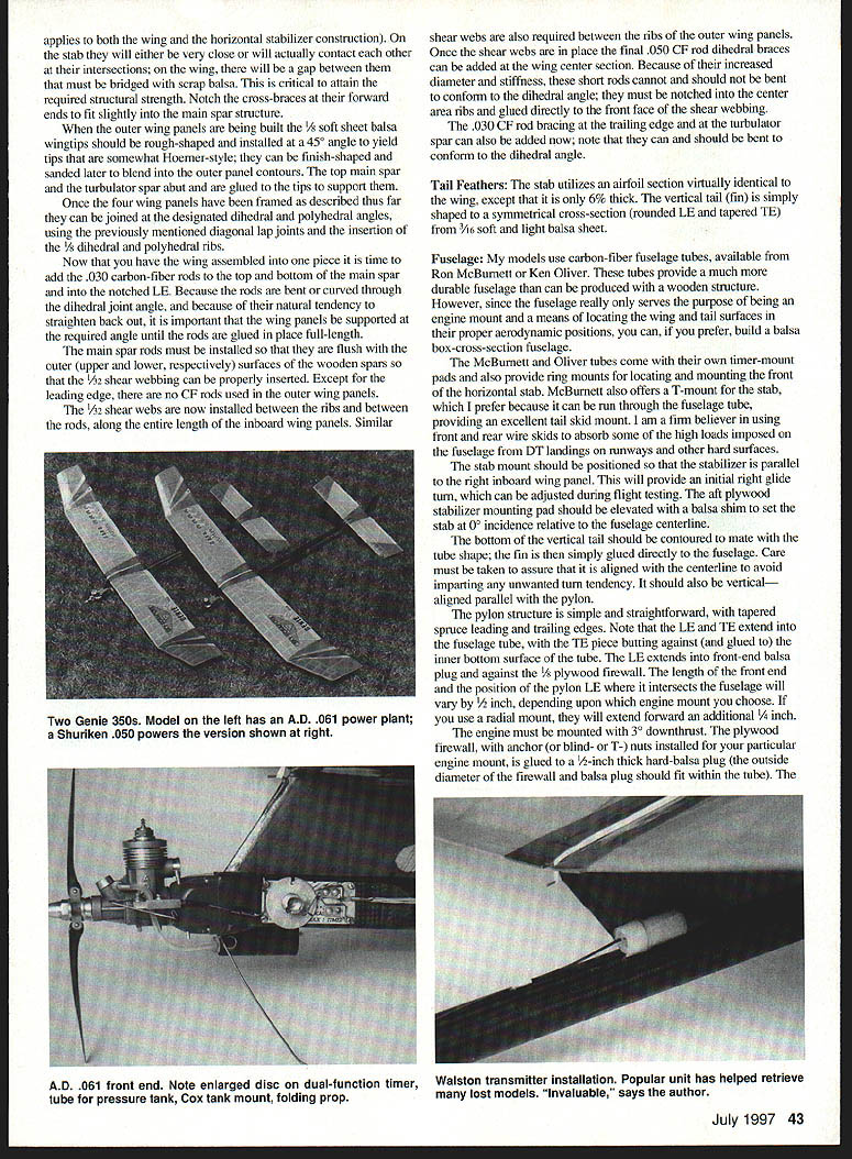
Large airplanes like the Genie require larger‑diameter propellers even if they don't scream; the "best" (highest thrust) props I've ever tested were single‑blade folders made by Mario Rocca of Italy and sold in the U.S. by Bill Lynch, importer of the A.D. engines. Their drawback is the up‑to‑1/2‑ounce weight penalty caused by the required counterbalance. Seeking an almost‑as‑good alternative, a lighter two‑bladed prop led me to develop the rigid and folding‑bladed props I am now using. The folders utilize hubs machined by Eugeny Verbitsky and sold assembled with blades by Mike Achterberg. Rigid two‑blader blades and folders that fit the Verbitsky hub are now available from Mike Hazel. Paillet/Hazel props come in a basic 6‑inch diameter that can be reduced and rebalanced to best suit the 1/2A/F1J application.
Other really specialized equipment: Genie's transmitter‑mounted Walston Retrieval System is probably the most invaluable piece of equipment a serious Free Righter can own. Tales of its success locating otherwise‑lost models are legend. I can't imagine anyone having great concern over transmitters' minuscule four‑gram weight.
Construction
I use cyanoacrylates (CyAs) for virtually all construction, particularly where carbon fiber is involved.
Wing airfoil and structure
- Airfoil: 8% thick. Its shape was developed to be aerodynamically effective while accommodating a simplified geodetic construction method.
- The construction results in straight/flat surfaces at key locations—leading edge strip, main spar lower surface, and main spar trailing edge—which simplifies building and ensures good adhesion of covering material.
- This approach allows the desired small amount of undercamber and a consistent airfoil shape, which in turn assures that the covering material can be properly adhered to the top and bottom of every rib and crossbrace. That is the only way to achieve the required torsional rigidity for such a lightweight structure.
All carbon‑fiber bracing utilizes rods, as opposed to the more common strips. If you check the cross‑sectional area of a .030 rod versus a .007 x 1/8 strip, you may be surprised to find that the area of the rod is smaller, and hence lighter in weight. Yet the rod is much more rigid, and therefore stronger—even before being bonded to any other structural material.
The rod is also flexible enough to be curved so that it can extend in one piece from polyhedral joint to polyhedral joint. This enhances the strength at the critical center dihedral joint and requires only short lengths of .050‑diameter rod for additional localized strength. These short pieces must be of varying length and must have their ends tapered to avoid stress concentrations.
The airfoil is undercambered throughout the main inboard wing panels and transitions from the polyhedral joint outward to a flat undersurface at the wingtips. During construction this necessitates a 1/16" shim under the entire inboard length of the main spar. Build the four wing panels directly over the plans without the 1/2 center and polyhedral ribs.
Note that 1/16" washout should be built into each outboard wing panel during construction. No washin is built into either inboard wing panel; washin is a trimming adjustment that may or may not be incorporated during flight testing.
To accommodate embedding the rod in the wing leading edge, cut an appropriate groove with a thin‑bladed modeler's table saw. Cutting the groove 1/32" above the bottom surface of the LE strip also incorporates the proper amount of shaping into the airfoil contour when the LE strip is shaped and sanded to conform to the rib contours. (None of the carbon‑fiber rods are installed until the wing is more fully constructed and assembled.)
During initial construction all spars should be at least 1/2" longer than required, to permit the proper diagonal lap joints when the wing panels are joined. These lap joints add needed strength without the weight penalty of extra bracing, particularly at the polyhedral joint where the strength requirements are not nearly as high as at the central dihedral joint.
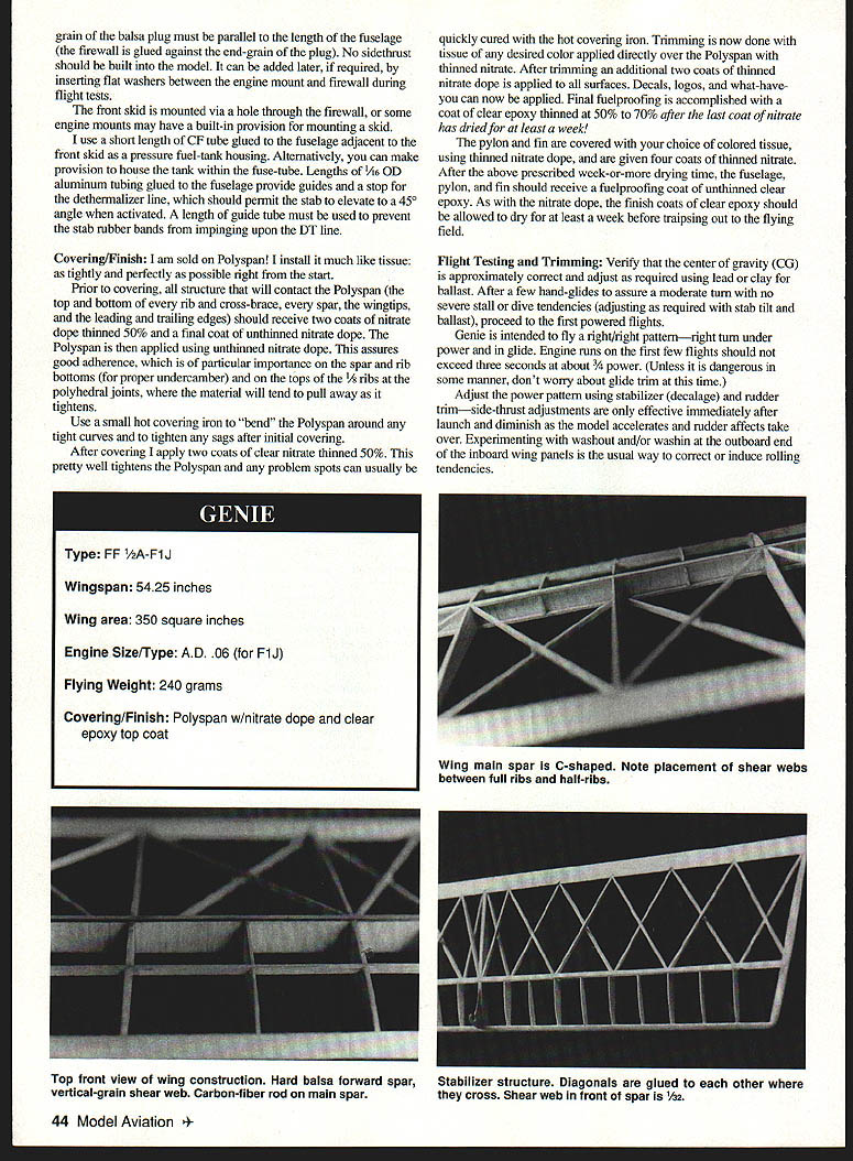
The 1/16" x 1/8" geodetic cross‑braces must be glued together wherever they cross (this adds shear webbing at rib stations). This applies to both the wing and the horizontal stabilizer construction. On the stab they will either be very close or will actually contact each other at their intersections; on the wing, there will be a gap between them that must be bridged with scrap balsa. This is critical to attain the required structural strength. Note the cross‑braces at their forward ends to fit slightly into the main spar structure.
When the outer wing panels are being built the 1/8" soft sheet balsa wingtips should be rough‑shaped and installed at a 45° angle to yield tips that are somewhat horn‑shaped; they can be finish‑shaped and sanded later to blend into the outer panel contours. The top main spar and the turbulator spar are glued to the tips to support them.
Once the four wing panels have been framed as described, they can be joined at the designated dihedral and polyhedral angles, using the previously mentioned diagonal lap joints and the insertion of the 1/8" dihedral and polyhedral ribs.
Now that the wing is assembled into one piece it is time to add the .030" carbon‑fiber rods to the top and bottom of the main spar and into the notched leading edge. Because the rods are bent or curved through the dihedral joint angle, and because of their natural tendency to straighten back out, it is important that the wing panels be supported at the required angle until the rods are glued in place full‑length.
The main spar rods must be installed so that they are flush with the outer (upper and lower, respectively) surfaces of the wooden spars so that the 1/32" shear webbing can be properly inserted. Except for the leading edge, there are no CF rods used in the outer wing panels.
The 1/32" shear webbing is now installed between the ribs and between the rods, along the entire length of the inboard wing panels. Similar shear webs are also required between the ribs of the outer wing panels. Once the shear webs are in place the final .050" CF rod dihedral braces can be added at the wing center section. Because of their increased diameter and stiffness, these short rods cannot and should not be bent to conform to the dihedral angle; they must be notched into the center area ribs and glued directly to the front face of the shear webbing.
The .030" CF rod bracing at the trailing edge and at the turbulator spar can also be added now; note that they can and should be bent to conform to the dihedral angle.
Tail feathers
- Stabilizer: Uses an airfoil section virtually identical to the wing, except that it is only 6% thick.
- Fin: The vertical tail (fin) is simply shaped to a symmetrical cross‑section (rounded leading edge and tapered trailing edge) from 3/16" soft and light balsa sheet.
Fuselage
My models use carbon‑fiber fuselage tubes, available from Ron McBurnett or Ken Oliver. These tubes provide a much more durable fuselage than can be produced with a wooden structure. However, since the fuselage really only serves the purpose of being an engine mount and a means of locating the wing and tail surfaces in their proper aerodynamic positions, you can, if you prefer, build a balsa box‑cross‑section fuselage.
The McBurnett and Oliver tubes come with their own timer‑mount pads and also provide ring mounts for locating and mounting the front of the horizontal stab. McBurnett also offers a T‑mount for the stab, which I prefer because it can be run through the fuselage tube, providing an excellent tail‑skid mount. I am a firm believer in using front and rear wire skids to absorb some of the high loads imposed on the fuselage from DT landings on runways and other hard surfaces.
The stab mount should be positioned so that the stabilizer is parallel to the right inboard wing panel. This will provide an initial right‑glide trim, which can be adjusted during flight testing. The aft plywood stabilizer mounting pad should be elevated with a balsa shim to set the stab at 0° incidence relative to the fuselage centerline.
The bottom of the vertical tail should be contoured to mate with the tube shape; the fin is then simply glued directly to the fuselage. Care must be taken to assure that it is aligned with the centerline to avoid imparting any unwanted turn tendency. It should also be vertical—aligned parallel with the pylon.
The pylon structure is simple and straightforward, with tapered spruce leading and trailing edges. Note that the LE and TE extend into the fuselage tube, with the TE piece butting against (and glued to) the inner bottom surface of the tube. The LE extends into the front‑end balsa plug and against the 1/8" plywood firewall. The length of the front end and the position of the pylon LE where it intersects the fuselage will vary by 1/2" depending upon which engine mount you choose. If you use a radial mount, it will extend forward an additional 1/4".
The engine must be mounted with 3° downthrust. The plywood firewall, with anchor (or blind or T) nuts installed for your particular engine mount, is glued to a 1/2" thick hard‑balsa plug (the outside diameter of the firewall and balsa plug should fit within the tube). The front skid is mounted via a hole through the firewall, or some engine noses may have a built‑in provision for mounting a skid.
I use a short length of CF tube glued to the fuselage adjacent to the front skid as a pressure fuel‑tank housing. Alternatively, you can make provision to house the tank within the fuse‑tube. Lengths of 1/16" OD aluminum tubing glued to the fuselage provide guides and a stop for the dethermalizer line, which should permit the stab to elevate to a 45° angle when activated. A length of guide tube must be used to prevent the stab rubber bands from impinging upon the DT line.
Covering/Finish
I am sold on Polyspan! I install it much like tissue: as tightly and perfectly as possible right from the start.
Prior to covering, all structure that will contact the Polyspan (the top and bottom of every rib and cross‑brace, every spar, the wingtips, and the leading and trailing edges) should receive two coats of nitrate dope thinned 50% and a final coat of unthinned nitrate dope. The Polyspan is then applied using unthinned nitrate dope. This assures good adherence, which is of particular importance on the spar and rib bottoms (for proper undercamber) and on the tops of the 1/8" ribs at the polyhedral joints, where the material will tend to pull away as it tightens.
Use a small hot covering iron to "bend" the Polyspan around any tight curves and to tighten any sags after initial covering.
After covering apply two coats of clear nitrate thinned 50%. This will further tighten the Polyspan; any problem spots can usually be quickly cured with the hot covering iron. Trimming is now done with tissue of any desired color applied directly over the Polyspan with thinned nitrate. After trimming an additional two coats of thinned nitrate dope are applied to all surfaces. Decals, logos, and the like can now be applied. Final fuelproofing is accomplished with a coat of clear epoxy thinned 50% to 70% after the last coat of nitrate has dried for at least a week.
The pylon and fin are covered with colored tissue using thinned nitrate dope, and are given four coats of thinned nitrate. After the week‑or‑more drying time, the fuselage, pylon, and fin should receive a fuelproofing coat of unthinned clear epoxy. Allow the epoxy finish coats to dry for at least a week before flying.
Flight testing and trimming
Verify that the center of gravity (CG) is approximately correct and adjust as required using lead or clay for ballast. After a few hand‑glides to assure a moderate turn with no severe stall or dive tendencies (adjusting as required with stab tilt and ballast), proceed to the first powered flights.
Genie is intended to fly a right/right pattern—right turn under power and in glide. Engine runs on the first few flights should not exceed three seconds at about 3/4 power. (Unless it is dangerous in some manner, don't worry about glide trim at this time.)
Adjust the power pattern using stabilizer (decalage) and rudder trim—side‑thrust adjustments are only effective immediately after launch; as the model accelerates the rudder's effect takes over. Experimenting with washout and/or washin at the outboard end of the inboard wing panels is the usual way to correct or induce rolling tendencies.
I prefer washout to washin because the drag created by any significant amount of washin can create a turning effect that overpowers the intended rolling effect. Drag and turning effects from washin usually act in concert with the intended rolling effect.
As the flights progress, gradually tune the engine to full power and increase the run duration to the maximum (generally seven seconds here in the East and Midwest). The final power pattern should be a very steep climb (almost vertical) with about 3/4 turn from launch to engine cutoff and subsequent transition into the glide pattern.
During the power‑pattern adjustment use a "quick DT" anywhere from one to ten seconds after engine cutoff. As you become more secure in the safety and perfection of the power pattern, you can begin to extend the glide duration. The more closely you observe the glide pattern, the more the small circle with a slow, flat, almost‑stalled glide attitude is the goal.
Adjustments here should primarily center on stab‑lift changes for turn and ballasting for CG changes to attain that ideal almost‑stalled glide. Any tendency to spiral with an outboard‑wing‑high/inboard‑wing‑low attitude in the turn may require washin and/or washout adjustments. They must be done with caution, as they will likely affect the power pattern as well.
Now begins the fine‑tuning, tweaking, and compromising of adjustments to obtain the optimum balance between the powered‑ and gliding‑flight cycles.
Now that the Genie is out of the bottle, it is up to you to master it so that it fulfills your wishes as it has mine.
Genie's success, and that of its predecessors, is not mine alone to claim; I had lots of help along the way. Many other avid free‑flighters counseled and cajoled, helped and hollered, advised and admonished me in my attempts to create airworthy aircraft. Thanks, and a share of the credit, to them.
Jean G. Paillet 30 Emerson Road Brookville, NY 11545
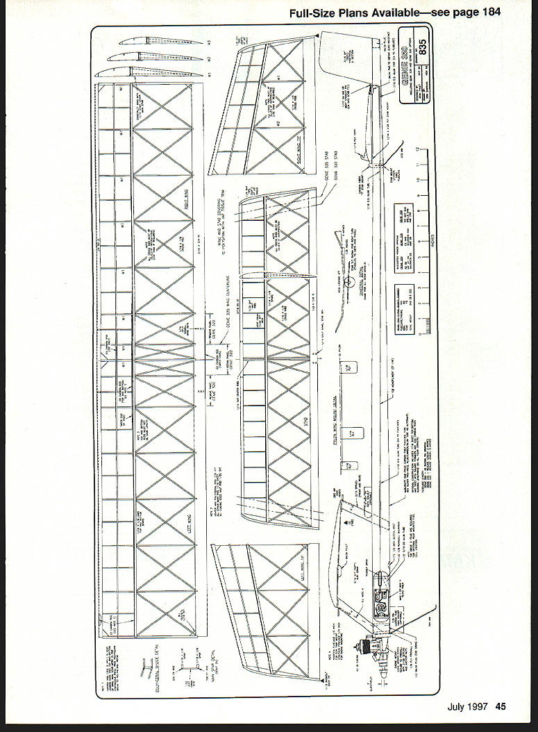
GENIE (specifications)
- Type: FF 1/2A‑F1J
- Wingspan: 54.25 inches
- Wing area: 350 square inches
- Engine size/type: A.D. .06 (for F1J)
- Flying weight: 240 grams
- Covering/finish: Polyspan with nitrate dope and clear epoxy top coat
Sources
- AD Engines, Rocca Props, Misc.:
Bill Lynch 11137 Creekhaven Court Auburn, CA 95602
- Texas Timers, Fuel Cutoffs:
Hank Nystrom 3317 Pine Timbers Drive Johnson City, TN 37604
- Paillet/Hazel Props:
Mike Hazel 1073 Windemere Drive Northwest Salem, OR 97304
- Polyspan, Covering Video:
Larry Davidson 1 Salisbury Drive East Northport, NY 11731
- Polyspan, Free‑Flight Supplies:
Starline International 6146 East Cactus Wren Road Scottsdale, AZ 85253
- Retrieval Systems:
Jim Walston 725 Cooper Lake Road Southeast Smyrna, GA 30082
- Carbon Fiber Rods, Etc.:
Aerospace Composite Products 14210 Doolittle Drive San Leandro, CA 94577
- Verbitsky Folding Props:
Mike Achterberg 3246 Seal Court Sacramento, CA 95827
- Engine Mounts:
Dave Brown Products 4560 Layhigh Road Hamilton, OH 45013
- Cox:
1295 H Street Penrose, CO 81240
- Fuselage Tubes:
Ron McBurnett 2265 Greenwood Road Rickreall, OR 97371
Ken Oliver 2213 El Cejo Circle Rancho Cordova, CA 95670
(Note: This scanned page contained only the full‑size plan drawings for the Genie model and did not include any additional continuing article text.)
Transcribed from original scans by AI. Minor OCR errors may remain.

