
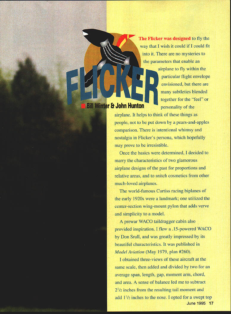
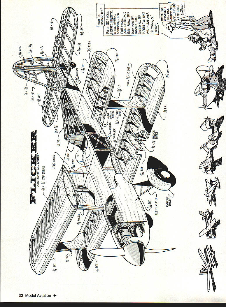
Flicker
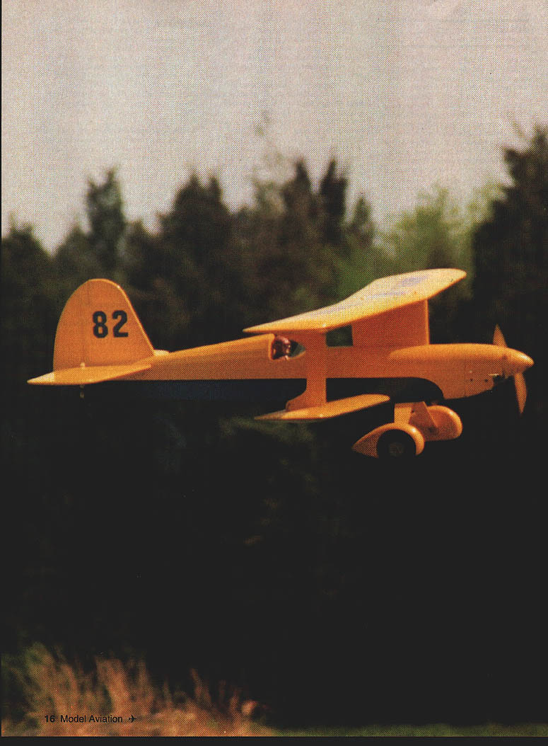
The Flicker was designed to fly the way I wish it could if I could fit into it. There are no mysteries to the parameters that enable an airplane to fly within the particular flight envelope envisioned, but there are many subtleties blended together for the "feel" or personality of the airplane. It helps to think of these things as people, not to be reduced to a pears-and-apples comparison. There is intentional whimsy and nostalgia in Flicker's persona, which hopefully may prove irresistible.
Once the basics were determined, I decided to marry the characteristics of two glamorous airplane designs of the past for proportions and relative areas, and to borrow cosmetics from other much-loved airplanes.
The world-famous Curtiss racing biplanes of the early 1920s were a landmark; one utilized the center-section wing-mount pylon that adds verve and simplicity to a model. A prewar WACO taildragger cabin also provided inspiration. I flew a .15-powered WACO by Don Srull and was greatly impressed by its beautiful characteristics (Model Aviation, May 1979, plan #260).
I obtained three-views of these aircraft at the same scale, then averaged them to determine span, length, gap, moment arm, chord, and area. A sense of balance led me to subtract 2-1/2 inches from the resulting tail moment and add 1-1/2 inches to the nose. I opted for a swept top wing — a Great Lakes/Curtiss/Seahawk touch of sweep — which improves both appearance and performance.
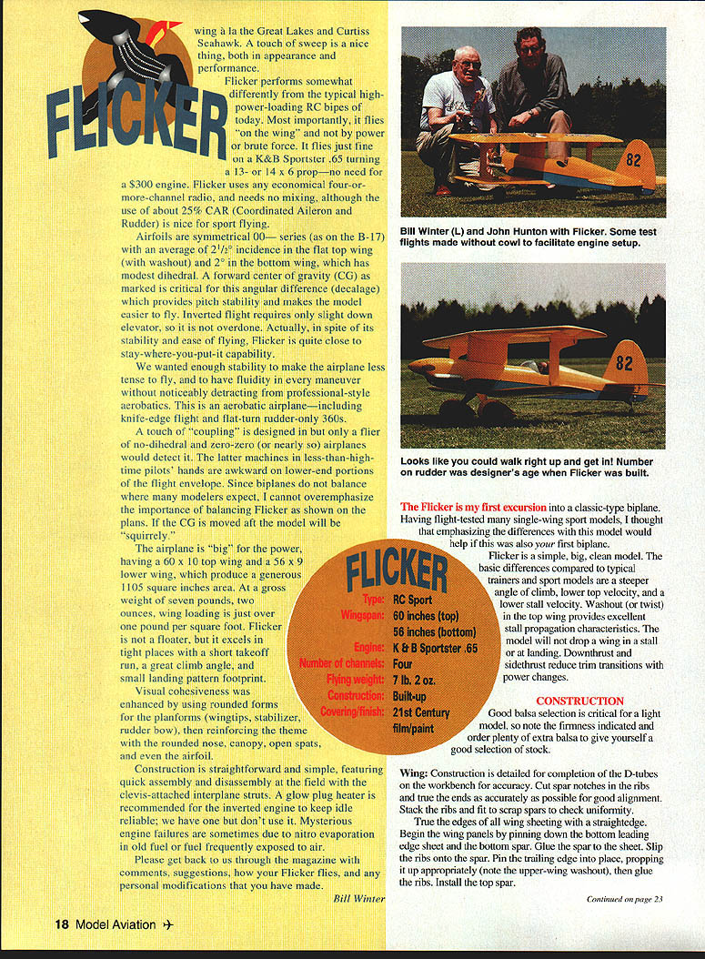
Flicker performs somewhat differently than typical high-power-loading RC bipes today. Most importantly, it flies on wing and power rather than brute force — it flies just fine on a K&B Sportster .65 turning a 13–14 x 6 prop; no need for a $300 engine. Flicker uses an economical four-or-more-channel radio and needs no mixing, although I use about 25% CAR (coordinated aileron/rudder) for nice sport flying.
Airfoils are symmetrical .00-series (B-17). Average incidence is +2° (top and bottom). The flat top wing has 2° washout; the bottom wing has modest dihedral. Forward center of gravity (CG) is marked. The critical angular difference (decalage) provides pitch stability and makes the model easier to fly. Inverted flight requires slight down elevator—not overdone. Despite its stability and ease of flying, Flicker is close to the "stay-where-you-put-it" capability I wanted: enough stability to make the airplane less tense to fly yet enough agility for professional-style aerobatics. It is an aerobatic airplane, including knife-edge flight, flat turns, and rudder-only 360s with a touch of coupling designed for the flier.
No dihedral (zero/zero) would be nearly undetectable; machines with less dihedral are more demanding on less-than-high-time pilots' hands, particularly in the lower-end portions of the flight envelope.
Since biplanes balance differently than many modelers expect, I cannot overemphasize the importance of balancing. If Flicker is built with the CG moved aft the model will be a squirrely airplane, especially with big power. Having a 60 x 10 in top wing and 56 x 9 in lower wing produces a generous 1,105 square inches of area. Gross weight is about 7 lb 2 oz, for a wing loading just over 1/2 lb/ft².
Flicker is a floater and excels in tight places, has a short takeoff run, a great climb angle, and a small landing-pattern footprint. Visual cohesiveness is enhanced by using rounded forms for planforms, wingtips, stabilizer, rudder, and cowl — reinforcing the theme of a rounded nose, canopy, and open spats.
A glow-plug heater is recommended for inverted engines to keep the idle reliable. I have had mysterious engine failures sometimes due to nitro evaporation from old fuel that had been frequently exposed to air.
Please get back to us through the magazine with comments and suggestions. Flicker flies well with personal modifications I have made.
Having flight-tested single-wing sport models, I thought emphasizing the differences of this first biplane would help. Flicker is a simple, big, clean model. Basic differences compared with typical trainers and sport models include:
- A steeper angle of climb
- Lower top velocity
- Lower stall velocity
Washout (twist) in the top wing provides excellent stall-propagation characteristics; the model will drop a wing in a stall for landing. Downthrust and sidethrust reduce trim transitions with power changes. Flicker is a fine basic platform for upgrading power and fine-tuning incidence angles for desired performance variations. Experienced biplane pilots who have tried Flicker like the way it flies.
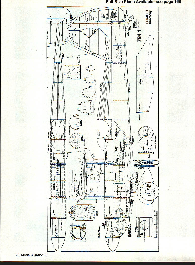
Construction
Good balsa selection is critical for a light model. Note firmness of stock and order plenty of extra balsa to give yourself a good selection.
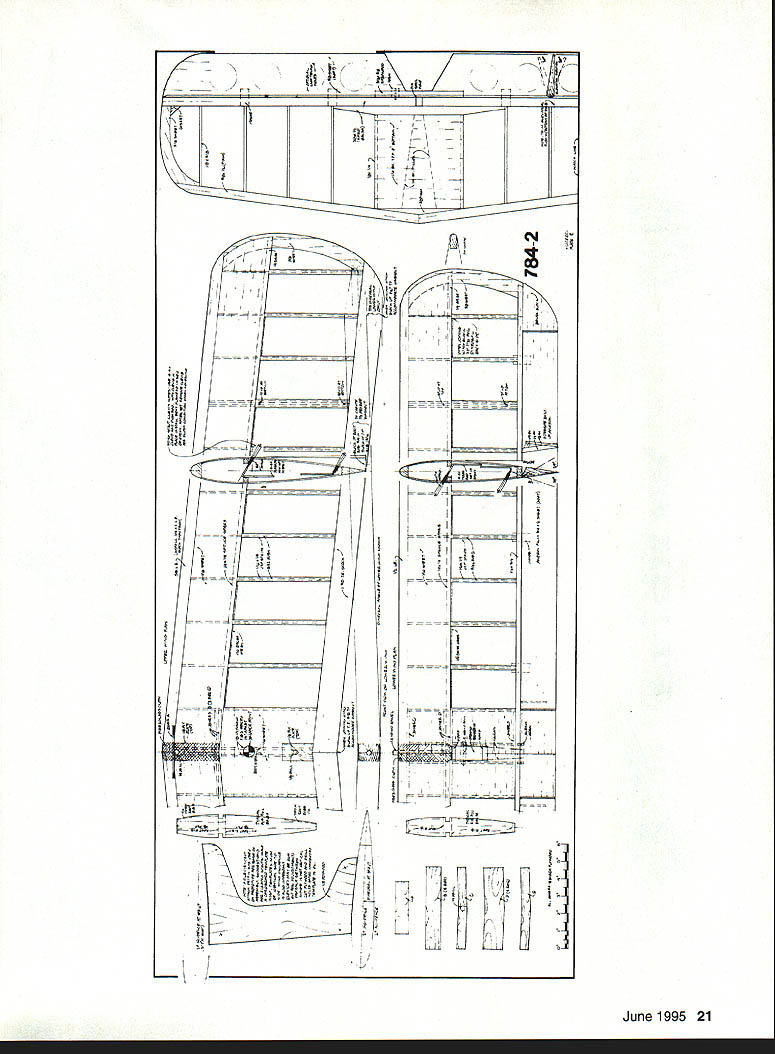
Wing Construction
Detailed completion requires accurate D-tube work on the workbench. Cut spar notches and make ribs true; ends must be accurate for good alignment. Stack ribs, fit scrap spars, and check uniformity. True the leading and trailing edges and use a straightedge when sheeting the wing.
Steps for building the wing panels:
- Begin by pinning down the bottom leading-edge sheet and the bottom spar. Glue the spar to the sheet.
- Slip the ribs onto the spar. Pin the trailing edge in place, propping it up appropriately (note the upper-wing washout), then glue the ribs.
- Install the top spar.
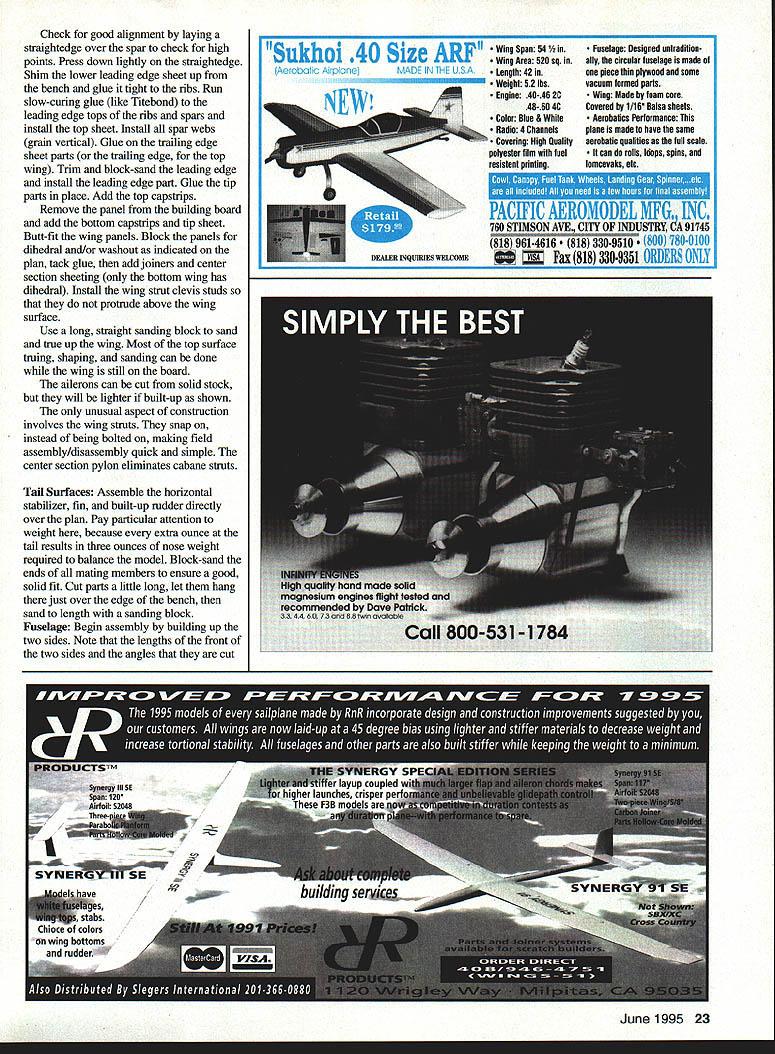
- Check for good alignment by laying a straightedge over the spar to detect high points. Press down lightly and shim as needed.
- Glue the lower leading-edge sheet tight to the ribs. Run slow-curing glue (such as Titebond) to the leading-edge tops of the ribs and spars and install the top sheet.
- Install all spar webs (grain vertical). Glue on the trailing-edge sheet parts (or the trailing edge, for the top wing). Trim and block-sand the leading edge and install the leading-edge part. Glue the tip parts in place and add the top capstrips.
- Remove the panel from the building board and add the bottom capstrips and tip sheet. Butt-fit the wing panels.
- Block the panels for dihedral and/or washout as indicated on the plan, tack-glue, then add joiners and center-section sheeting (on the bottom wing this has dihedral).
- Install the wing-strut clevis studs so they do not protrude above the wing surface.
- Use a long, straight sanding block to sand and true up the wing. Most of the top-surface trimming, shaping, and sanding can be done while the wing is still on the board.
- The ailerons can be cut from solid stock, but they will be lighter if built-up as shown.
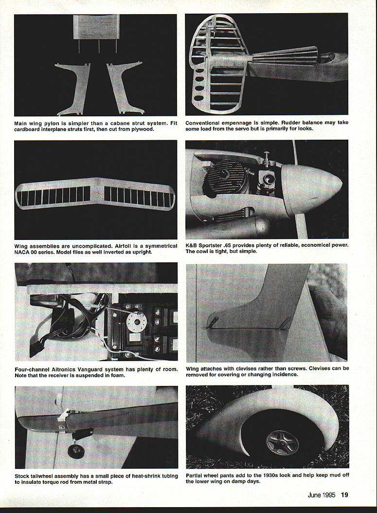
Note: The only unusual aspect of construction involves the wing struts. They snap on instead of being bolted on, making field assembly/disassembly quick and simple. The center-section pylon eliminates cabane struts.
Tail Surfaces
Assemble the horizontal stabilizer, fin, and built-up rudder directly over the plan. Pay particular attention to weight here: every ounce at the tail results in three ounces of nose weight required to balance the model. Block-sand the ends of all mating members to ensure a good, solid fit. Cut parts a little long, let them hang just over the edge of the bench, then sand to length with a sanding block.
Fuselage
Begin assembly by building up the two fuselage sides. Note that the lengths and angles at the front of the two sides determine engine alignment (down and right thrust improve flight characteristics). Cut all formers to shape. Assemble the formers and crosspieces to the fuselage sides over the plan to ensure good alignment. The rudder post must be on the centerline.
- Drill the firewall for the engine mounts and install blind nuts.
- Install all top and bottom fuselage sheeting.
- Drill the landing gear mount to match the gear and add blind nuts. Do not install the landing gear mount until after the wing pylon has been attached to ensure good access for gluing.
- Install the top stringers.
All control surfaces are center-hinged except the ailerons, which are top-hinged for good upper-surface continuity and a close fit (prevents flutter and improves control response). Slot for hinges with a #11 X-Acto blade. Sig Easy Hinges were used and glued with cyanoacrylate (CyA) after check-fitting. Trim hinge corners to promote easier installation.
An inverted engine installation is shown, with an open slot for cooling. The stock K&B .65 muffler fairs well with the fuselage. The only complication with this installation is getting the cowl on and off around the muffler and needle valve (the needle valve must be removed to remove the cowl), but the installation is neat.
The cowl is built from 1/2-inch soft balsa blocks tack-glued to the firewall and built around the installed (but mufflerless) engine with spinner. Tack 1/16-inch balsa spacers to the spinner for clearance, then install the plywood nose ring. Carefully carve and shape the cowl, and thoroughly fuelproof the inside. If you make first flights with the cowl removed, add compensatory weight to ensure proper balance. The cowl is mounted at three points with sheet-metal screws into hardwood blocks.
The prototype was covered with Coverite 21st Century film. Some parts (landing gear, wheel spats, wing pylon, cowl) were painted with 21st Century sprays, which work very well. Film covering is expedited by using the new Coverite computer-controlled iron, which maintains accurate temperature. (Jeff Troy at Coverite can provide an excellent tape on installing 21st Century film.) Cover the bottom panels first and overlap joints or changes in color trim by 1/4 inch.
During final assembly it is important to maintain precise alignment. Begin by fitting the lower wing to the fuselage. A perfect fit can be had by taping the wing, applying lipstick to the tape, trial-fitting the wing to the fuselage, then removing material where the lipstick appears.
Install the 1/4-inch leading-edge dowel. Measure from the wingtips to the tailpost to get the wing centered properly, then drill 3/16 inch and tap 1/4-20 for the wing bolts. Bolt the lower wing in place. Install the horizontal stabilizer using the lower wing as a reference. Install the fin using the horizontal stabilizer to provide reference. Lay the upper wing on the pylon and align it in plan view against the lower wing. Drill 3/16 inch and tap 1/4-20 for the hold-down screws.
Check incidences using distance from the workbench. Use these dimensions when checking incidences:
- With the landing gear removed and the fuselage resting on the lower wing, block up the tailpost 2-5/8 inches.
- The centerline of the leading edge of the lower wing should be 9/32 inch higher than the trailing edge.
- The leading edge of the upper wing (at the root) should be 9/16 inch higher because of the washout.
- The horizontal stabilizer is set at 0° (parallel to the workbench reference).
- The lower wing is set positive (leading edge up) 2°.
- The upper wing pylon holds the upper wing at 3-1/2° positive at the root (1-1/2° more than the bottom wing). The upper wing has 1-1/2° of washout and is parallel to the lower wing (2° positive) at the tip.
Do not cut the plywood interplane struts until the entire model has been assembled. First cut cardboard templates that can be trimmed or added to make them right. Check the struts side-to-side for uniformity. When satisfied, cut the final plywood struts.
The wheel spats are held in alignment with the landing gear bow by cutting out the inner plywood part to fit the bow. Do not use easily deformed wheels, which may bulge and bind on hard landings.
Flying
Taxiing with this taildragger is not tricky. Keep up elevator to maintain tailwheel contact with the ground. When you apply power to take off, the rudder provides positive directional control. Let off elevator when the model begins to accelerate to allow the tail to rise and the model to build speed. Very steep climbs are possible with a fully broken-in engine.
Flicker is surprisingly responsive in all axes. The CG is placed so it is not twitchy, yet Flicker will snap and spin if asked to. Consecutive rolls and inverted slow flight are easy and natural. You can control the model nicely through loops and rolls. Just be cautious on landing: Flicker will descend fairly steeply on final with low idle. Keep a little power until you are over the threshold and ready to touch down. Try to make wheel landings.
Rudder action is strong. Stall turns, etc., are quick and precise. There is more rudder than required for knife-edge, so your first knife-edge flights will tend to climb until you get the feel. Flicker will roll on rudder and will execute 360° turns without ailerons if you are curious.
Biplanes have more drag than equivalent monoplanes, so expect shorter, steeper approaches. Flicker may be larger than the model you have been flying; this requires more room to make your landings. If you are used to flying small monoplanes, pick a landing spot about one third down the runway for your first biplane landings.
Transcribed from original scans by AI. Minor OCR errors may remain.

