

Float & Hull Design
Ed Westwood
In my efforts to design float models and seaplane hulls, I have developed several formulas based on experience. I have also drawn upon the old Langley water tank report data to complete my bag of tricks. When my bag failed me, I would just go for cut‑and‑try, and after two or three or more design variations I'd get it to work.
I'd like to pass on what I've learned and hopefully save you readers the time I've spent. One thing is certain in this business: no matter how well a set of design formulas seem to work, there will always be that slightly different situation that requires testing a couple of hull variations to get satisfactory performance. In these cases, experience and perseverance will usually win the day.
Right up front, we should discuss what a successful water‑borne hull, either single or twin, should do. It should:
- Hold up its share of the model's weight with enough spare buoyancy to allow it to plane easily when driven forward at speed.
- Be watertight, durable, and offer low drag when flying.
- Deflect spray away from the hull so it will not interfere with the aircraft.
- Rise smoothly from displacement to planing with just a little aft stick.
- Not porpoise during takeoff or landing runout, nor tend to snake when planing or skip when landing.
- Have step placement and afterbody angle such that it can be pitched to the aircraft's stalling angle of attack for takeoff and landing.
- Be a level of construction complexity commensurate with the model above it.
Our goal is to meet all these criteria with your first design. Let us discuss the parameters that influence float and hull performance, and the formulas that proportion them.
Twin‑Float Length
Floats are often added to models designed primarily for land use. Generic cross‑section sizing formulas for twin floats use lengths around 75% to 80% of the fuselage, measured from prop to rudder TE (trailing edge). A more exact determination involves doubling the distance from a point one‑third of a prop diameter ahead of the propeller plane to a point directly below the 40% MAC (Mean Aerodynamic Chord) or root chord. A few installations may require slightly more float ahead of the prop. Without it, a touch of up elevator during power‑up usually solves any plowing tendency.
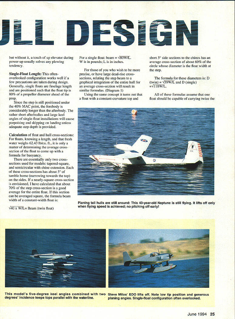
Single‑Float Length
This often‑overlooked configuration works well if a few precautions are taken. Generally, single floats are full fuselage length and are positioned so the float tip is about 0.8 propeller diameters ahead of the prop. Since the step is still positioned under the 40% MAC point, the forebody is considerably longer than the afterbody. The rather short afterbodies and large keel angles of single‑float installations can cause porpoising and skipping on landing unless adequate step depth is provided.
Calculation of Float and Hull Cross‑Sections
Fresh water weighs 62.43 lb/ft³. Given float length, average cross‑section determines buoyancy.
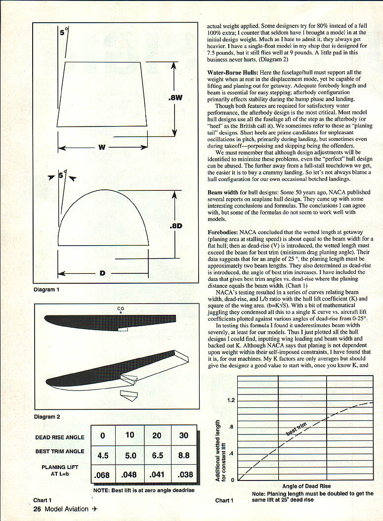
There are essentially two cross‑sections used for models:
- Tapered‑square
- Semicircular with chine extension
Each of these cross‑sections typically has about 5° of tumble‑home (narrowing toward the top) on the sides. If a nearly‑square cross‑section is envisioned, about 70% of the step cross‑section is a good average for the entire float. If this section can be averaged square, the formula for beam width of a constant‑width float is:
- Beam (twin float) = √(40 × W / L)
- Beam (single float) = √(80 × W / L)
where W is weight in pounds and L is length in inches.
If the float has a constant‑curvature top and short 5° side sections to the chines, the average cross‑section is about 60% of the circle whose diameter equals the float width at the step. The formula for these diameters is:
- D (twin) = √(59 × W / L)
- D (single) = √(118 × W / L)
All of these formulas assume one float should be capable of carrying twice the actual weight applied (i.e., 100% reserve). Some designers aim for only a 80% reserve, but models often end up heavier than initial estimates. A little margin is wise.
Water‑Borne Hulls
Here the fuselage/hull must support all weight when at rest (displacement mode) yet be capable of lifting and planing out for getaway. Adequate forebody length and beam are essential for easy stepping; afterbody configuration primarily affects stability during the hump phase and landing.
Although both forebody and afterbody features are required for satisfactory water performance, the afterbody design is the most critical. Most model hulls use all the fuselage aft of the step as the afterbody (the British call this the "heel"). These "planing tail" designs with short heels are prime candidates for unpleasant pitch oscillations during landing (porpoising and skipping) and sometimes during takeoff.
Design adjustments can minimize these problems, but even a "perfect" hull can be mishandled: a touchdown far from a full‑stall attitude will often produce a poor landing. Don't always blame hull configuration for occasional botched landings.
Beam Width for Hull Designs
NACA published reports on seaplane hull design many years ago and derived relationships among beam width, dead‑rise, and planing length. Their conclusions are useful, but some formulas do not scale well to models.
Forebodies
NACA concluded that for a flat hull the wetted length at getaway (planing area at stalling speed) is about equal to the beam width. As dead‑rise (V) is introduced, the wetted length must exceed the beam for best trim (minimum drag planing angle). Their data suggest that for 25° dead‑rise, the planing length must be approximately two beam lengths. They also found that as dead‑rise increases, the angle of best trim increases. (See chart references in the original NACA data.)
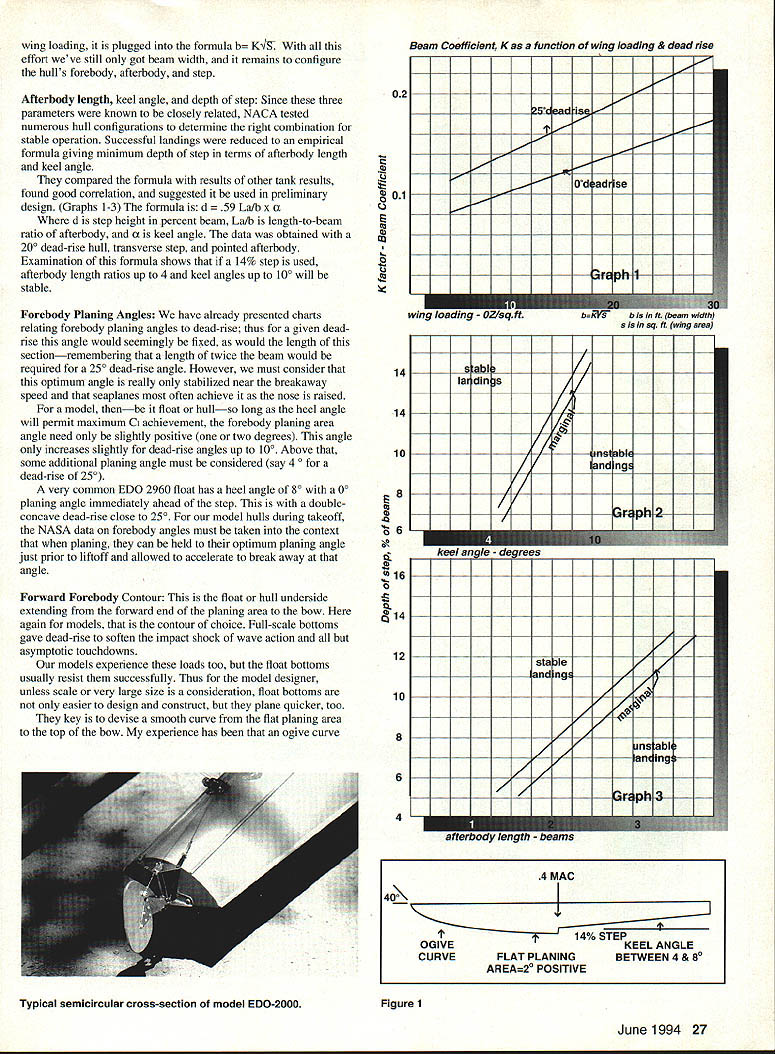
NACA's testing produced curves relating beam width, dead‑rise, and L/b ratio with the hull lift coefficient (K) and wing area (their relation: b = K√S). In testing with models I found NACA's formula tends to underestimate beam width. I plotted many hull designs, input wing loading and beam width, and backed out K. My K factors are averages but should give a designer a good starting value; once you know K you can use b = K√S to estimate beam width for your model.
Afterbody Length, Keel Angle, and Depth of Step
Because these three parameters are closely related, NACA tested many configurations to determine the right combination for stable operation. Successful landings were reduced to an empirical formula giving minimum step depth in terms of afterbody length and keel angle. The formula is:
- d = 0.59 × (La / b) × α
where:
- d is step height as percent of beam,
- La / b is the length‑to‑beam ratio of the afterbody,
- α is keel angle.
The data were obtained with a 20° dead‑rise hull, transverse step, and pointed afterbody. If a 14% step is used, afterbody length ratios up to 4 and keel angles up to 10° will be stable.
Forebody Planing Angles
Charts relating forebody planing angles to dead‑rise show that for a given dead‑rise the optimum planing angle is relatively fixed, and forebody planing length follows accordingly (remember: planing length ≈ twice beam for 25° dead‑rise). However, this optimum angle is only stabilized near breakaway speed; seaplanes most often achieve it as the nose is raised.
For a model (float or hull), as long as the keel angle permits achieving maximum Cl, the forebody planing area only needs a slightly positive angle (1°–2°) immediately ahead of the step. This angle increases only slightly for dead‑rise up to 10°. Above that, additional planing angle is required (for example, ≈4° for 25° dead‑rise).
A common EDO 2960 float has a heel angle of 8° with a 0° planing angle immediately ahead of the step; this with a double‑concave dead‑rise near 25°. For model hulls during takeoff, hold the forebody near its optimum planing angle just prior to liftoff and accelerate to breakaway at that angle.
Forward Forebody Contour
This is the underside extending from the forward end of the planing area to the bow. For models, a smooth curved contour is preferred: float bottoms (flat planing area with a smooth ogive curve to the bow) plane quicker and are easier to design and build than complex concave shapes. Full‑scale hulls use dead‑rise to soften wave impacts; models experience similar loads, but float bottoms usually resist them successfully.
The key is a smooth curve from the flat planing area to the bow. An ogive curve works well provided the bow angle does not exceed about 40°. Keep the planing area flat. If a constant dead‑rise is used, maintain the same angle throughout to simplify design and construction. Scale models may require transverse concave curvature and varying dead‑rise—often a task for glass molding.
Float Tips
On single‑float installations, round the upper surface at the bow to eliminate audible propeller cavitation in high‑G maneuvers. On twin‑float installations, slight rounding improves appearance but usually gives no discernible performance change; any separation tends to pass to either side of the prop.
Afterbody Bottom Contour and Shape
For models, a flat afterbody bottom is again the contour of choice. Full‑scale afterbodies often use limited dead‑rise, even though forebodies may carry double‑concave contours on the planing surfaces. If an afterbody terminates short of the tail, a pointed stern has no adverse water‑handling qualities and offers less drag.
Step Configuration
All float steps are transverse to start with. Some full‑scale designs use a pointed step to lessen impact loads, reduce flying drag, and improve handling. I found that adding a pointed step to a porpoising single float calmed it appreciably; the apex was only one beam width long and matched the planing angle. Had the step been deep enough initially, pointing would not have been required.
For model hulls, unless scale appearance dictates otherwise, transverse steps usually perform satisfactorily. If you have porpoising or skipping issues, adding a pointed apex to the existing step can damp porpoising and reduce skipping—especially if the existing step is below the CG and not well behind it.
Increasing step height by extending the planing surface rearward will only work if the resulting mean step position does not extend beyond the 40% MAC.
Tip Floats
Successful tip‑float design involves three factors:
- Displacement buoyancy
- Planing lift
- Buoyant position when the model is planing
Displacement buoyancy: One common error is undersizing tip floats. They must not only hold up the wing during calm displacement operation but also during turns in wind. Tip‑float size is the limiting factor for successful operation in wind. General rules:
- For a 40‑inch span airplane, tip floats should displace about 12%–16% of the aircraft weight. For larger models, the percentage can be smaller.
- For no‑wind operation, a float that just raises the wing when pushed under is sufficient—try a contoured foam block as a test.
- For windy operation, a starting geometry is: length ≈ two‑thirds of the wing chord, width ≈ one‑third of the chord, and depth ≈ one‑third of the chord.
Planing surfaces: The forebody bottom can be flat or V‑shaped. At the rear, an angled flat surface (about 10° to the model's waterline) should present itself to the water. Its width at the stern should be at least the float's maximum width.
Height: Many place tip floats too high. High floats allow crosswinds to raise the upwind wing where the opposite float may be ineffective. I check that the top of the tip float planing surface is level with the top of the hull's step. This ensures that during displacement both tip floats are immersed, and only at liftoff do they stop stabilizing.
Construction note: Tip floats tend to be brittle. Rather than heavy, rigid struts that can still break off, I use weak struts that allow the float to break off in a repairable location.
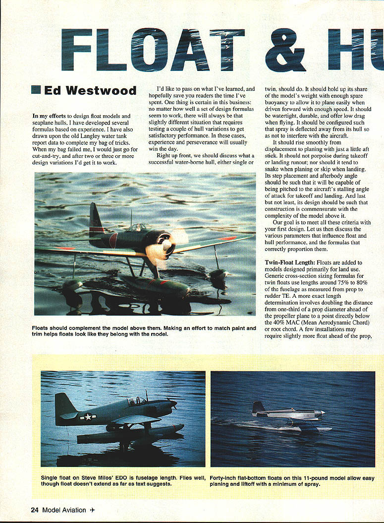
Summary guidance on appearance: Floats ought to look like they belong with the model—clunky with clunky, light with rounder—matched contours and colors. Use your pencil and eye to coordinate water equipment with the rest of the model.
Summary
- Determine correct float length first. Knowing the completed model weight, calculate width using the provided formulas.
- Forebody planing angle should be only slightly positive (1°–2°) immediately ahead of the step; planing area should be flat with an ogive curve to the bow.
- Step height: about 14% of the beam is a good starting point.
- Keel angles should permit achieving the wing's maximum Cl (normally 4°–8°).
- For hulls, with wing area and estimated stall speed you can determine step height and afterbody keel angle for stable takeoffs and landings.
- Afterbody length influences stability; for flat bottoms planing length ≈ one beam, and for 25° dead‑rise planing length ≈ two beam widths.
- Planing angle is controlled by the afterbody keel angle; start with a couple of degrees positive rather than parallel to the waterline.
- Ensure forebody length and beam are sufficient to support and raise the nose for the initial hump phase. Failure to provide adequate forebody length and beam will cause plowing and may prevent humping entirely.
Transcribed from original scans by AI. Minor OCR errors may remain.

